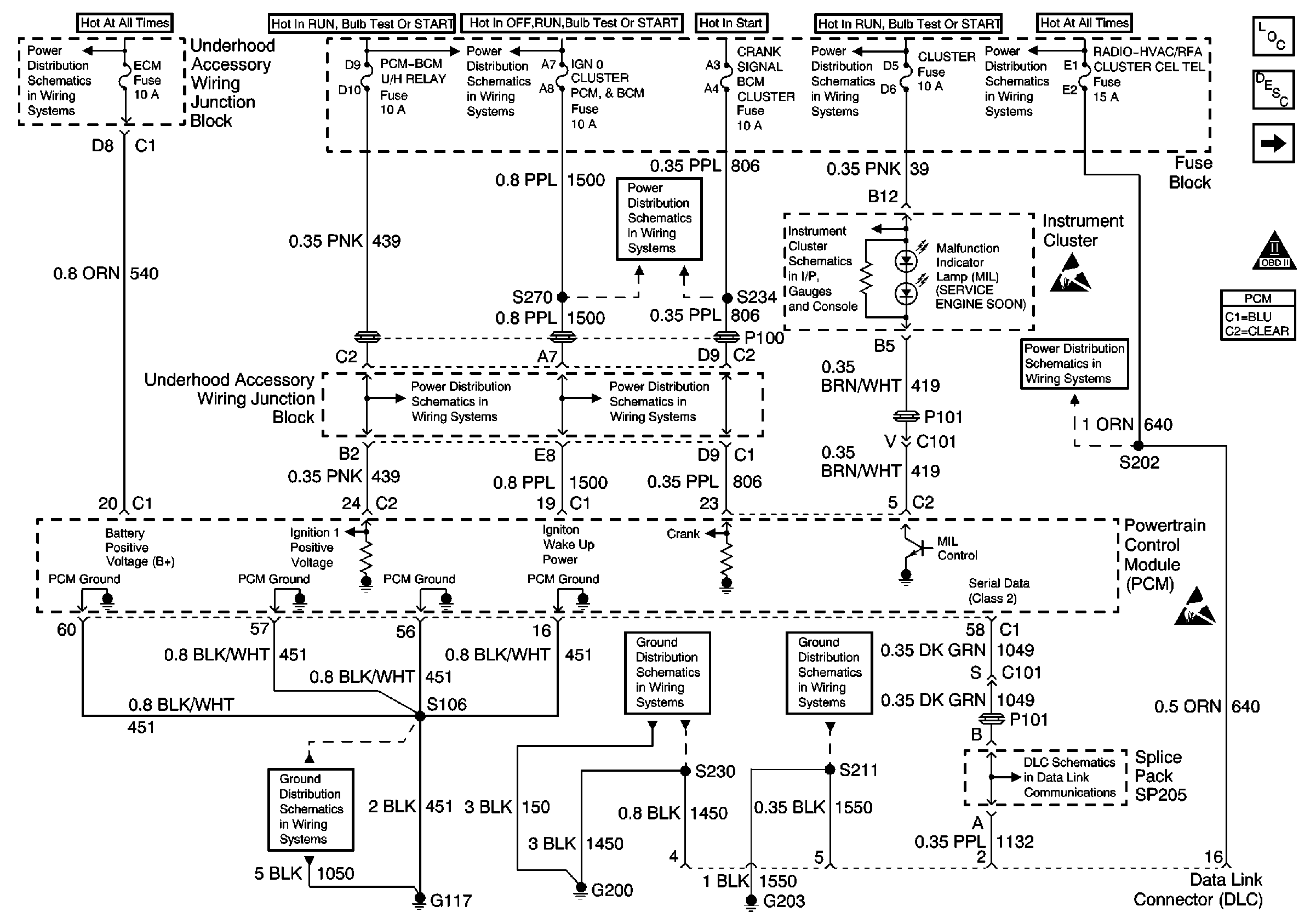
| Figure 1: |
PCM Power and Grounds
|
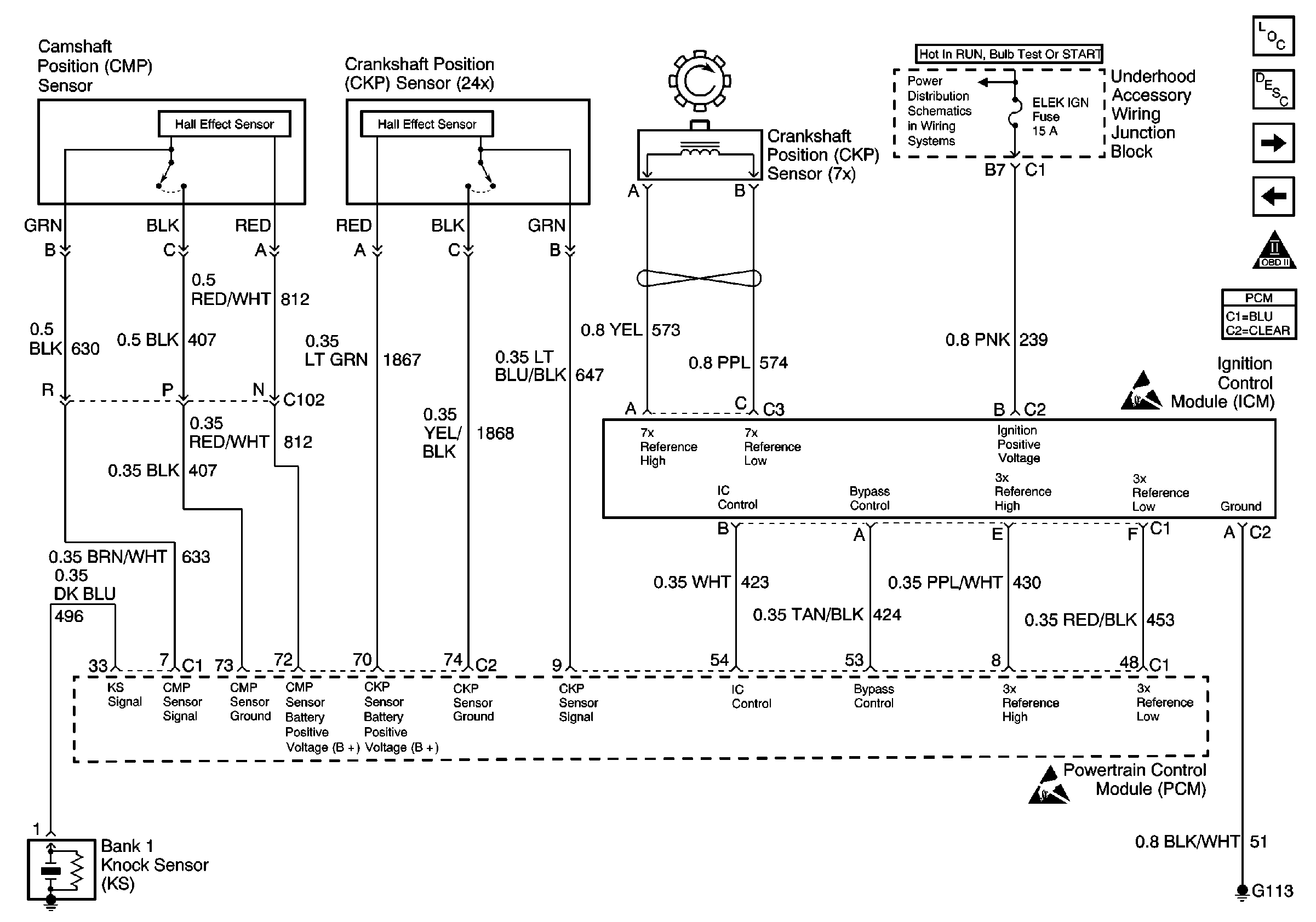
| Figure 2: |
Camshaft and Crankshaft Position Sensor
|
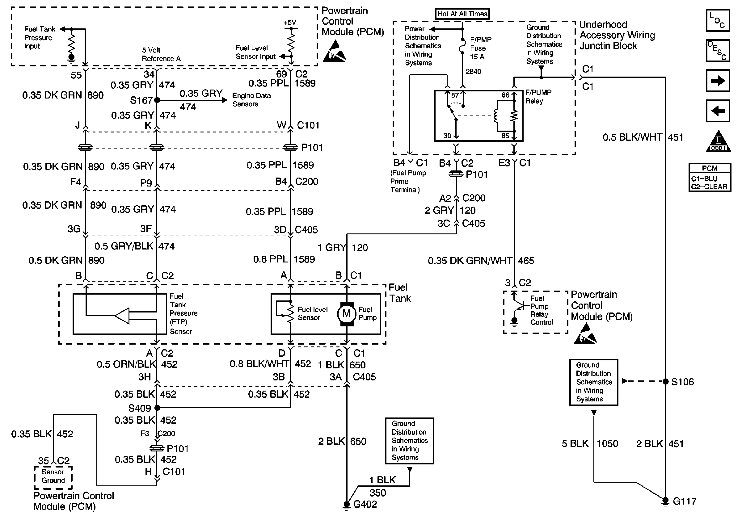
| Figure 3: |
Fuel Tank Inputs
|
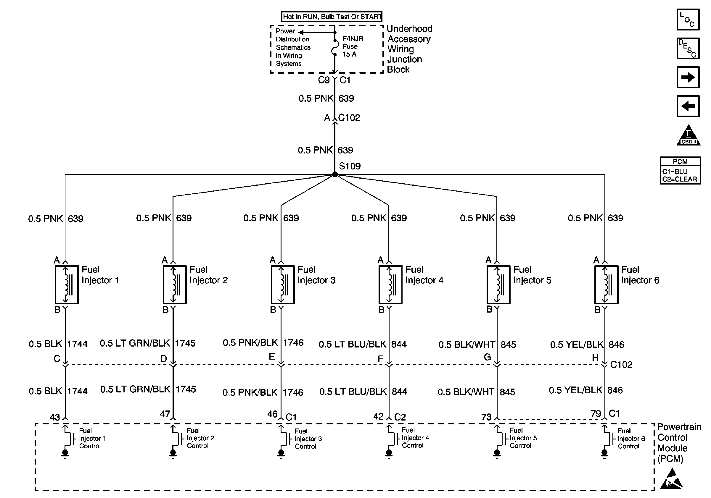
| Figure 4: |
Fuel Injectors Input
|
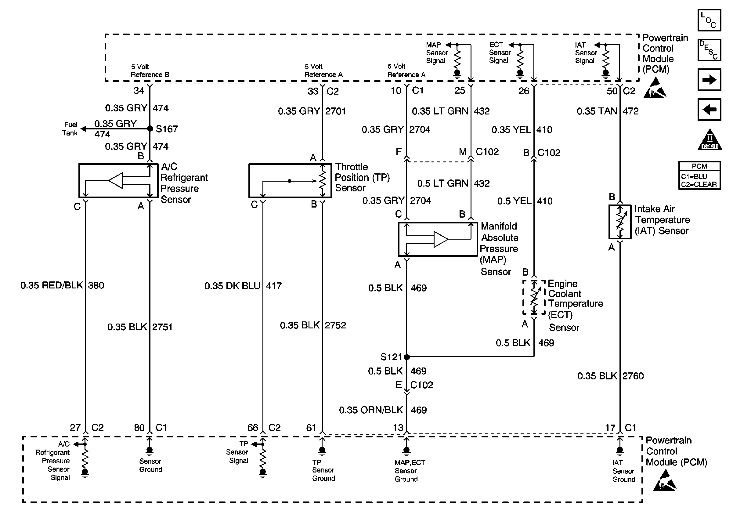
| Figure 5: |
A/C, Throttle Position, Manifold Absolute Pressure, Engine Coolant
Temperature and Intake Air Temperature Sensors
|
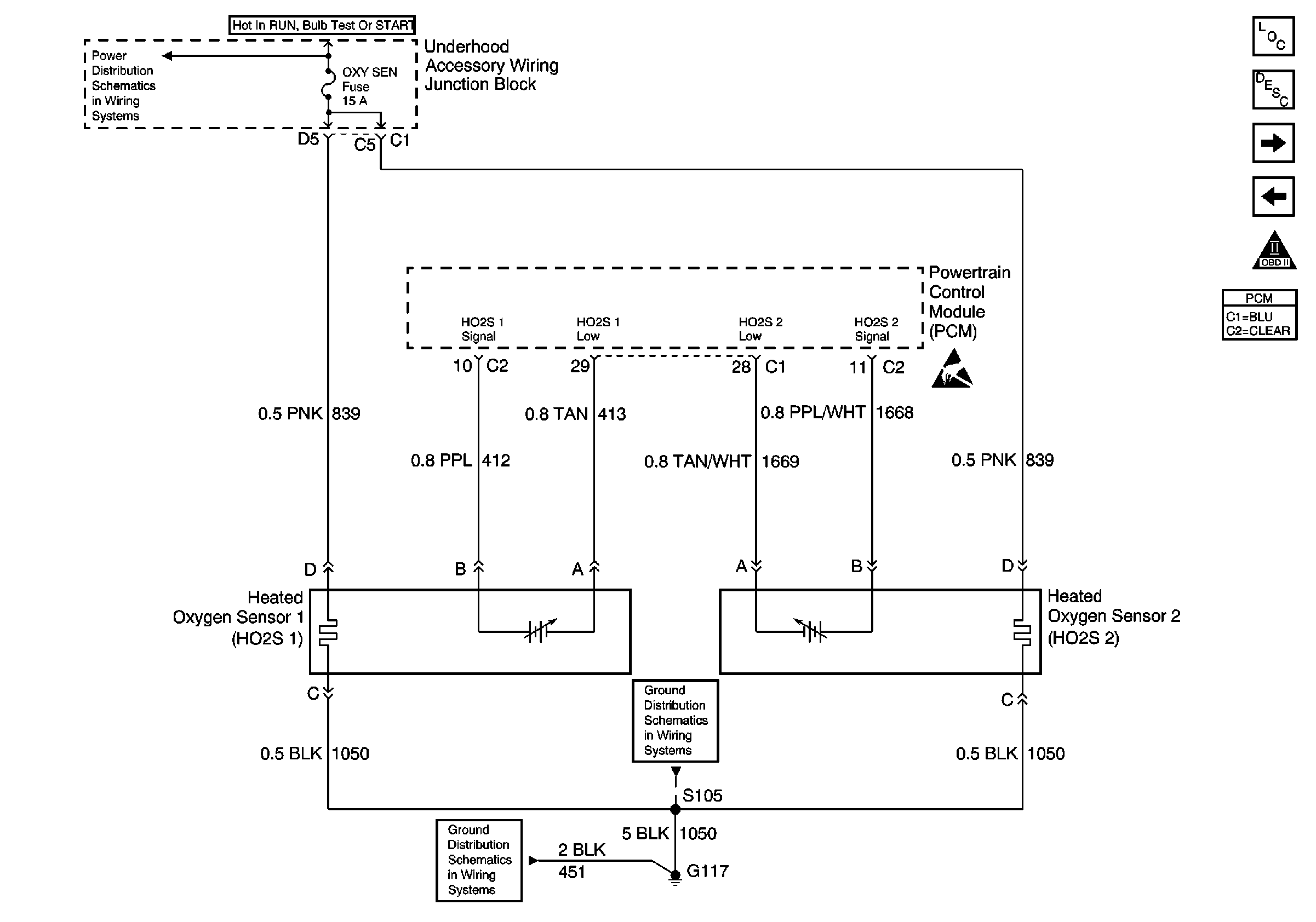
| Figure 6: |
Heated Oxygen Sensors
|
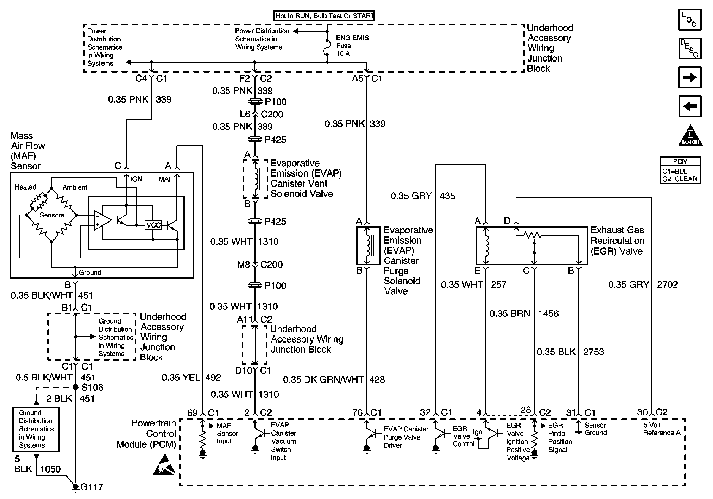
| Figure 7: |
Mass Air Flow, EGR Valve and EVAP Canister Vent and Purge Solenoids
|
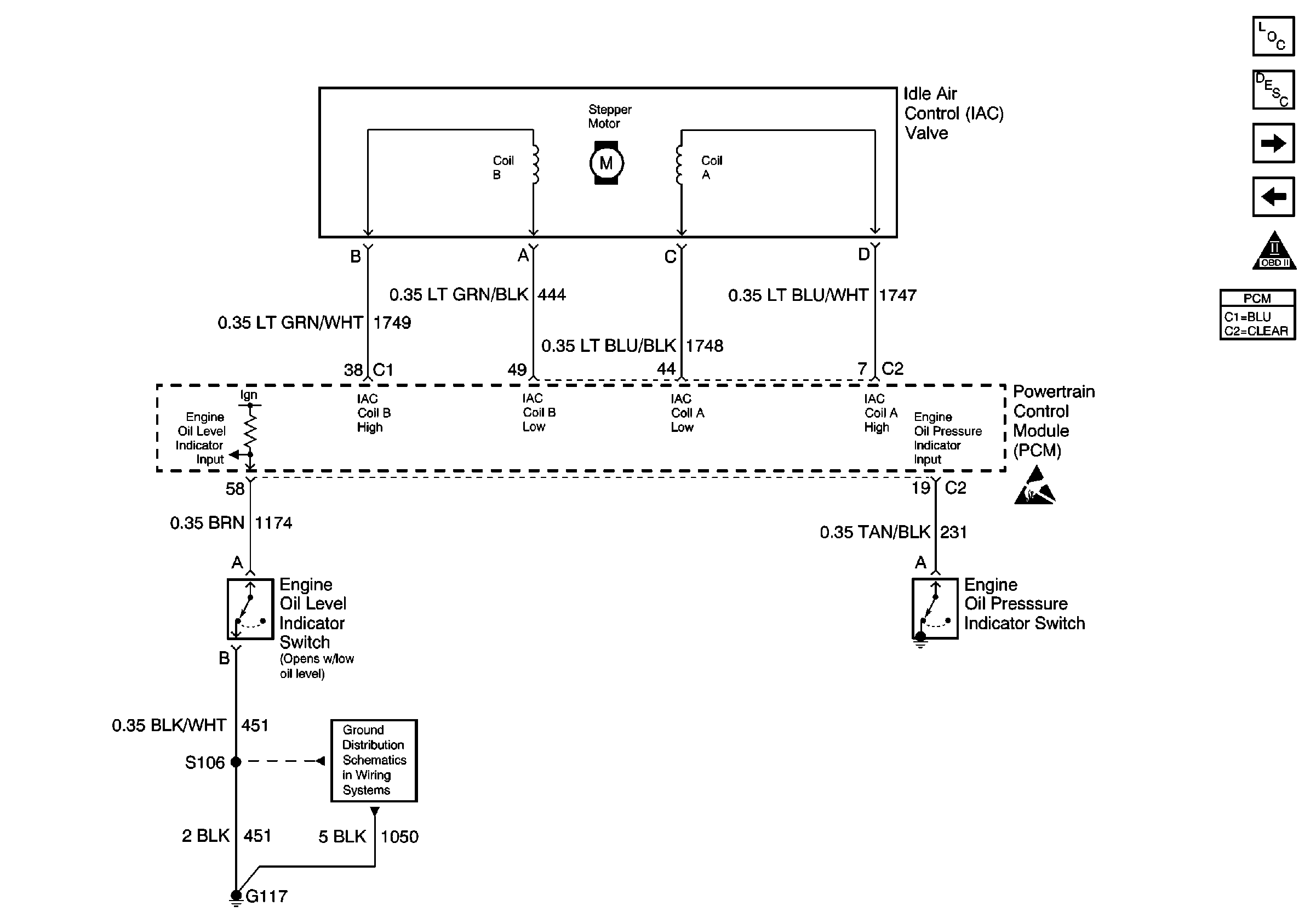
| Figure 8: |
Idle Air Control Valve Inputs
|
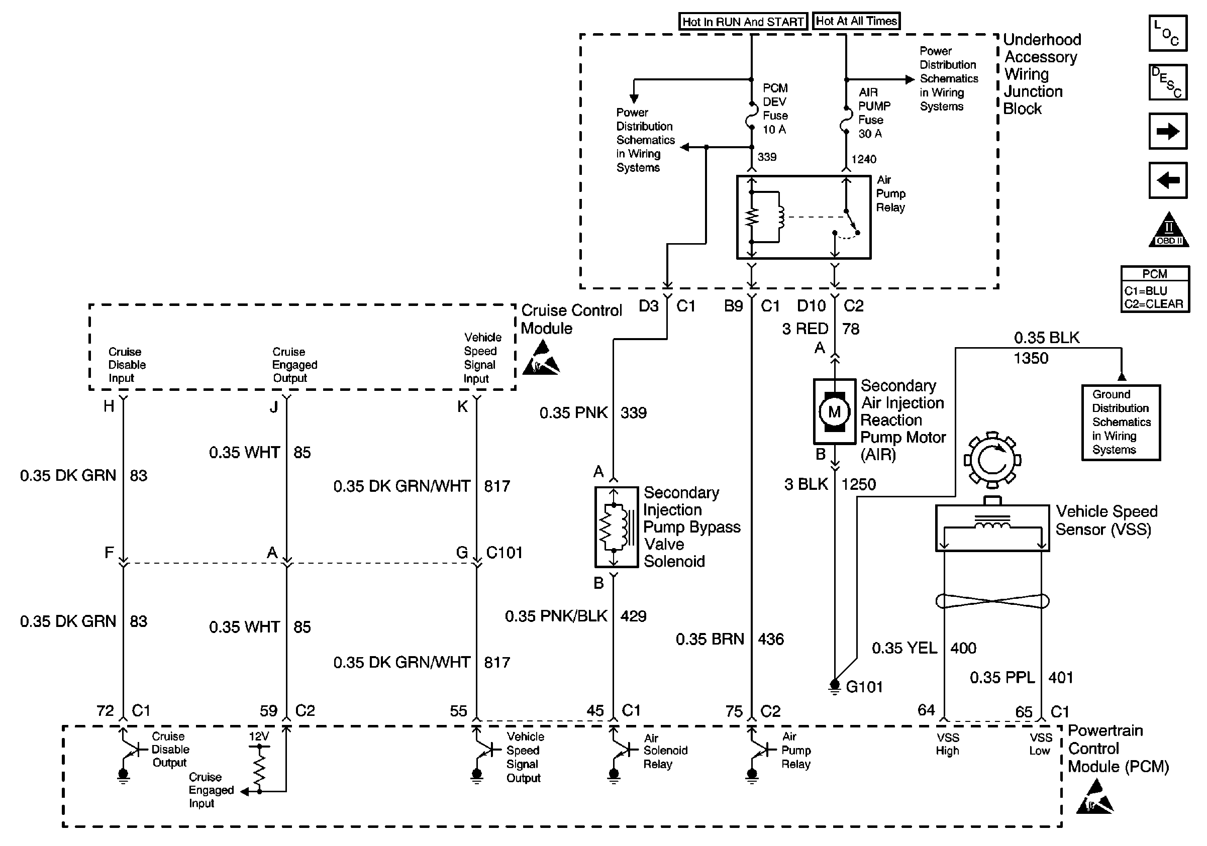
| Figure 9: |
Cruise Control Module Input/Output and AIR System
|
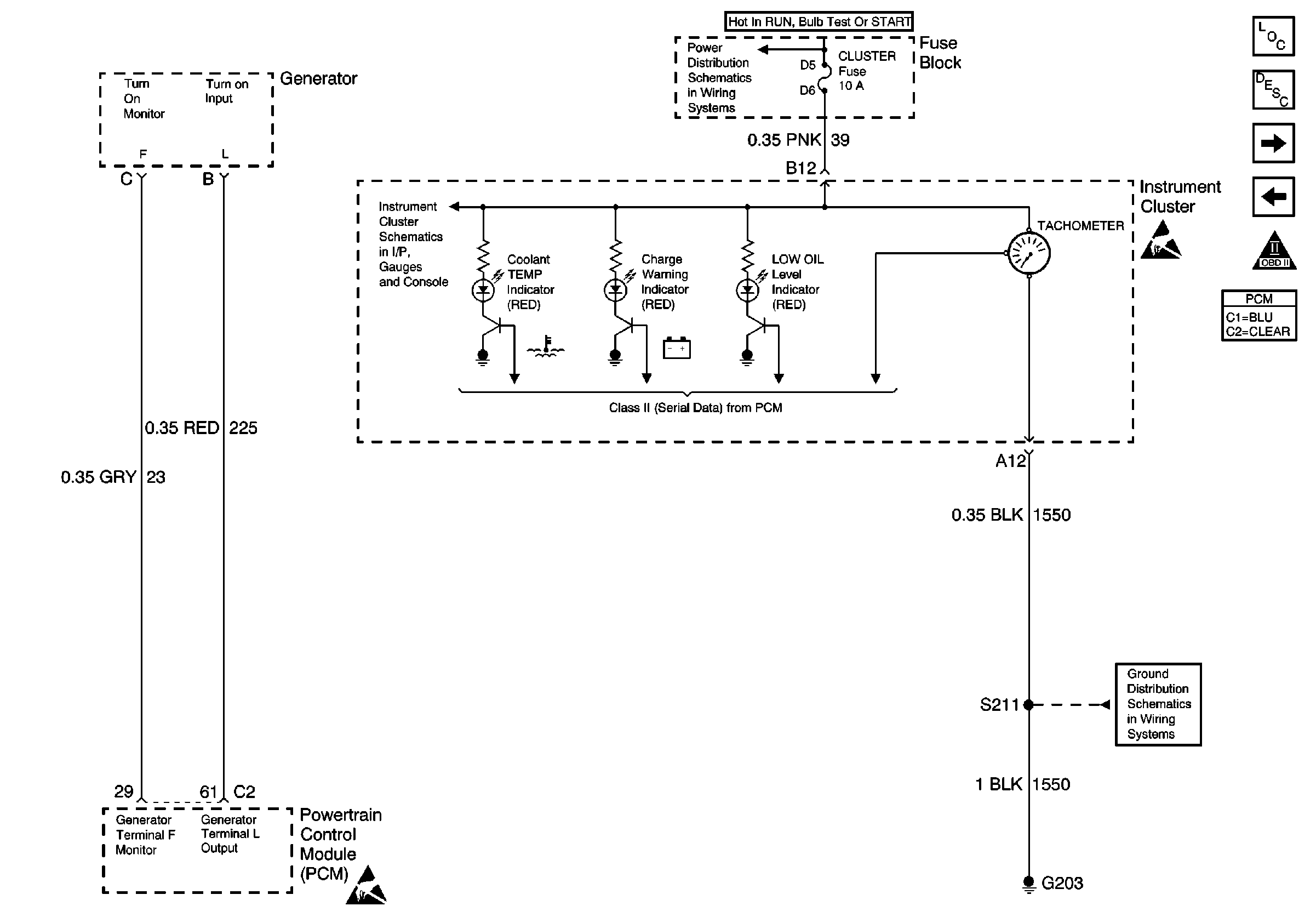
| Figure 10: |
IPC Class 2 Serial Data Input from PCM and Generator Input/Output
|
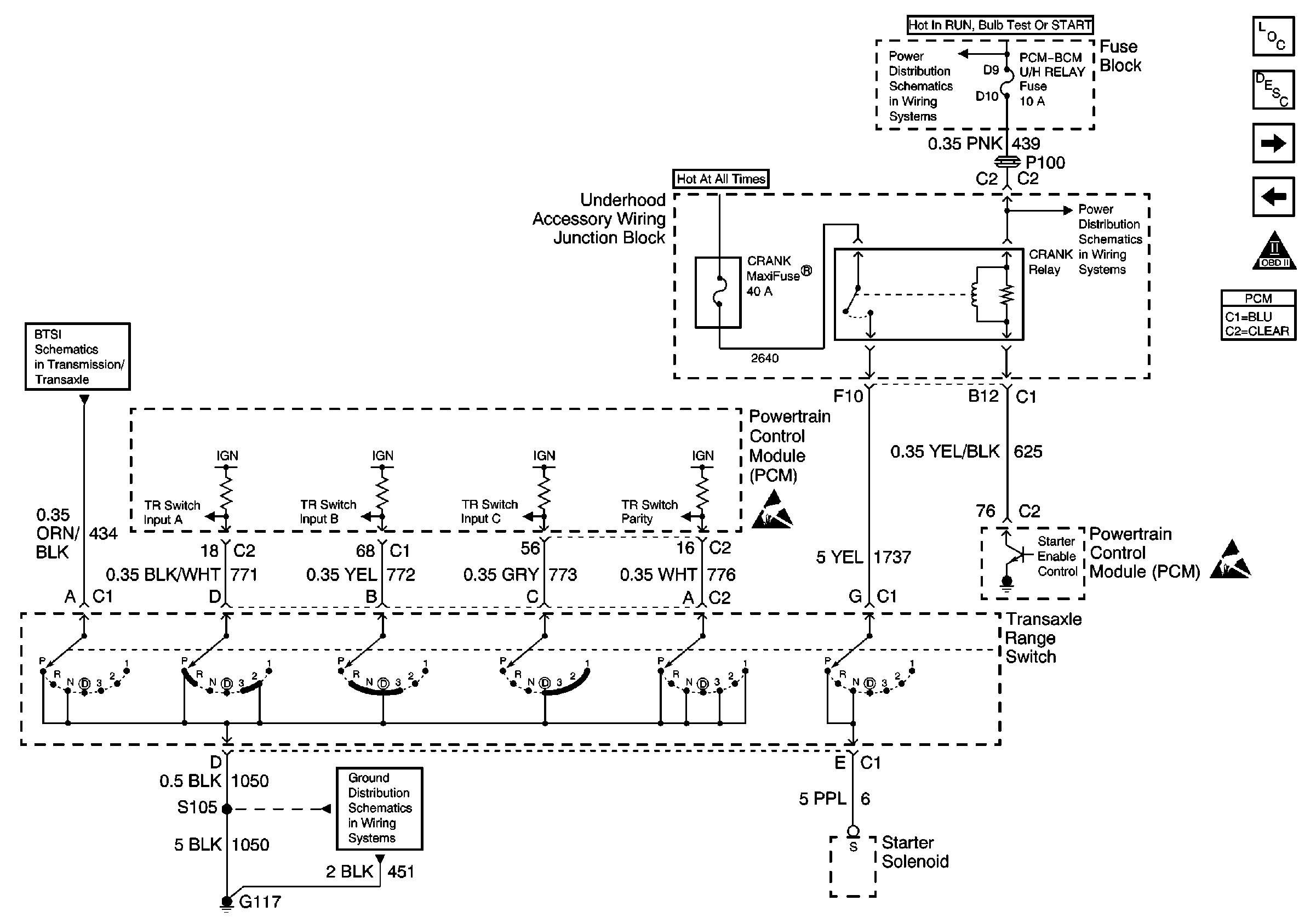
| Figure 11: |
Transaxle Range Switch Inputs
|
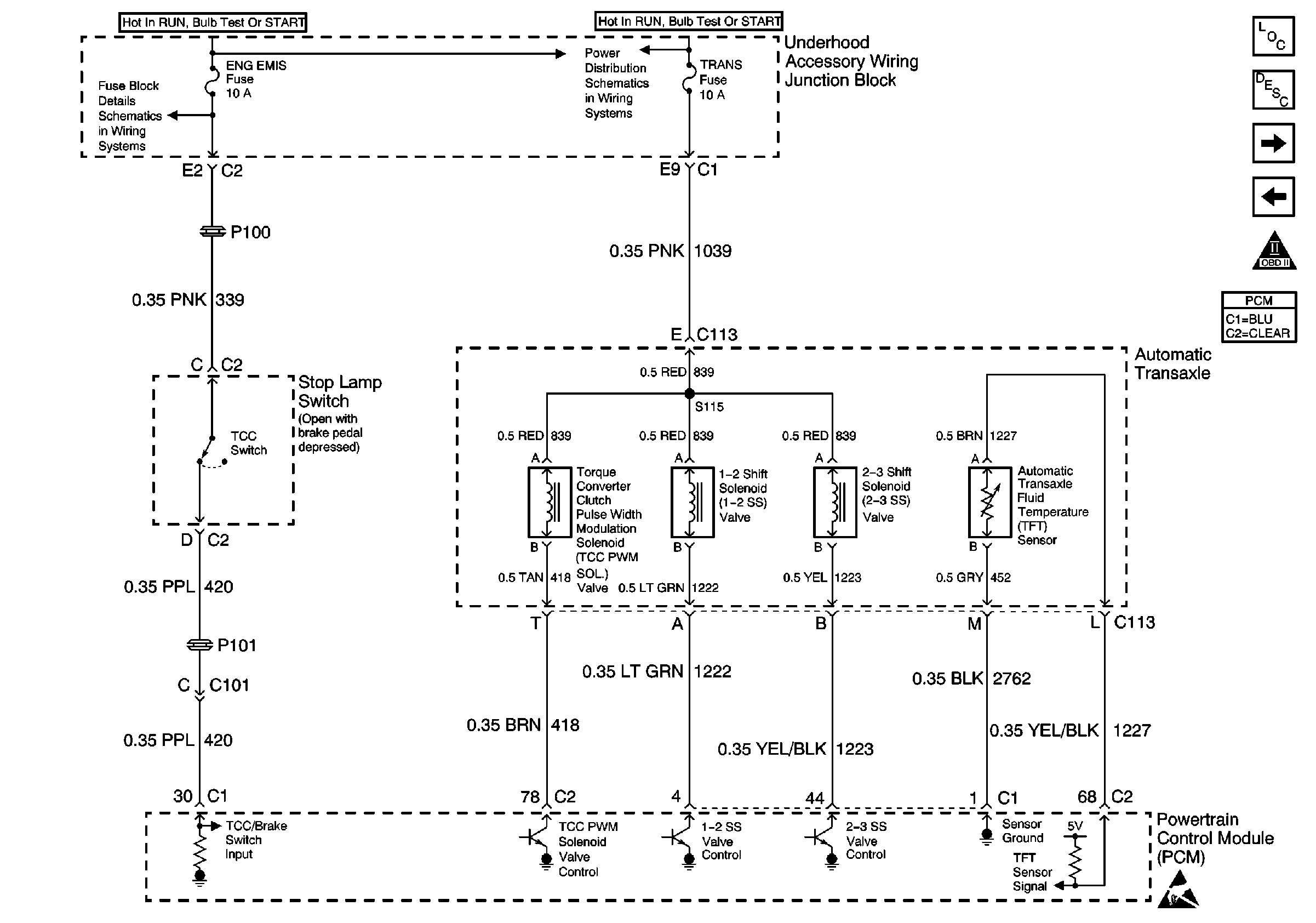
| Figure 12: |
Automatic Transaxle Inputs
|
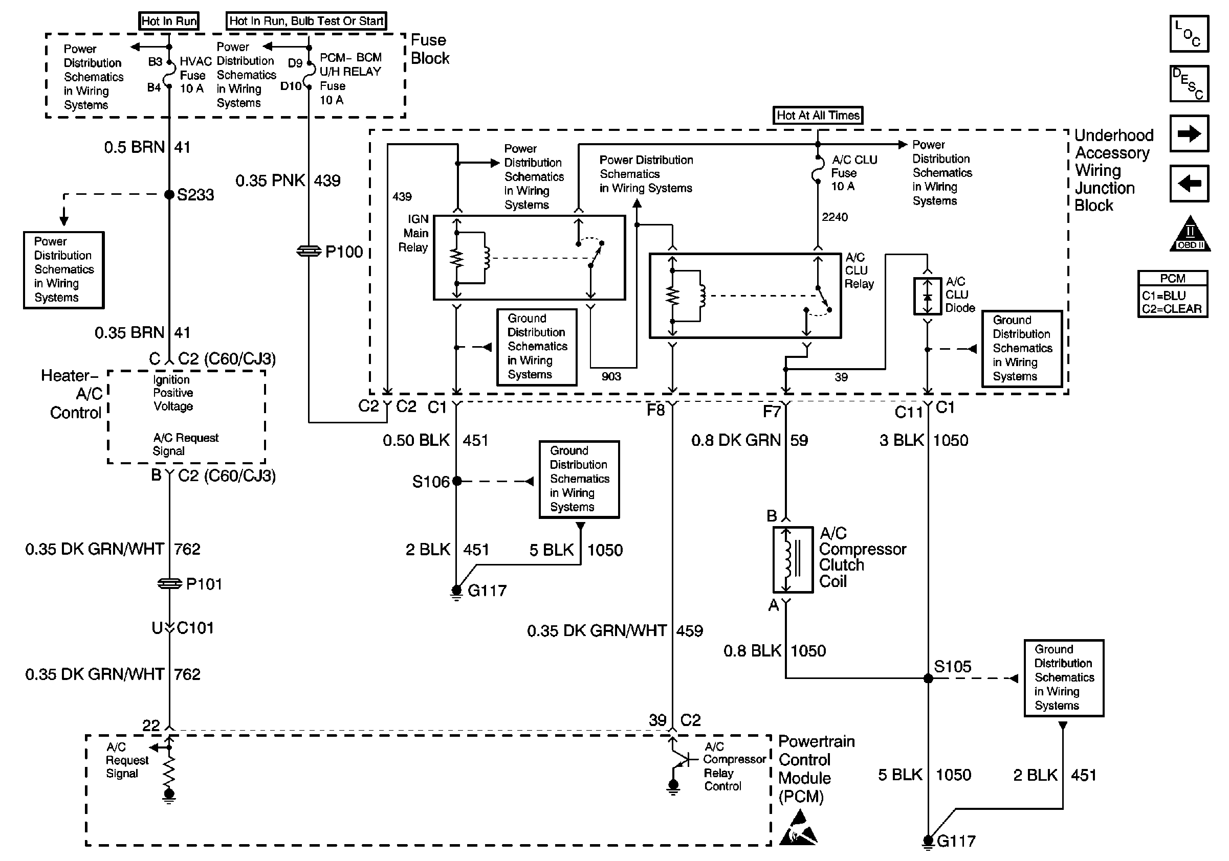
| Figure 13: |
Heater A/C Control Output and A/C Compressor Clutch Coil
|
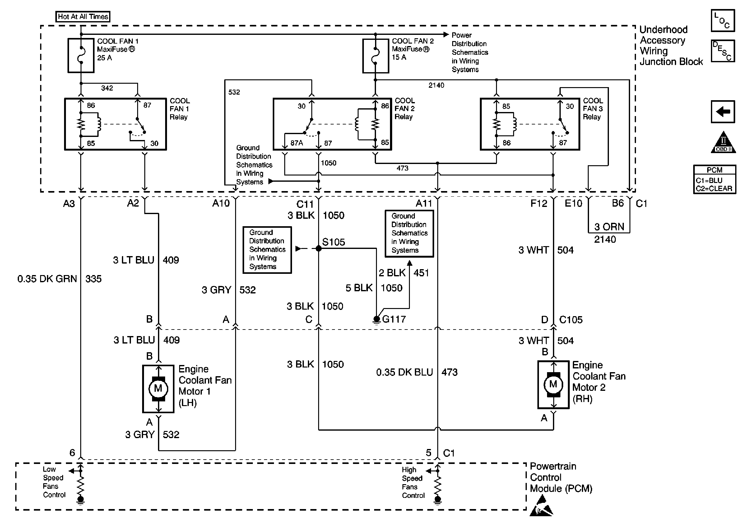
| Figure 14: |
Cooling Fans Output
|


