Caution: Do not operate the detector in a combustible atmosphere since its sensor
operates at high temperature. Personal injury or damage to the equipment may
result.
Important: Vehicles equipped with an early warning system for low refrigerant may
set low refrigerant codes.
Perform a refrigerant leak test on the system whenever a leak is suspected.
Suspect leakage when a system indication of a low charge occurs or after
any service operation which disturbs the following parts:
Halogen Leak Detector
Tools Required
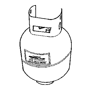
| • | J 39500-50
23 Kg (50 lb) Refillable Recovery Tank |
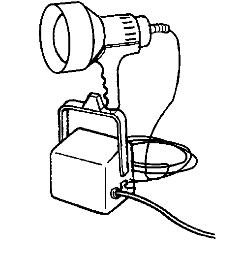
TheJ 39400
Halogen
Leak Detector is the most useful tool in locating refrigerant leaks. TheJ 39400
is a small
unit which operates on 12 V DC and provides an audible
signal which increases in frequency as R-12 or R-134a is detected.
There are three settings:
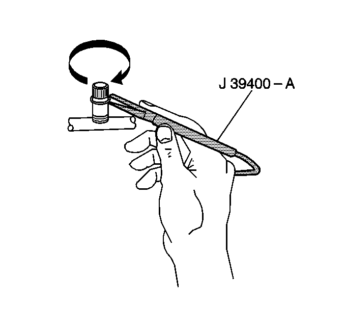
Use the gross leak setting for isolating very large leaks already found
in one of the other two settings.
Ensure that theJ 39400
instrument is properly calibrated according the instrument's instructions.
Ensure that the detector is set properly for the type of refrigerant
system being tested.
Prior to beginning the test, ensure that the refrigerant system is sufficiently
charged for leak testing by measuring the static pressure with a gage set.
Readings in the range 413-689 kPa (60-100 psi)
are acceptable to conduct a leak test.
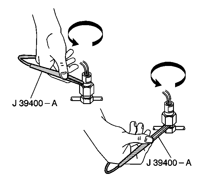
The most common leaks are found at the refrigerant fittings or connections.
Leaks can be caused by the following items:
| • | Lack of lubricant on the O-rings |
| • | Dirt/debris across the O-ring |
A small piece of lint from cotton gloves or shop cloths can create a
leak path across an O-ring.
The successful use of theJ 39400
and any other electronic leak detector depends on the scan
rate. It also depends on carefully following the manufacturer's
instructions regarding the following items:
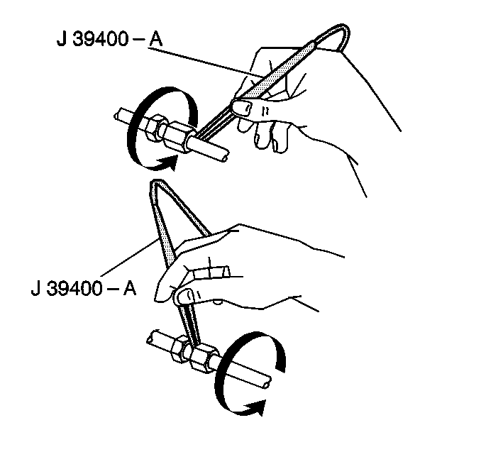
Each joint must be completely circled moving at 1-2 inches
per second with the tip of the probe as close to the surface as possible.
It must be no more than 1/4 inch away and without blocking
air intake. A leak is indicated when the audible tone goes from
a steady 1-2 clicks per second to a solid alarm. Adjust
the balance knob frequently in order to maintain the 1-2
clicks per second rate.
Important: Halogen leak detectors are sensitive to the following items:
| • | Windshield washing solutions |
| • | Low and high side sensors |
| • | Transducers and switches |
| • | Evaporator inlet and outlet |
| • | Accumulator dryer inlet and outlet |
| • | Condenser inlet and outlet |
| • | All brazed and welded areas |
| • | Areas showing signs of damage |
Important: Always follow the refrigerant system around in a continuous path so
that no areas of potential leaks are missed. Test all of the above areas to
ensure that the entire system is leak free, even when a leak was
already found.
Fluorescent Leak Detector
Tools Required
R-134a refrigerant is uniquely different from R-12 refrigerant used
in the past and may require additional methods to detect leaks. The R-134a
molecule is smaller than the R-12 molecule and can leak through
smaller openings. Also, R-134a does not contain chlorine which
the electronic leak detectors found easy to identify. The tracer
dye method is meant to be used in conjunction with the electronic
leak detector and will pinpoint smaller leaks undetected by
using the electronic leak detector. R-134a tracer dye requires
time. Depending upon the rate of leak, it may take up to 7 days
for the leak to become visible.
Important:
| • | The J 41447
has
been developed to be used only with R-134a equipped vehicles or vehicles
that have been retrofitted from R-12 to R-134a. |
| • | Only J 41447
R-134a
Tracer Dye is recommended for use in the R-134a system. Use of any other
products may affect system reliability and cause premature compressor
failure. |
| • | Use only a 1/4 ounce charge of tracer dye. Larger amounts may
compromise the reliability of the A/C system. |
| • | After adding tracer dye, clean service valves and surfaces of
residual dye with GM Engine Degreaser GM P/N 1050436 or the equivalent,
to prevent false diagnosis. |
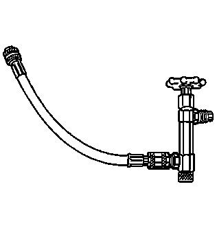
Dye Injection
| • | Charged systems can be injected with tracer dye by using J 41436-1
along with the instructions
provided. |
| • | Discharged systems can have the tracer dye added to a replaced
component, or can be added using the ACR4 unit. |
Liquid Leak Detectors and Pressure Testing
Liquid/bubbles leak detectors have very limited usefulness. This is
due to the restricted visibility in today's refrigerant systems and liquid/bubbles
leak detectors' lack of sensitivity.
Evaporator Core
One of the most difficult leaks to find is in the evaporator core. Follow
the instructions below in order to lead test the core:
- Turn the blower fan on high for 15 or more seconds.
- Shut the blower fan off.
- Wait 10 minutes.
- Remove the blower fan power module or resistor block if accessible.
- If the blower fan power module is not accessible, inspect the
condenser drain tube for moisture.
- If the condenser drain tube is dry, use it instead.
- Insert the leak detector probe into the resistor/relay opening,
or the blower case drain tube. If the detector goes to a solid alarm, a leak
has been found.
- Inspect the core face for evidence of refrigerant oil with a flashlight.
On R-134a systems, the lubricant is water soluble so no evidence of oil is
likely, even with a leak.
Compressor Shaft Seal
- Blow shop air behind and in front of the compressor clutch/pulley
for at least 15 seconds.
- Wait 1-2 minutes.
- Probe the area in front of the pulley. If the detector goes to
a solid alarm, a leak has been found.
