FUEL PUMP NOISE (ENG. RUNNING) FAULTY FUEL PUMP

Models Affected: 1985 Electras Equipped with 3.8L MFI Engines (Vin Code 3)
Some early production vehicles with VIN's up to F1411117 may exhibit a whining or hissing noise from the fuel tank area. The noise may be heard from inside or outside the vehicle anytime the engine is running. Should a vehicle be encountered with this condition a new fuel pump part #6472527 should be ordered from WDDGM and installed per the instructions included in this bulletin and the 1984 Chassis Service Manual.
TECHNICAL PROCEDURE
1. Remove fuel tank assembly. Refer to page 6C-10 in the 1984 Chassis Service Manual.
CAUTION:
Never drain or store gasoline in an open container, due to the possibility of explosion.
2. Remove fuel pump and tank gage sender assembly from the tank. Refer to page 6C-12 in the 1984 Chassis Service Manual.
3. Replace fuel pump as follows:
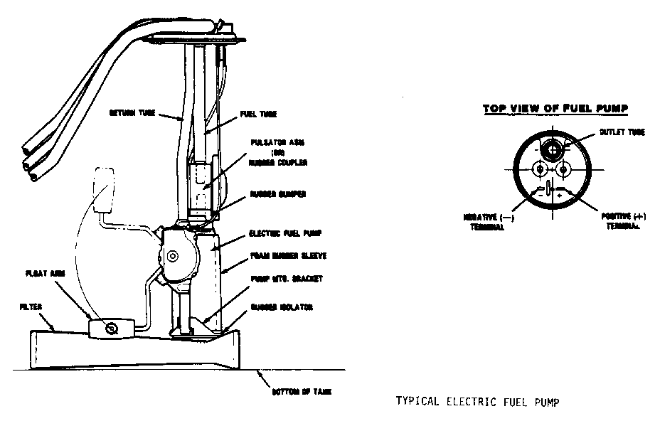
a. Note position of inlet filter on pump, then grasp filter and remove by rotating in one direction while pulling off. Refer to Figure.
b. Discomect electrical terminals from pump by gently prying up with edge of screwdriver blade.
c. Remove pump assembly by placing sender upside down on a bench. Grasp pump and pull downwards. Pull pump inlet out away from bracket.
Avoid bending the pump mounting bracket and the float arm when removing or installing pump.
d. Pull pump and pulsator off fuel tube.
e. Place rubber bumper and pulsator on new fuel pump. Position pulsator flat against bumper.
f. Place rubber isolator on pump inlet and install in same manner as removal; pulling downward on pump while fitting inlet into bracket.
g. Push pump upwards until rubber isolator and inlet are seated properly in bracket. Reposition foam rubber sleeve against rubber isolator if necessary.
h. Reconnect electrical terminals to the fuel pump. If terminals are loose on pump blades, remove and squeeze sides of terminals with pliers to obtain a tight fit.
i. Push pump upwards until rubber isolator and inlet are seated properly in bracket.
j. Install filter in the same position on the new electrical pump as removed one was on the original pump. Push the filter straight on by applying pressure to the outer edge of the metal ferrule being careful not to damage the filter. When properly installed, the plastic protrusion can be felt projecting beyond the metal ferrule.
k. Inspect pump to assure that it is properly seated in bracket.
4. Using new 0-ring, reinstall fuel pump and tank gauge sender assembly in tank.
5. Reinstall fuel tank assembly, being sure to properly attach the fuel feed, vapor and return hoses and electrical connector. Tighten all fuel line clamps to 1.5 N.M.. Torque the tank strap attaching bolts to 34 N.M. (25 lb. ft.).

General Motors bulletins are intended for use by professional technicians, not a "do-it-yourselfer". They are written to inform those technicians of conditions that may occur on some vehicles, or to provide information that could assist in the proper service of a vehicle. Properly trained technicians have the equipment, tools, safety instructions and know-how to do a job properly and safely. If a condition is described, do not assume that the bulletin applies to your vehicle, or that your vehicle will have that condition. See a General Motors dealer servicing your brand of General Motors vehicle for information on whether your vehicle may benefit from the information.
