For 1990-2009 cars only
Special Tools
J 8001 Dial Indicator Set
For equivalent regional tools, refer to Special Tools.
Note: The shimming procedure is required to be performed during service only when the following parts are replaced:
• The input shaft • The counter shaft • The main shaft • The adapter plate • The main housing • The extension housing
Input Shaft, Mainshaft, and Countershaft
- Rotate the clutch housing to the vertical position.
- Install the following assemblies in order:
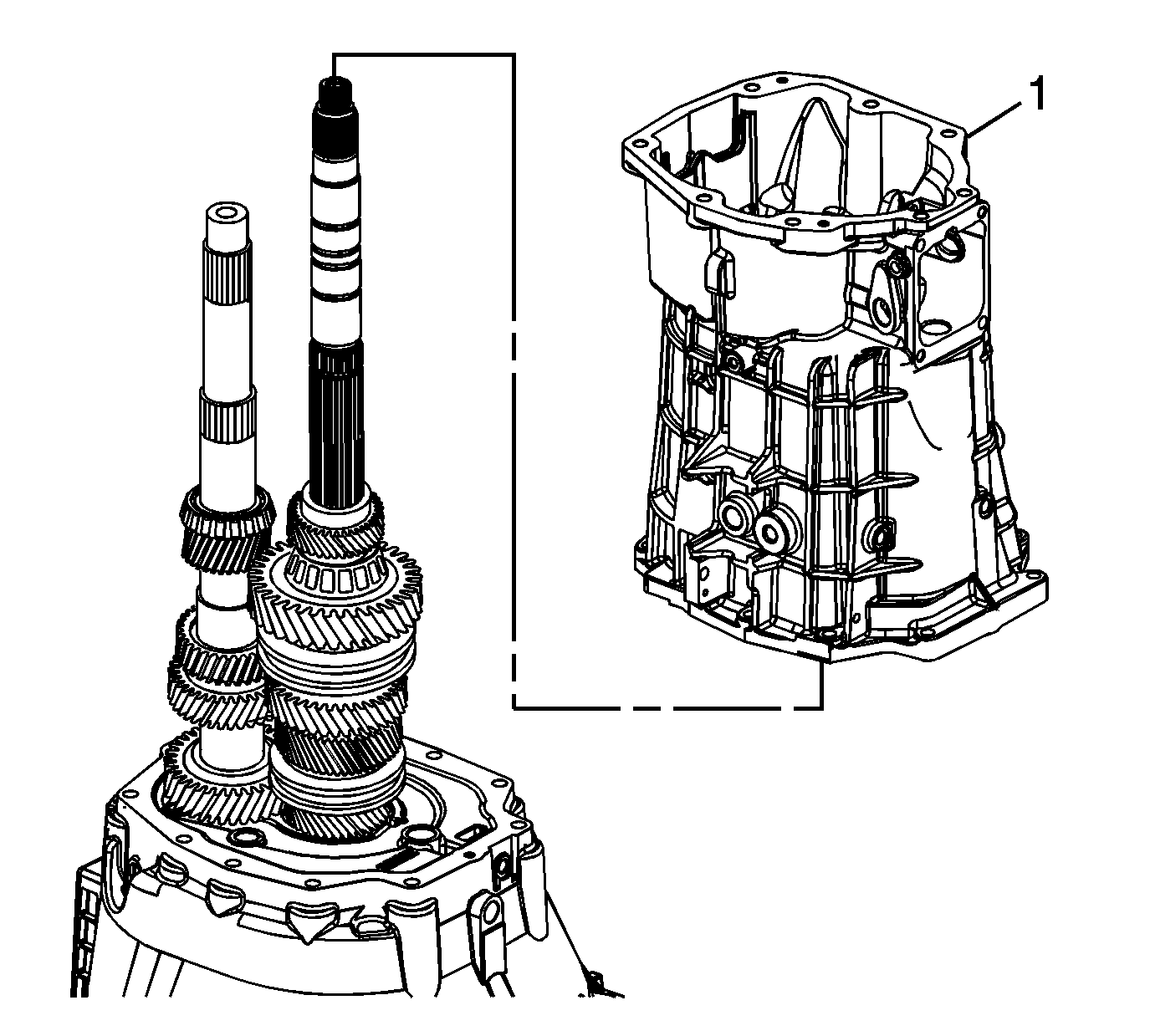
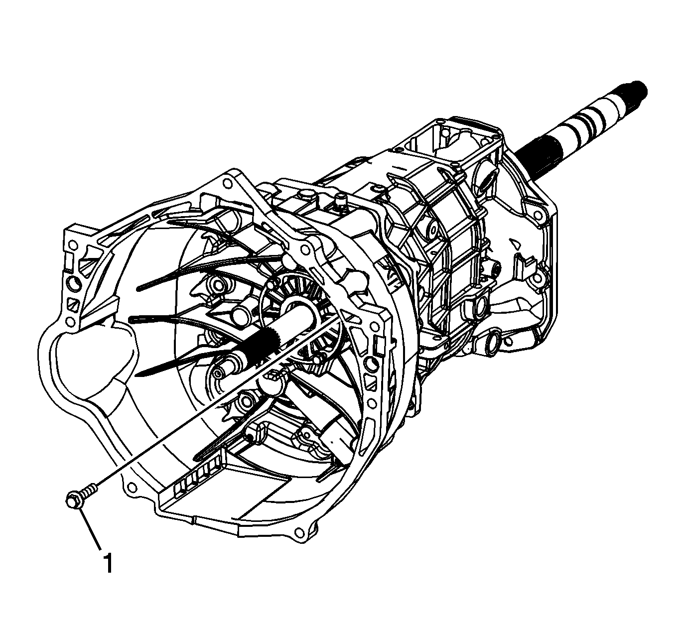
- Install the transmission case (1).
- Install the clutch housing to transmission case bolts and tighten to 36 N·m (27 Ib ft).
- Measure the input shaft/mainshaft end play using the following procedure:
- Select a shim to achieve 0.0127-0.0889 mm (0.00049-0.00349 in) preload.
- Remove the J 8001 indicator set .
- Measure the countershaft end play using the following procedure:
- Select a shim to achieve 0.0127-0.0889 mm (0.00049-0.00349 in) preload.
- Remove the J 8001 indicator set .
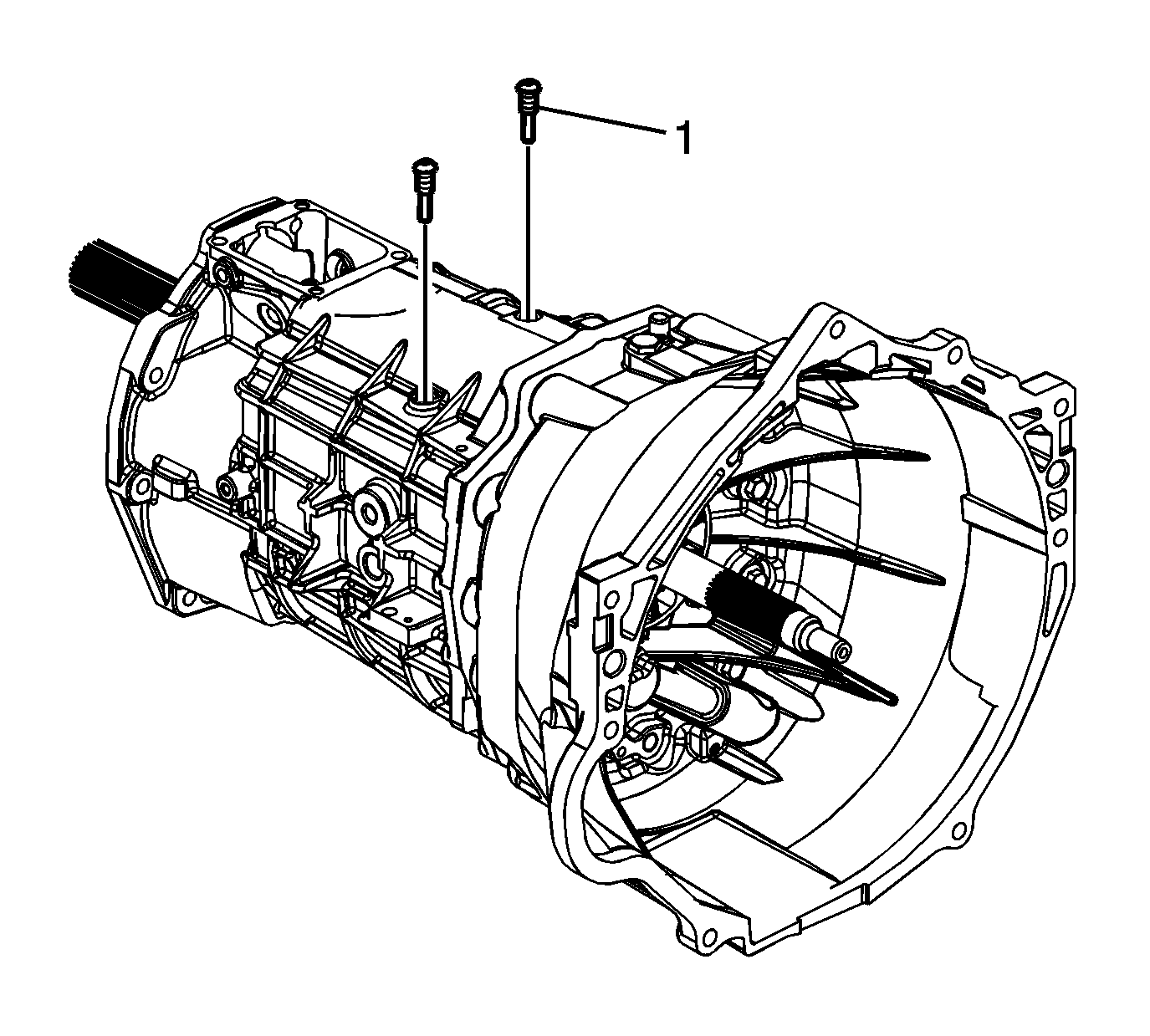
- Remove the shift lever guide bolts.
- Remove the clutch housing to the transmission case bolts.
- Remove the transmission case.
- Remove the following parts in order:
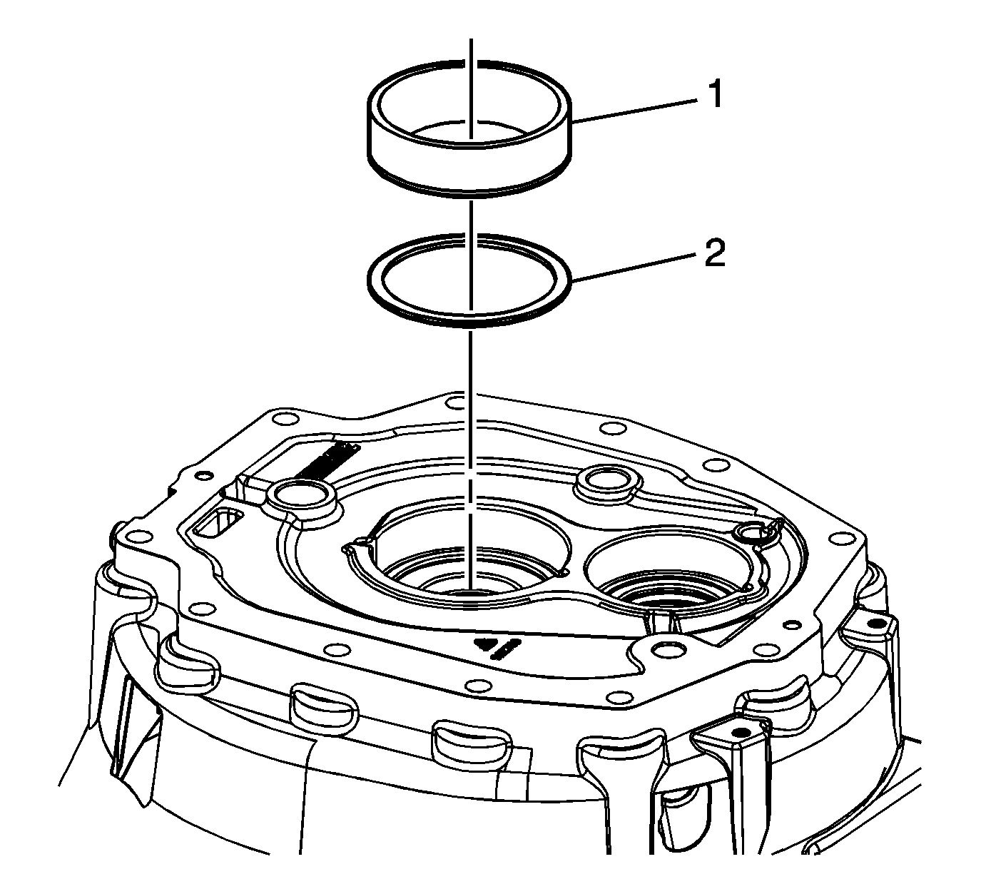
- Remove the input shaft bearing race (1).
- Remove the input shaft bearing shim (1) and discard.
- Install the new input shaft bearing shim, and the original bearing race.
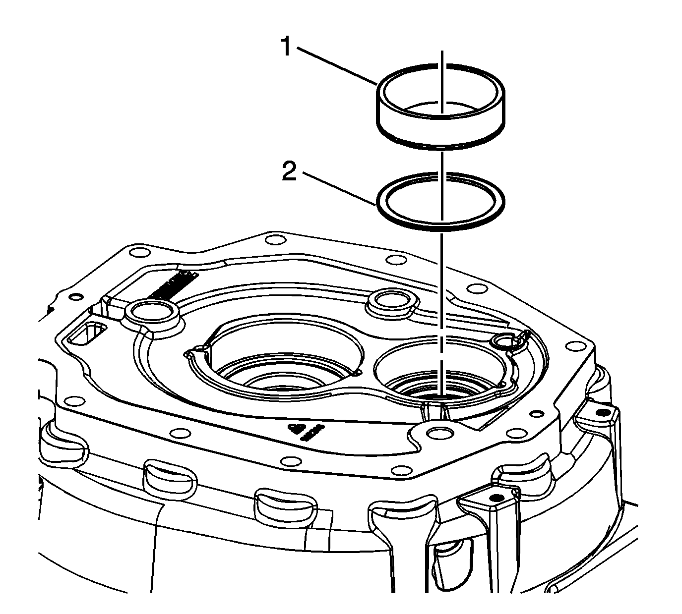
- Remove the countershaft bearing race (1).
- Remove the countershaft bearing shim (2) and discard.
- Install the new input shaft bearing shim, and the original bearing race.
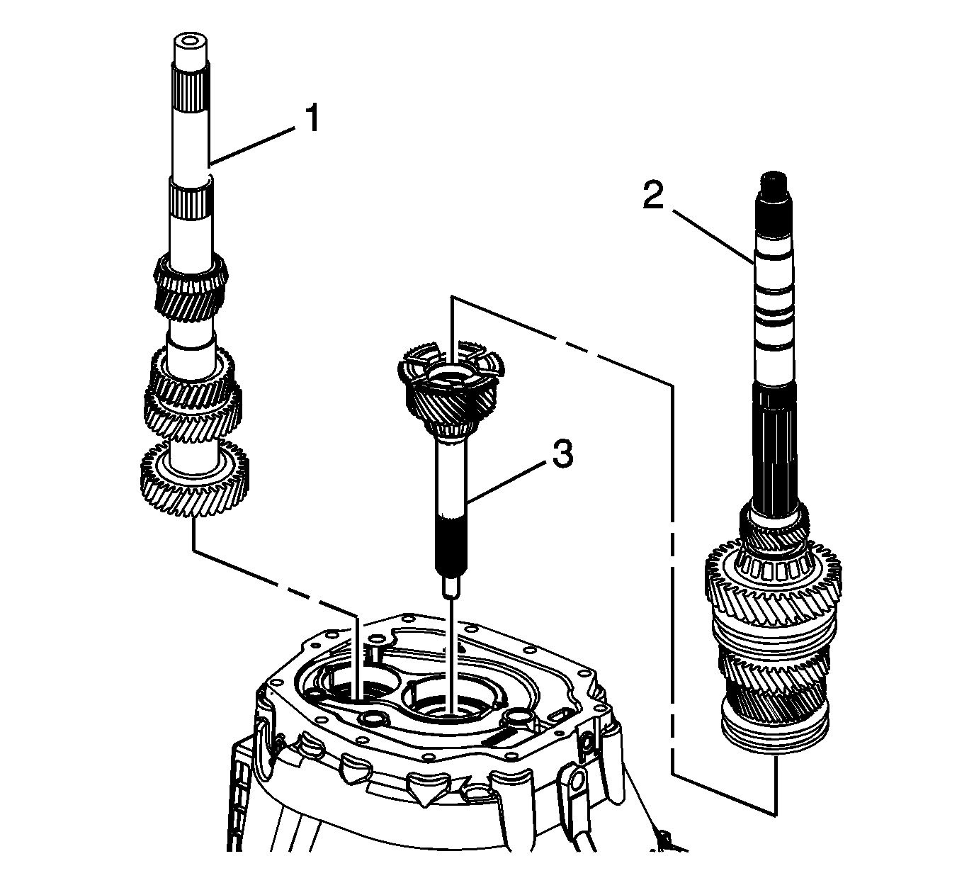
| 2.1. | The input shaft (3) |
| 2.2. | Align the 4th speed gear blocking ring to the input shaft. |
| 2.3. | The mainshaft assembly (2) |
| 2.4. | The countershaft (1), lifting up the mainshaft enough to install the countershaft. |
Caution: Refer to Fastener Caution in the Preface section.
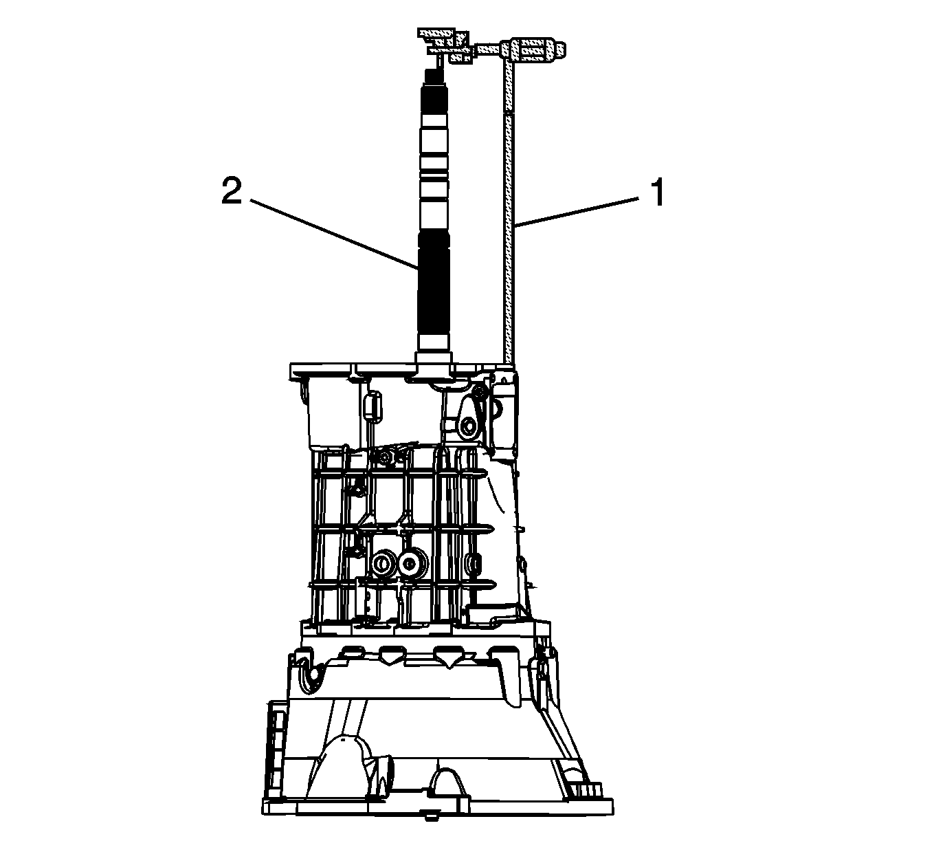
| 5.1. | Place the tip of the J 8001 indicator set (1) on the end of the mainshaft. |
| 5.2. | Move the main shaft up and down. |
| 5.3. | Record the measurement. |
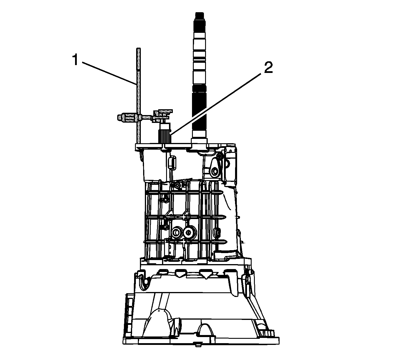
| 8.1. | Place the tip of the J 8001 indicator set (1) on the end of the countershaft. |
| 8.2. | Move the countershaft up and down. |
| 8.3. | Record the measurement. |
| 14.1. | The countershaft (1), lifting up the mainshaft (2) enough to remove the countershaft. |
| 14.2. | The mainshaft assembly (2) |
| 14.3. | The input shaft (3) |