Power Seats - Memory Switch Inoperative Memory Seat Inop, No DTC Set
Step | Action | Value(s) | Yes | No |
|---|---|---|---|---|
1 | Did you perform the Memory Seats System Check? | -- | Go to Step 2 | |
2 |
Does the driver seat operate properly when commanded by the scan tool? | -- | Go to Step 3 | Go to Step 4 |
3 | Replace the driver seat adjuster switch. Refer to Power Seat Switch Replacement . Is the replacement complete? | -- | Go to Step 15 | -- |
4 |
Is the measured voltage equal to the specified value? | B+ | Go to Step 6 | Go to Step 5 |
5 |
Is the repair complete? | -- | Go to Step 15 | -- |
6 | Use the DMM in order to measure the voltage between terminal 3 of connector C1 and a known good ground. Is the measured voltage equal to the specified value? | B+ | Go to Step 8 | Go to Step 7 |
7 |
Is the repair complete? | -- | Go to Step 15 | -- |
8 |
Is the measured voltage equal to the specified value? | B+ | Go to Step 10 | Go to Step 9 |
9 |
Is the repair complete? | -- | Go to Step 15 | -- |
10 | Use the DMM in order to measure the resistance between terminal 2 of the connector C1 and a known good ground. Is the measured resistance less than the specified value? | 5 ohms | Go to Step 12 | Go to Step 11 |
11 |
Is the repair complete? | -- | Go to Step 15 | -- |
12 | Use the DMM in order to measure the resistance between terminal 5 of the connector C1 and a known good ground. Is the measured resistance less than the specified value? | 5 ohms | Go to Step 14 | Go to Step 13 |
13 |
Is the repair complete? | -- | Go to Step 15 | -- |
14 | Replace the driver seat adjuster memory module. Refer to Memory Seat Control Module Replacement . Is the replacement complete? | -- | Go to Step 15 | -- |
15 |
Does the driver's memory seat operate properly? | -- | Go to Step 2 |
Power Seats - Memory Switch Inoperative Driver Switch Inop, DTC 21 Set
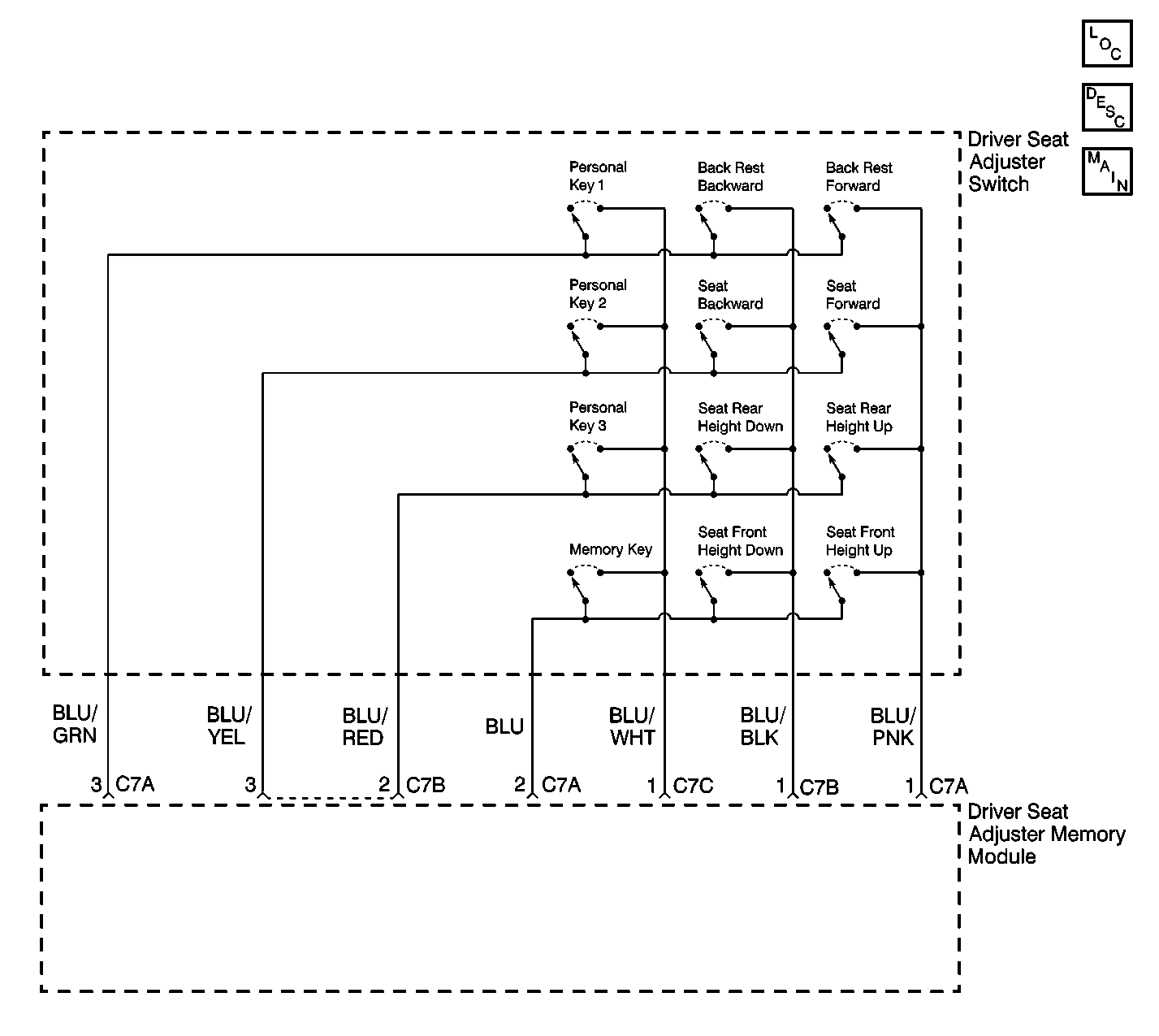
Circuit Description
The driver seat adjuster memory module monitors the voltage of the circuits to the driver seat adjuster switch. When the voltage value on these circuits is not within the specified value, the driver seat adjuster memory module will set DTC 21.
Conditions for Setting the DTC
DTC 21 will set if:
| • | the individual switches on the driver seat adjuster switch are shorted or jammed or its circuits are faulty. |
| • | the driver seat adjuster memory module is faulty. |
Action Taken When the DTC Sets
DTC 21 will set and the driver seat will become disabled.
Conditions for Clearing the DTC
DTC 21 will clear when the fault is no longer present.
Diagnostic Aids
| • | Check for liquid damage or any other type of physical damage that may have occurred to the driver seat adjuster switch. |
| • | Check for loose connections at the driver seat adjuster memory module. |
Test Description
The following numbers refer to the step numbers on the diagnostic table:
-
This step checks for a short between the terminals of the driver seat adjuster switch.
-
This step checks for a short between the terminals of the driver seat adjuster switch.
-
This step replaces the driver seat adjuster switch.
-
This step checks the individual switches of the driver seat adjuster switch.
-
This step checks the motor.
Step | Action | Value(s) | Yes | No | ||||||||||||||||||||||||||||||
|---|---|---|---|---|---|---|---|---|---|---|---|---|---|---|---|---|---|---|---|---|---|---|---|---|---|---|---|---|---|---|---|---|---|---|
1 | Was the Memory Seats System Check performed? | Go to Step 2 | ||||||||||||||||||||||||||||||||
Is the measured resistance within the specified value? | OL | Go to Step 3 | Go to Step 4 | |||||||||||||||||||||||||||||||
Is the measured resistance within the specified value? | Go to Step 5 | Go to Step 4 | ||||||||||||||||||||||||||||||||
Replace the driver seat adjuster switch. Refer to Power Seat Switch Replacement . Is the replacement complete? | -- | Go to Step 7 | -- | |||||||||||||||||||||||||||||||
Use the DMM in order to measure the resistance between the following terminals of the driver seat adjuster switch connector C7.
Is the measured resistance for all of the measurements less than the specified value? | 5 ohms | Go to Step 6 | Go to Step 4 | |||||||||||||||||||||||||||||||
Replace the driver seat adjuster memory module. Refer to Memory Seat Control Module Replacement . Is the replacement complete? | -- | Go to Step 7 | -- | |||||||||||||||||||||||||||||||
7 |
Does the driver seat operate properly in all directions and are there no DTC's present? | -- | System OK | Go to Step 1 |
