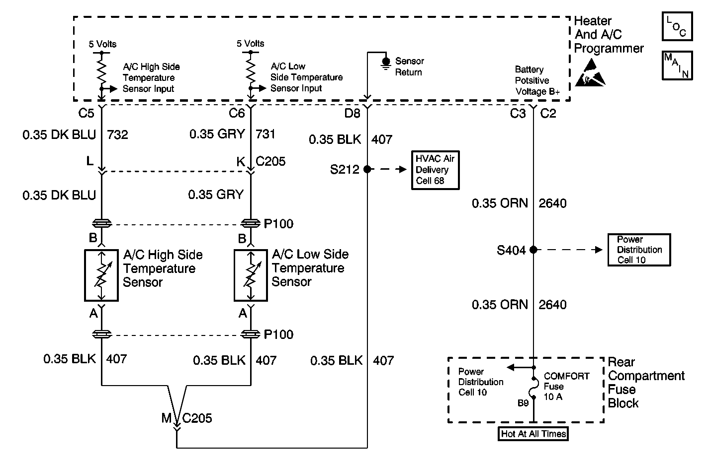
Circuit Description
The high side temperature sensor is a thermistor that controls the signal voltage to the heater and A/C programmer. The heater and A/C programmer supplies voltage on CKT 732. When the sensor is cold, the following conditions exist:
| • | The resistance is high. |
| • | The heater and A/C programmer reads a high signal voltage at pin C5. |
When the sensor warms, the following actions occur:
| • | The resistance is reduced |
| • | The signal voltage is pulled low through CKT 407. |
The signal voltage varies between 5 V (open circuit) and 0 V (short circuit).
Conditions for Running the DTC
| • | Turn the ignition to the ON position. The DTC B1310 is not set. |
| • | The ambient temperature is greater than -1°C (30°F). |
Action Taken When the DTC Sets
| • | The high cooling fans operate when the A/C compressor operation is possible. |
| • | A default value of 79°C (144°F) is substituted in order to continue the operation of the system. |
Notes On Intermittence
In some vehicles this DTC may set intermittently if the sensor temperature falls below -1°C (30°F). The DTC will become history after the sensor temperature increases.
If an intermittent DTC B1311 is set, connect the Scan Tool . Select the following options:
| • | Data list |
| • | Open/shorts data |
| • | Observe the reading |
Manipulate the wiring while observing the Scan Tool . If a failure is induced, the reading will jump. Inspect for the following conditions:
| • | Faulty terminal contact |
| • | An obstructed or defective sensor |
Test Description
-
The Scan Tool displays the high side temperature. Jumping the harness connector determines if the wiring or the sensor is the cause.
Step | Action | Value(s) | Yes | No |
|---|---|---|---|---|
Did you perform the Diagnostic System Check? | -- | Go to Step 2 | Go to Diagnostic System Check | |
Did the DTC change from B1312 to B1313? | -- | Go to Step 4 | Go to Step 3 | |
3 | Measure the voltage at terminal B. Is the measured voltage approximately equal to the specified value? | 5 V | Go to Step 6 | Go to Step 5 |
4 |
Did you complete the repair? | -- | Go to Diagnostic System Check | -- |
5 | Measure the voltage at terminal C5. Refer to Measuring Voltage in Wiring Systems. Is the measured voltage approximately equal to the specified value? | 5 V | Go to Step 8 | Go to Step 7 |
6 |
Did you complete the repair? | -- | Go to Diagnostic System Check | -- |
7 |
Did you complete the repair? | -- | Go to Diagnostic System Check | -- |
8 |
Did you complete the repair? | -- | Go to Diagnostic System Check | -- |
