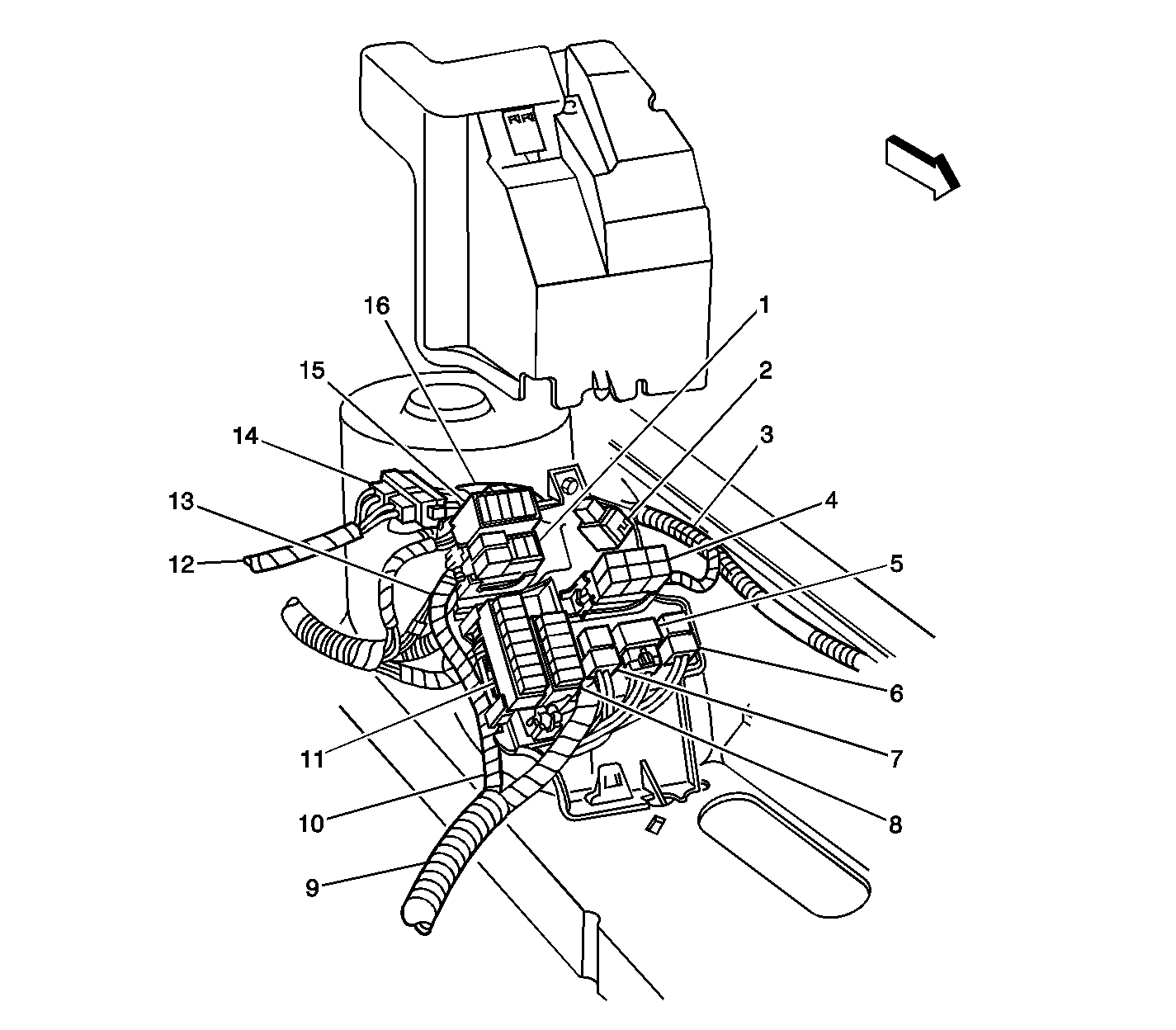
| Figure 1: |
Engine Compartment, on the Left Side
|
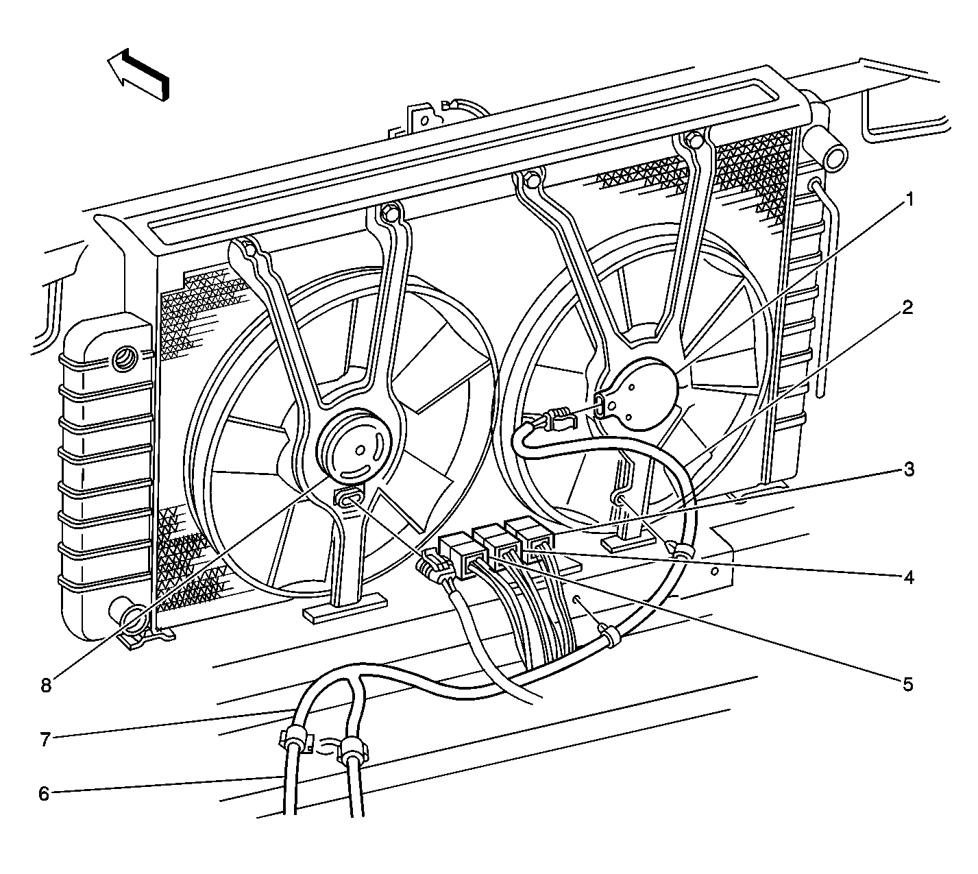
| Figure 2: |
Engine Compartment, Front
|
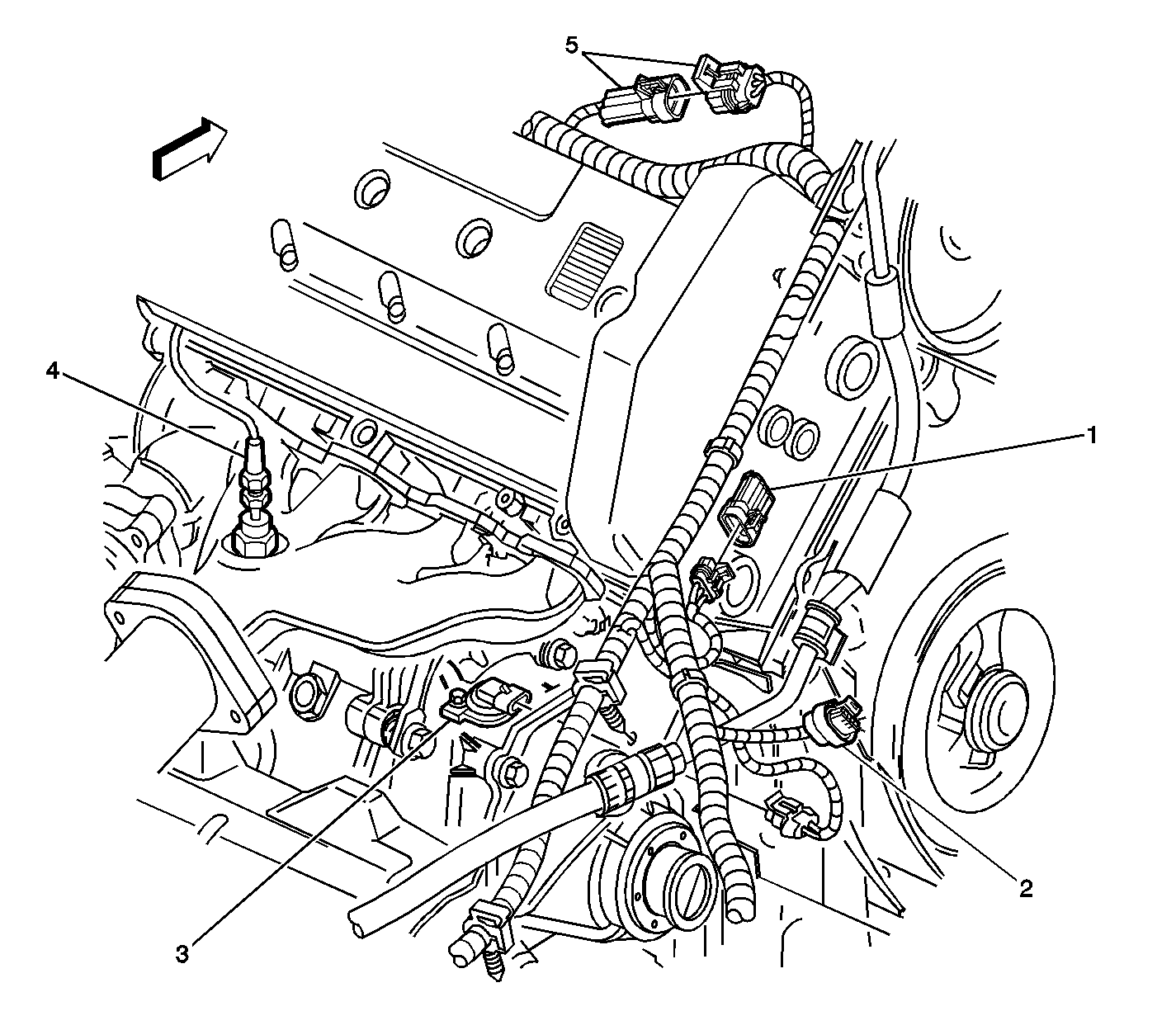
| Figure 3: |
Engine, Right Rear
|
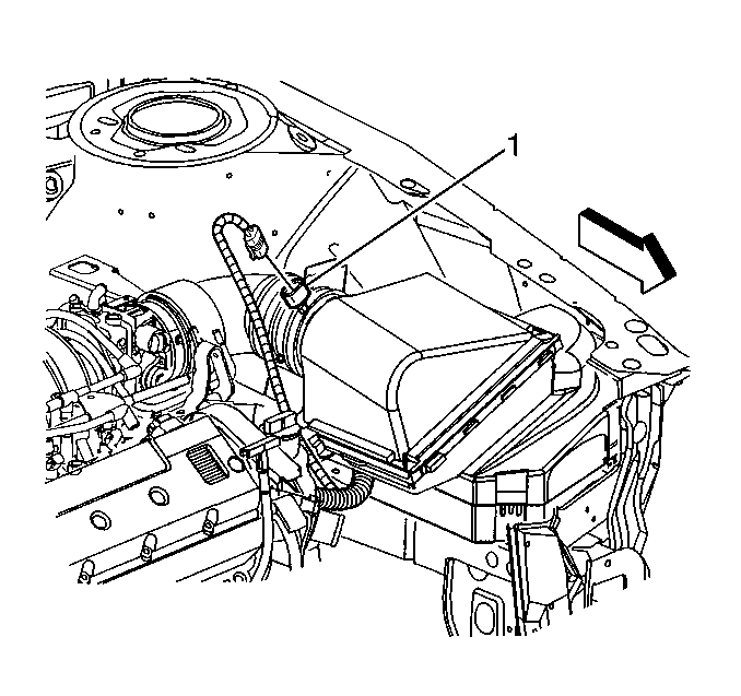
| Figure 4: |
Mass Air Flow (MAF) Sensor
|
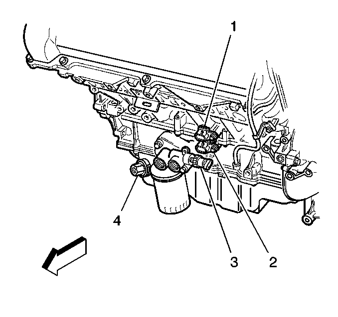
| Figure 5: |
CKP B, CKP A, Engine Oil Pressure (EOP) Switch, and Engine Oil Level
Switch
|
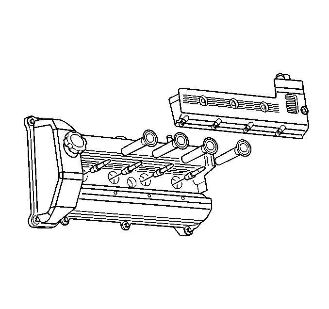
| Figure 6: |
Ignition Coil Bank 2
|
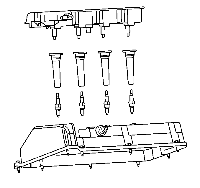
| Figure 7: |
Ignition Coil Bank 1
|
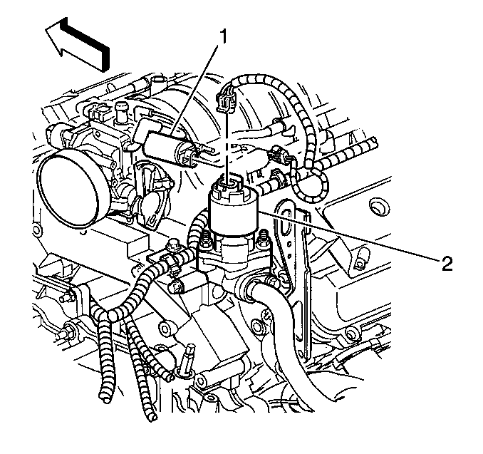
| Figure 8: |
Evaporative Emissions (EVAP) Canister Purge Solenoid, and EGR Valve
|
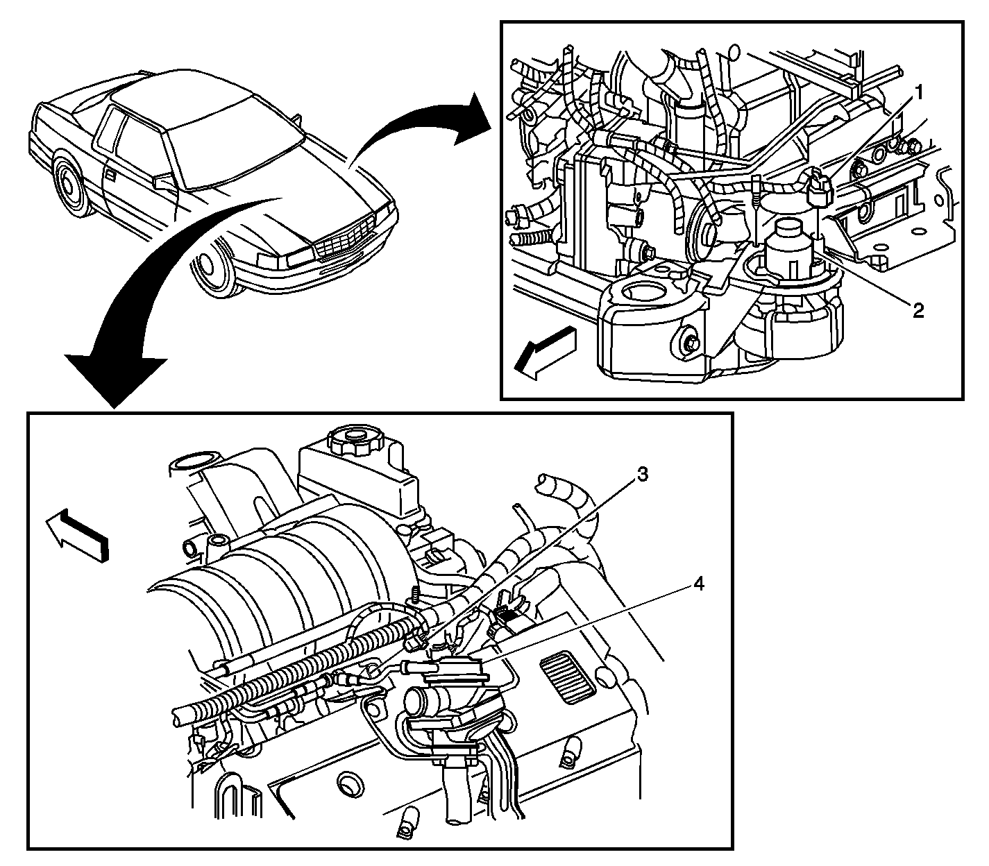
| Figure 9: |
Secondary Air Injection (AIR)
|
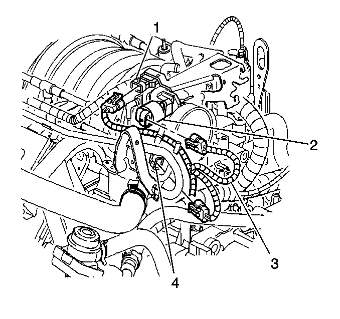
| Figure 10: |
MAP, IAC, ECT, TP Sensors
|
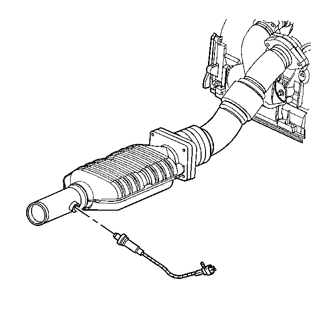
| Figure 11: |
Heated Oxygen Sensor (HO2S) Bank 1 Sensor 2
|
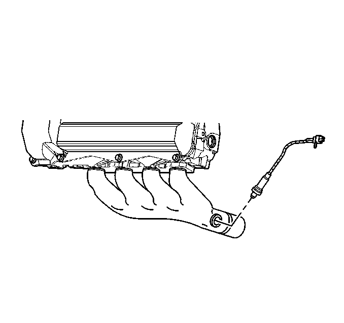
| Figure 12: |
Heated Oxygen Sensor (HO2S) Bank 2 Sensor 1
|
| Figure 13: |
Knock Sensor (KS)
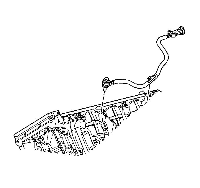
|
| Figure 14: |
Idle Air Control (IAC) Valve and Throttle Position (TP) Sensor
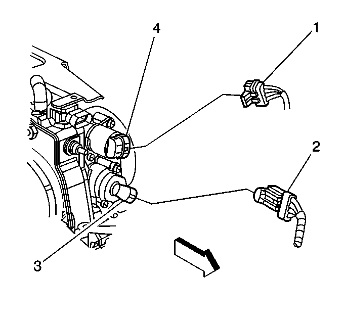
|
| Figure 15: |
Evaporative Emissions (EVAP) Canister, Fuel Tank, and Lines
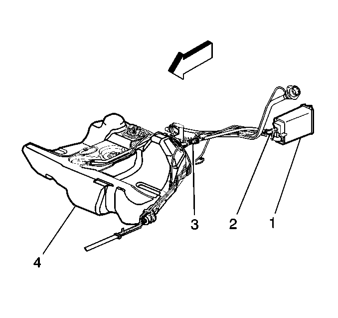
|
| Figure 16: |
Evaporative Emissions (EVAP) Canister and Lines
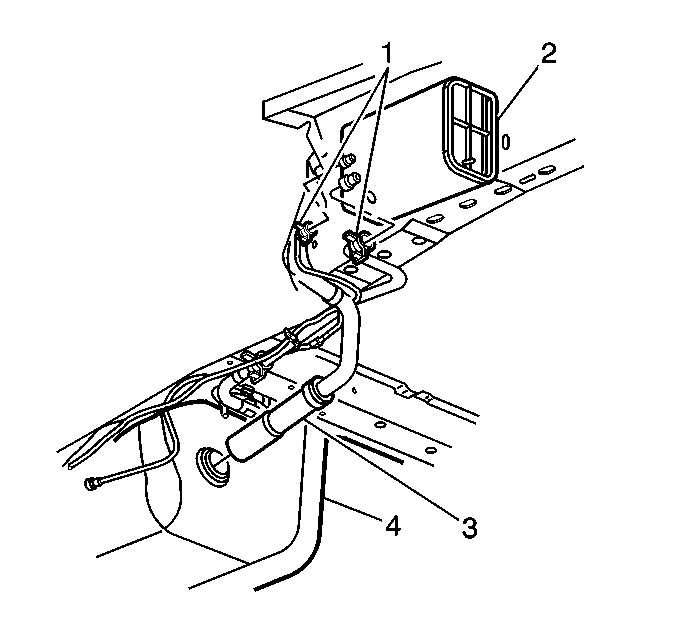
|
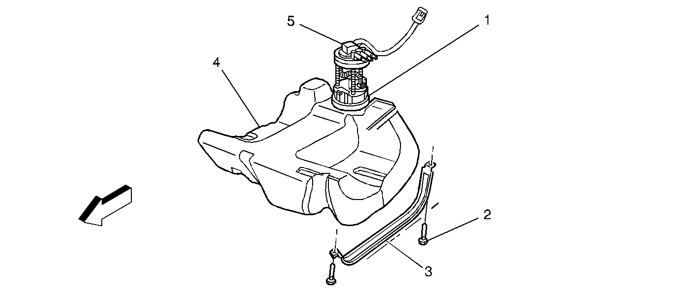
| Figure 17: |
Fuel Tank Pressure (FTP) Sensor, Fuel Pump and Sender Assembly
|
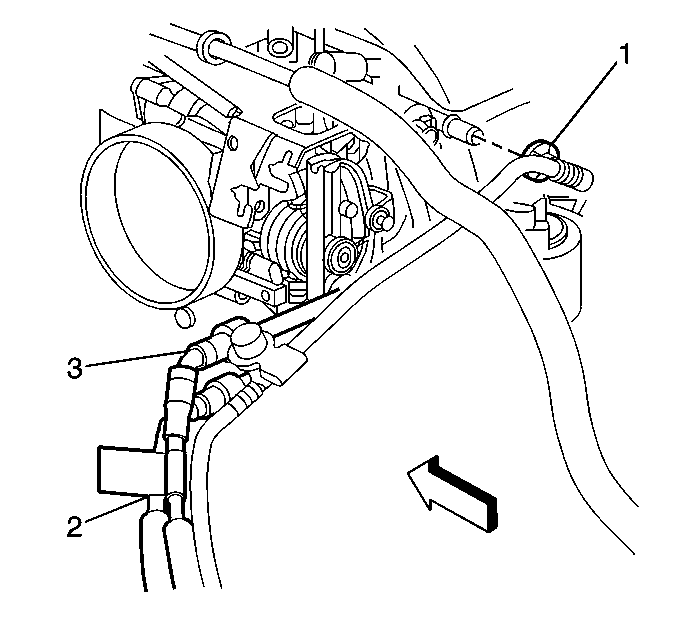
| Figure 18: |
Fuel Lines and Purge Lines
|
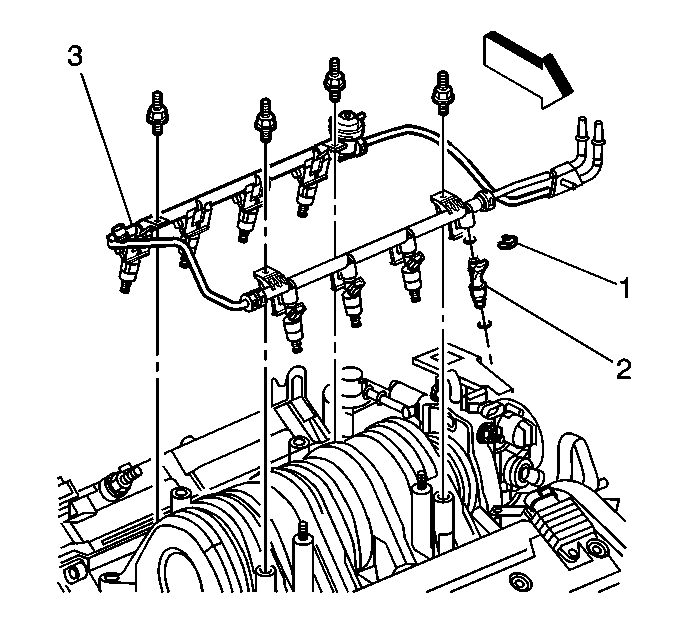
| Figure 19: |
Fuel Rail Assembly
|


