For 1990-2009 cars only
Water Outlet Replacement LH2
Removal Procedure
- Drain the cooling system. Refer to Cooling System Draining and Filling.
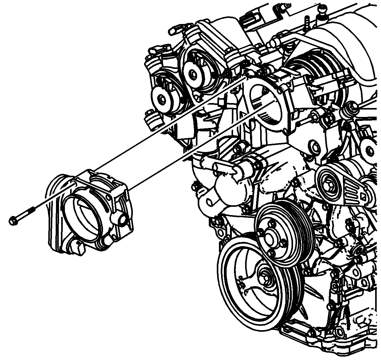
- Remove the throttle body. Refer to Throttle Body Assembly Replacement.
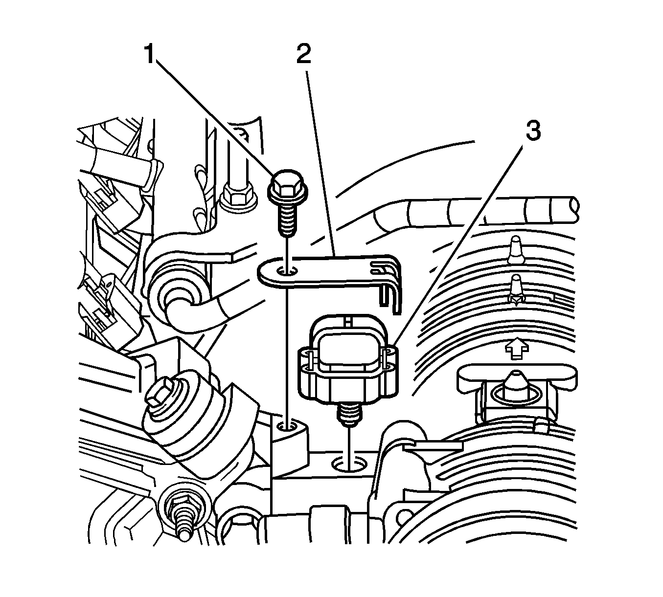
- Remove the manifold absolute pressure (MAP) sensor (3). Refer to Manifold Absolute Pressure Sensor Replacement.
- Disconnect the evaporative emission (EVAP) canister purge solenoid valve hose and electrical connector. Refer to Evaporative Emission Canister Purge Solenoid Valve Replacement.
- Compress the clamps and remove the following hoses from the thermostat and the tank:
- Loosen the intake manifold duct clamp (1).
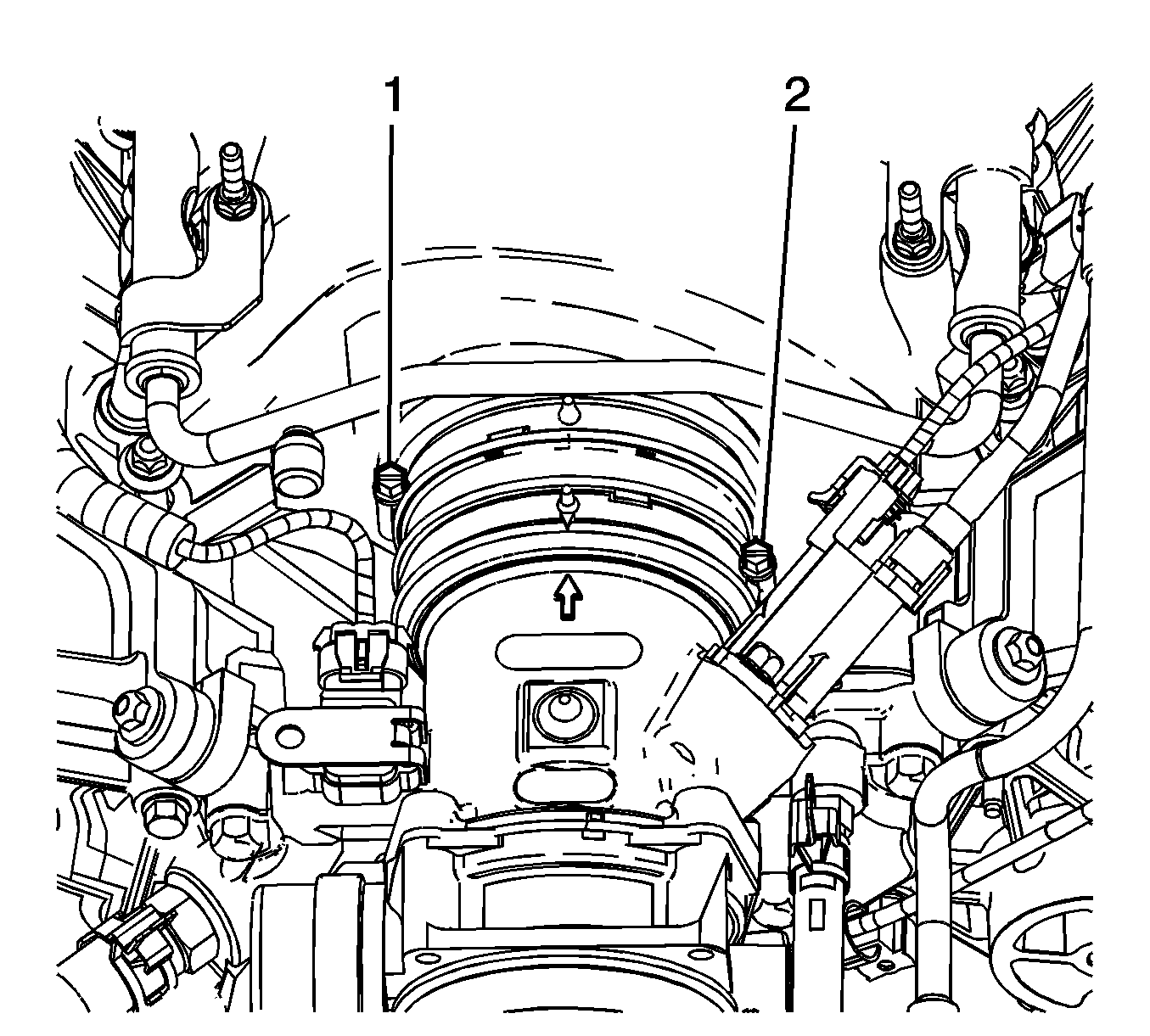
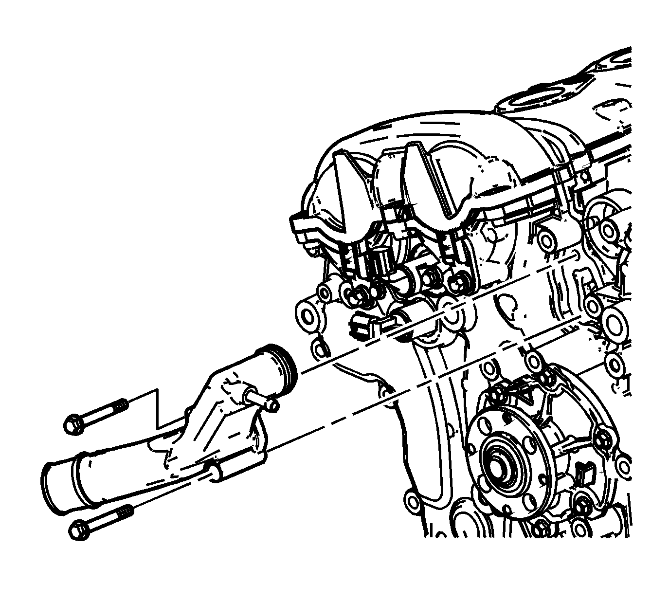
- Remove the bolts (1, 2) securing the water outlet housing to the cylinder heads.
- Remove the water outlet housing from the vehicle.
- Discard the water outlet housing gaskets.
- Clean and inspect the water outlet housing. Refer to Water Outlet Housing Cleaning and Inspection.
- Remove the following components from the water outlet housing if replacement is necessary:

| • | The heater inlet hose (1) |
| • | The radiator inlet hose (2) |
| • | The heater outlet hose (3) |
| • | The bypass hose (4) |
| • | The surge tank inlet hose |

| • | The intake manifold inlet duct and clamp |
| • | The surge tank inlet hose fitting |
| • | The heater inlet hose fitting |
| • | The evaporative emission (EVAP) canister purge solenoid valve--Refer to Evaporative Emission Canister Purge Solenoid Valve Replacement. |
Installation Procedure
- Install the following components to the water outlet housing if previously removed:
- Install new water outlet housing gaskets.
- Bolt (2) is approximately 10 mm longer than the other 3 bolts (1).
- Install the water outlet housing to the vehicle.
- Install the water outlet housing bolts.
- Tighten the intake manifold duct clamp (1).
- Compress the clamps and install the following hoses to the thermostat and the tank:
- Connect the evaporative emission (EVAP) canister purge solenoid valve hose and electrical connector. Refer to Evaporative Emission Canister Purge Solenoid Valve Replacement.
- Install the manifold absolute pressure (MAP) sensor (3). Refer to Manifold Absolute Pressure Sensor Replacement.
- Install the throttle body. Refer to Throttle Body Assembly Replacement.
- Fill the cooling system. Refer to Cooling System Draining and Filling.
Caution: Refer to Fastener Caution in the Preface section.
| • | The intake manifold inlet duct and clamp |
Tighten
Tighten the manifold inlet duct clamp to 6 N·m (53 lb in).
| • | The surge tank inlet hose fitting |
Tighten
Tighten the surge tank inlet hose fitting to 18 N·m (13 lb ft).
| • | The heater inlet hose fitting |
Tighten
Tighten the heater inlet hose fitting to 20 N·m (15 lb ft).
| • | The (EVAP) canister purge solenoid valve |
Tighten
Tighten the purge solenoid valve bolt to 12 N·m (106 lb in).
Note: The water outlet housing uses two different size bolts.
Tighten
Tighten the water outlet housing bolts to 25 N·m (18 lb ft).
Tighten
Tighten the intake manifold inlet duct clamp to 6 N·m (53 lb in).
| • | The heater inlet hose (1) |
| • | The radiator inlet hose (2) |
| • | The heater outlet hose (3) |
| • | The bypass hose (4) |
| • | The surge tank inlet hose |
Water Outlet Replacement LY7
Removal Procedure
- Partially drain the cooling system. Refer to Cooling System Draining and Filling.
- Remove the radiator hose from the water outlet. Refer to Radiator Inlet Hose Replacement.
- Remove the water outlet housing bolts.
- Remove the water outlet.
- Remove and discard the water outlet seals.
- Clean the water outlet housing sealing surfaces.
Installation Procedure
- Install new water outlet housing seals.
- Install the water outlet.
- Install the water outlet bolts.
- Install the radiator hose to the water outlet. Refer to Radiator Inlet Hose Replacement.
- Fill the cooling system. Refer to Cooling System Draining and Filling.
Caution: Refer to Fastener Caution in the Preface section.
Tighten
Tighten the water outlet housing bolts to 10 N·m(89 lb in).
