For 1990-2009 cars only
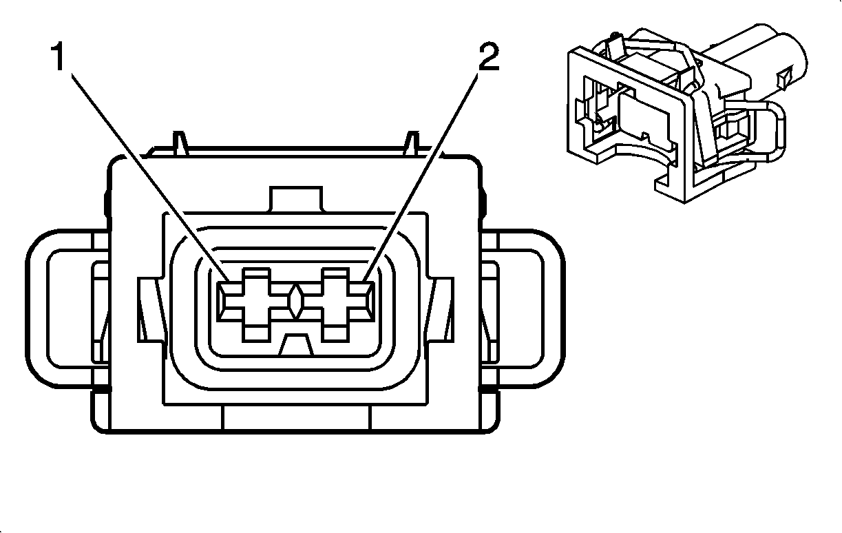
| Table 1: | After Boil Coolant Pump (V92) |
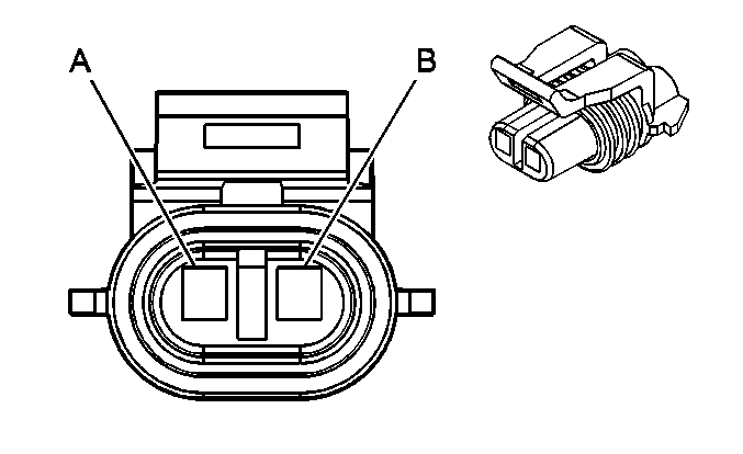
| Table 2: | Coolant Level Switch |
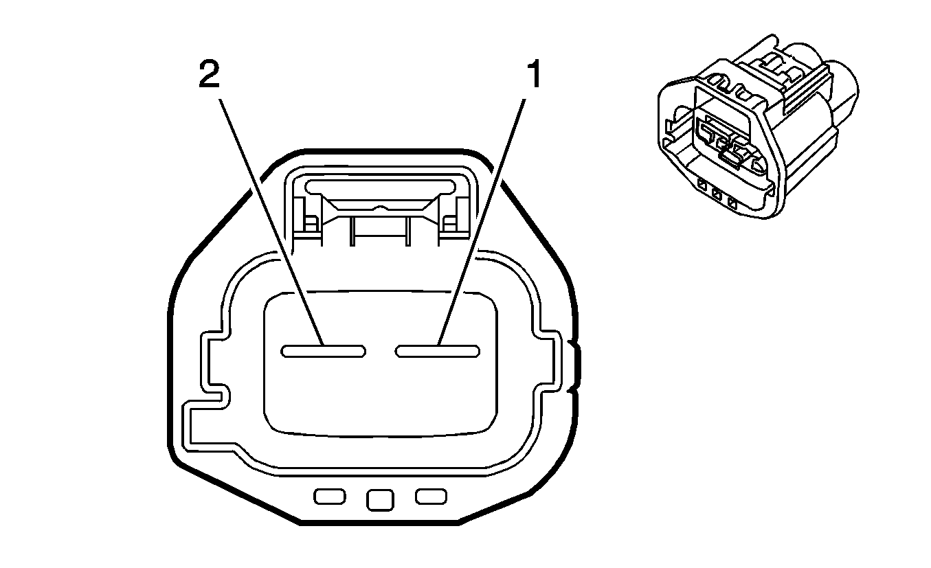
| Table 3: | Cooling Fan - Left |
| Table 4: | Cooling Fan - Right |

| |||||||
|---|---|---|---|---|---|---|---|
Connector Part Information |
| ||||||
Pin | Wire Color | Circuit No. | Function | ||||
1 | BK/WH | 1551 | Ground | ||||
2 | PK | 5126 | Afterboil Coolant Pump Relay Control | ||||

| |||||||
|---|---|---|---|---|---|---|---|
Connector Part Information |
| ||||||
Pin | Wire Color | Circuit No. | Function | ||||
A | L-GN | 1478 | Coolant Level Switch Signal | ||||
B | BK | 150 | Ground | ||||

| |||||||
|---|---|---|---|---|---|---|---|
Connector Part Information |
| ||||||
Pin | Wire Color | Circuit No. | Function | ||||
1 | GY | 532 | Cooling Fan Motor Supply Voltage | ||||
2 | WH | 504 | Cooling Fan Low Reference | ||||

| |||||||
|---|---|---|---|---|---|---|---|
Connector Part Information |
| ||||||
Pin | Wire Color | Circuit No. | Function | ||||
1 | L-BU | 409 | Cooling Fan Motor Supply Voltage | ||||
2 | BK | 250 | Ground | ||||
