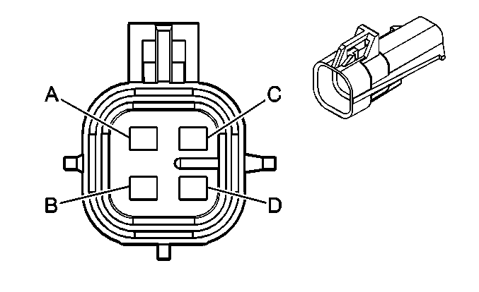
| |||||||
|---|---|---|---|---|---|---|---|
Connector Part Information |
| ||||||
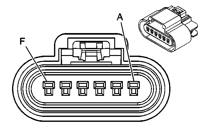
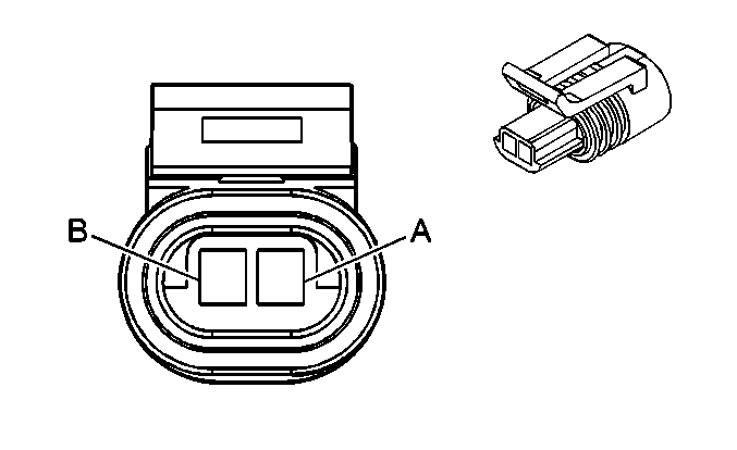
Pin | Wire Color | Circuit No. | Function | ||||
A | PU | 1272 | Low Reference | ||||
B | L-BU | 1162 | APP Sensor 2 Signal | ||||
C | TN | 1274 | 5-Volt Reference | ||||
D | BN | 1271 | Low Reference | ||||
E | D-BU | 1161 | APP Sensor 1 Signal | ||||
F | WH/BK | 1164 | 5-Volt Reference | ||||
| |||||||
|---|---|---|---|---|---|---|---|
Connector Part Information |
| ||||||
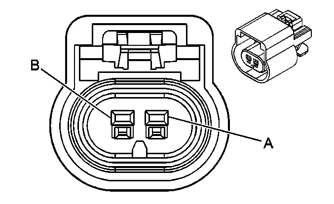
Pin | Wire Color | Circuit No. | Function | ||||
A | BK | 1551 | Ground | ||||
B | L-GN | 5282 | CMP Actuator Solenoid Control Exhaust Bank 1 | ||||
|
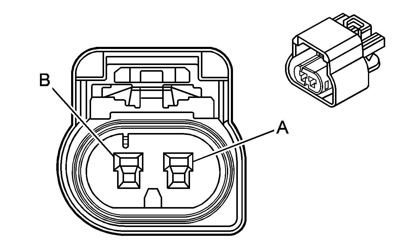
| |||||||
|---|---|---|---|---|---|---|---|
Connector Part Information |
| ||||||
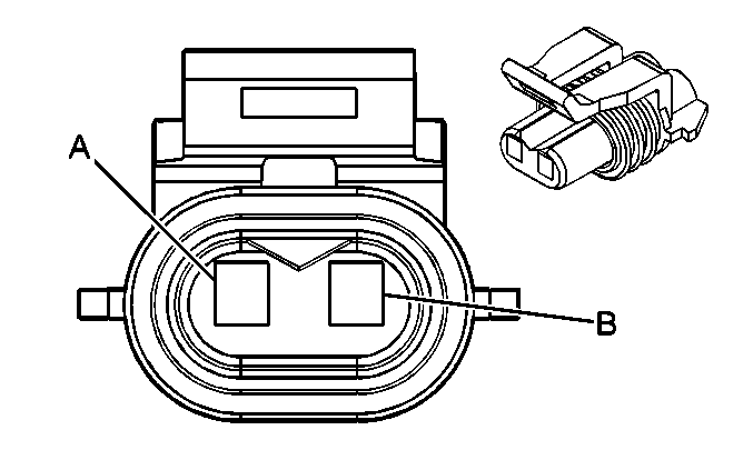
Pin | Wire Color | Circuit No. | Function | ||||
A | BK | 1551 | Ground | ||||
B | WH | 5283 | CMP Actuator Solenoid Control Exhaust Bank 2 | ||||
|
| |||||||
|---|---|---|---|---|---|---|---|
Connector Part Information |
| ||||||
Pin | Wire Color | Circuit No. | Function | ||||
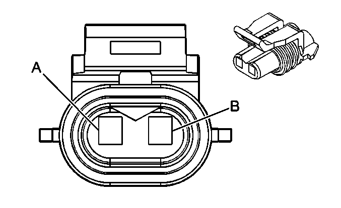
A | BK | 1551 | Ground | ||||
B | PU | 5284 | CMP Actuator Solenoid Control Intake Bank 1 | ||||
|
| |||||||
|---|---|---|---|---|---|---|---|
Connector Part Information |
| ||||||
Pin | Wire Color | Circuit No. | Function | ||||
A | BK | 1551 | Ground | ||||
B | OG/BK | 5272 | CMP Actuator Solenoid Control Intake Bank 2 | ||||
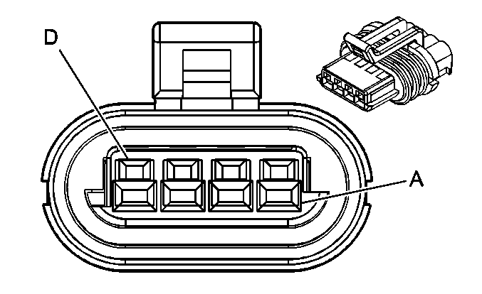
| |||||||
|---|---|---|---|---|---|---|---|
Connector Part Information |
| ||||||
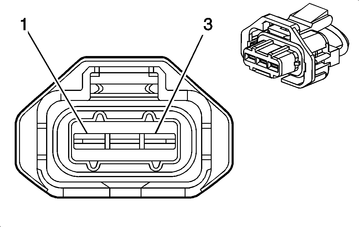
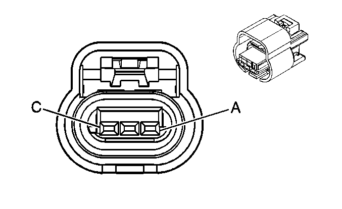
Pin | Wire Color | Circuit No. | Function | ||||
1 | D-GN | 5273 | CMP Sensor Signal Exhaust Bank 1 | ||||
2 | GY | 5296 | Low Reference | ||||
3 | YE/BK | 5297 | 12-Volt Reference | ||||
|
| |||||||
|---|---|---|---|---|---|---|---|
Connector Part Information |
| ||||||
Pin | Wire Color | Circuit No. | Function | ||||
1 | PU | 5274 | CMP Sensor Signal Exhaust Bank 2 | ||||
2 | BN | 5299 | Low Reference | ||||
3 | L-GN | 5298 | 12-Volt Reference | ||||
|
| |||||||
|---|---|---|---|---|---|---|---|
Connector Part Information |
| ||||||
Pin | Wire Color | Circuit No. | Function | ||||
1 | OG | 5275 | CMP Sensor Signal Intake Bank 1 | ||||
2 | TN | 5301 | Low Reference | ||||
3 | D-BU | 5300 | 12-Volt Reference | ||||
|
| |||||||
|---|---|---|---|---|---|---|---|
Connector Part Information |
| ||||||
Pin | Wire Color | Circuit No. | Function | ||||
1 | YE | 5276 | CMP Sensor Signal Intake Bank 2 | ||||
2 | BN/WH | 5303 | Low Reference | ||||
3 | L-BU | 5302 | 12-Volt Reference | ||||
| |||||||
|---|---|---|---|---|---|---|---|
Connector Part Information |
| ||||||
Pin | Wire Color | Circuit No. | Function | ||||
1 | L-GN | 1867 | 12-Volt Reference | ||||
2 | YE | 573 | CKP Sensor 1 Signal | ||||
3 | PU | 574 | Low Reference | ||||
| |||||||
|---|---|---|---|---|---|---|---|
Connector Part Information |
| ||||||
Pin | Wire Color | Circuit No. | Function | ||||
A | YE | 410 | ECT Sensor Signal | ||||
B | TN | 2761 | Low Reference | ||||
| |||||||
|---|---|---|---|---|---|---|---|
Connector Part Information |
| ||||||
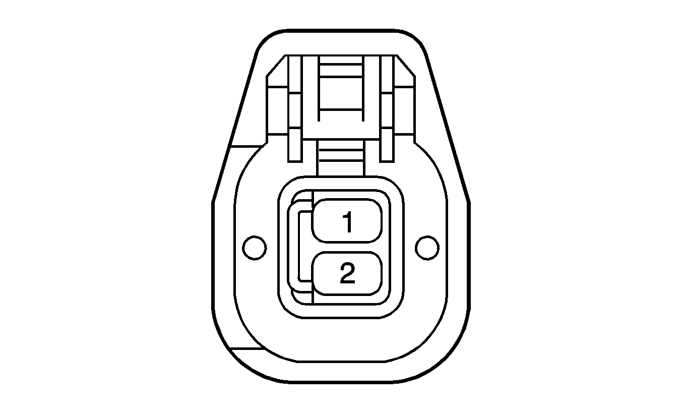
Pin | Wire Color | Circuit No. | Function | ||||
A | BK | 2755 | Low Reference | ||||
B | TN/WH | 331 | Oil Pressure Sensor Signal | ||||
C | GY | 2705 | 5-Volt Reference A | ||||
| |||||||
|---|---|---|---|---|---|---|---|
Connector Part Information |
| ||||||
Pin | Wire Color | Circuit No. | Function | ||||
A | PK/BK | 5290 | Ignition 1 Voltage | ||||
B | D-GN/WH | 428 | EVAP Canister Purge Solenoid Control | ||||
| |||||||
|---|---|---|---|---|---|---|---|
Connector Part Information |
| ||||||
Pin | Wire Color | Circuit No. | Function | ||||
A | OG | 1540 | Battery Positive Voltage | ||||
B | WH | 1310 | EVAP Canister Vent Solenoid Control | ||||
| |||||||
|---|---|---|---|---|---|---|---|
Connector Part Information |
| ||||||
Pin | Wire Color | Circuit No. | Function | ||||
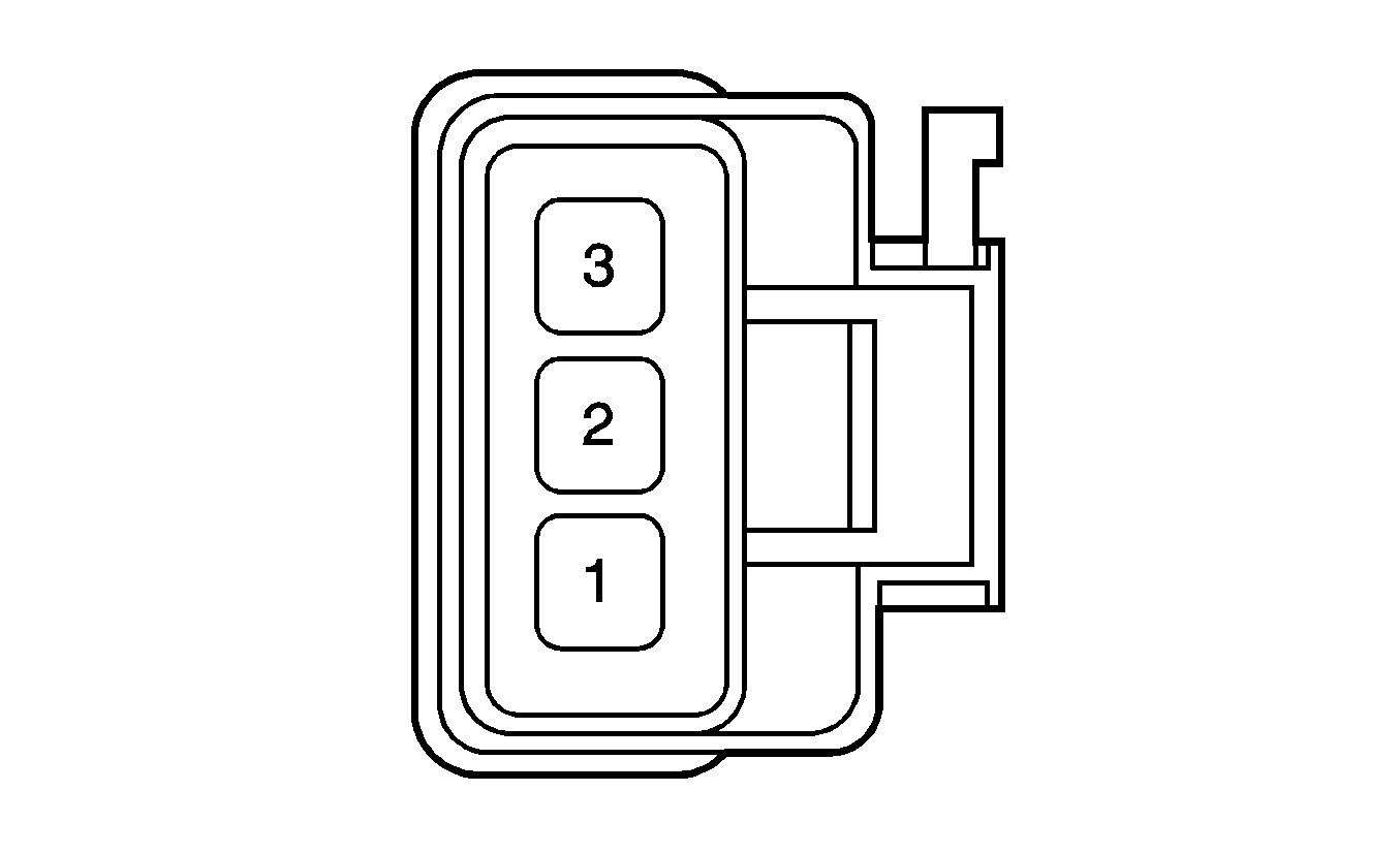
1 | PK/BK | 5291 | Ignition 1 Voltage | ||||
2 | TN | 1744 | Fuel Injector 1 Control | ||||
|
| |||||||
|---|---|---|---|---|---|---|---|
Connector Part Information |
| ||||||
Pin | Wire Color | Circuit No. | Function | ||||
1 | PK/BK | 5292 | Ignition 1 Voltage | ||||
2 | OG/BK | 1745 | Fuel Injector 2 Control | ||||
|
| |||||||
|---|---|---|---|---|---|---|---|
Connector Part Information |
| ||||||
Pin | Wire Color | Circuit No. | Function | ||||
1 | PK/BK | 5291 | Ignition 1 Voltage | ||||
2 | L-BU/BK | 1746 | Fuel Injector 3 Control | ||||
|
| |||||||
|---|---|---|---|---|---|---|---|
Connector Part Information |
| ||||||
Pin | Wire Color | Circuit No. | Function | ||||
1 | PK/BK | 5292 | Ignition 1 Voltage | ||||
2 | YE/BK | 844 | Fuel Injector 4 Control | ||||
|
| |||||||
|---|---|---|---|---|---|---|---|
Connector Part Information |
| ||||||
Pin | Wire Color | Circuit No. | Function | ||||
1 | PK/BK | 5291 | Ignition 1 Voltage | ||||
2 | L-GN/BK | 845 | Fuel Injector 5 Control | ||||
|
| |||||||
|---|---|---|---|---|---|---|---|
Connector Part Information |
| ||||||
Pin | Wire Color | Circuit No. | Function | ||||
1 | PK/BK | 5292 | Ignition 1 Voltage | ||||
2 | YE/BK | 846 | Fuel Injector 6 Control | ||||
|
| |||||||
|---|---|---|---|---|---|---|---|
Connector Part Information |
| ||||||
Pin | Wire Color | Circuit No. | Function | ||||
1 | PK/BK | 5291 | Ignition 1 Voltage | ||||
2 | OG/BK | 877 | Fuel Injector 7 Control | ||||
|
| |||||||
|---|---|---|---|---|---|---|---|
Connector Part Information |
| ||||||
Pin | Wire Color | Circuit No. | Function | ||||
1 | PK/BK | 5292 | Ignition 1 Voltage | ||||
2 | D-BU/WH | 878 | Fuel Injector 8 Control | ||||
| |||||||
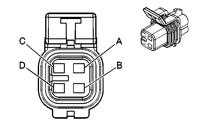
|---|---|---|---|---|---|---|---|
Connector Part Information |
| ||||||
Pin | Wire Color | Circuit No. | Function | ||||
A | L-BU | 1937 | Fuel Level Sensor Signal - Primary | ||||
B | GY | 120 | Fuel Pump Supply Voltage | ||||
C | BK | 1050 | Ground | ||||
D | TN | 452 | Low Reference | ||||
| |||||||
|---|---|---|---|---|---|---|---|
Connector Part Information |
| ||||||
Pin | Wire Color | Circuit No. | Function | ||||
A | TN | 452 | Low Reference | ||||
B | D-GN | 890 | Fuel Tank Pressure Sensor Signal | ||||
C | GY/BK | 2709 | 5-Volt Reference | ||||
| |||||||
|---|---|---|---|---|---|---|---|
Connector Part Information |
| ||||||
Pin | Wire Color | Circuit No. | Function | ||||
1 | PU | 1666 | HO2S Reference Voltage Bank 1 Sensor 1 | ||||
2 | PU/WH | 5281 | HO2S Output Pump Current Bank 1 Sensor 1 | ||||
3 | PK/BK | 5293 | Ignition 1 Voltage | ||||
4 | PU/WH | 5037 | HO2S Heater Low Control Bank 1 Sensor 1 | ||||
5 | TN | 1667 | HO2S Low Reference Bank 1 Sensor 1 | ||||
6 | OG | 5280 | HO2S Input Pump Current Bank 1 Sensor 1 | ||||
| |||||||
|---|---|---|---|---|---|---|---|
Connector Part Information |
| ||||||
Pin | Wire Color | Circuit No. | Function | ||||
A | TN | 1671 | HO2S Low Signal Bank 1 Sensor 2 | ||||
B | PU | 1670 | HO2S High Signal Bank 1 Sensor 2 | ||||
C | YE | 5036 | HO2S Heater Low Control Bank 1 Sensor 2 | ||||
D | PK/BK | 5294 | Ignition 1 Voltage | ||||
|
| |||||||
|---|---|---|---|---|---|---|---|
Connector Part Information |
| ||||||
Pin | Wire Color | Circuit No. | Function | ||||
1 | PU/WH | 1665 | HO2S Reference Voltage Bank 2 Sensor 1 | ||||
2 | WH | 5279 | HO2S Output Pump Current Bank 2 Sensor 1 | ||||
3 | PK/BK | 5293 | Ignition 1 Voltage | ||||
4 | L-BU | 5038 | HO2S Heater Low Control Bank 2 Sensor 1 | ||||
5 | TN/WH | 1653 | HO2S Low Reference Bank 2 Sensor 1 | ||||
6 | L-GN | 5278 | HO2S Input Pump Current Bank 2 Sensor 1 | ||||
|
| |||||||
|---|---|---|---|---|---|---|---|
Connector Part Information |
| ||||||
Pin | Wire Color | Circuit No. | Function | ||||
A | TN/WH | 1669 | HO2S Low Signal Bank 2 Sensor 2 | ||||
B | PU/WH | 1668 | HO2S High Signal Bank 2 Sensor 2 | ||||
C | PU | 5035 | HO2S Heater Low Control Bank 2 Sensor 2 | ||||
D | PK/BK | 5294 | Ignition 1 Voltage | ||||
| |||||||
|---|---|---|---|---|---|---|---|
Connector Part Information |
| ||||||
Pin | Wire Color | Circuit No. | Function | ||||
A | PK | 5291 | Ignition 1 Voltage | ||||
B | PU | 2121 | IC 1 Control | ||||
C | BN | 2129 | Low Reference | ||||
D | BK | 1451 | Ground | ||||
|
| |||||||
|---|---|---|---|---|---|---|---|
Connector Part Information |
| ||||||
Pin | Wire Color | Circuit No. | Function | ||||
A | PK | 5292 | Ignition 1 Voltage | ||||
B | RD | 2122 | IC 2 Control | ||||
C | BN | 2130 | Low Reference | ||||
D | BK | 1451 | Ground | ||||
|
| |||||||
|---|---|---|---|---|---|---|---|
Connector Part Information |
| ||||||
Pin | Wire Color | Circuit No. | Function | ||||
A | PK | 5291 | Ignition 1 Voltage | ||||
B | L-BU | 2123 | IC 3 Control | ||||
C | BN | 2129 | Low Reference | ||||
D | BK | 1451 | Ground | ||||
|
| |||||||
|---|---|---|---|---|---|---|---|
Connector Part Information |
| ||||||
Pin | Wire Color | Circuit No. | Function | ||||
A | PK | 5292 | Ignition 1 Voltage | ||||
B | D-GN | 2124 | IC 4 Control | ||||
C | BN | 2130 | Low Reference | ||||
D | BK | 1451 | Ground | ||||
|
| |||||||
|---|---|---|---|---|---|---|---|
Connector Part Information |
| ||||||
Pin | Wire Color | Circuit No. | Function | ||||
A | PK | 5291 | Ignition 1 Voltage | ||||
B | D-GN | 2125 | IC 5 Control | ||||
C | BN | 2129 | Low Reference | ||||
D | BK | 1451 | Ground | ||||
|
| |||||||
|---|---|---|---|---|---|---|---|
Connector Part Information |
| ||||||
Pin | Wire Color | Circuit No. | Function | ||||
A | PK | 5292 | Ignition 1 Voltage | ||||
B | L-BU | 2126 | IC 6 Control | ||||
C | BN | 2130 | Low Reference | ||||
D | BK | 1451 | Ground | ||||
|
| |||||||
|---|---|---|---|---|---|---|---|
Connector Part Information |
| ||||||
Pin | Wire Color | Circuit No. | Function | ||||
A | PK | 5291 | Ignition 1 Voltage | ||||
B | RD | 2127 | IC 7 Control | ||||
C | BN | 2129 | Low Reference | ||||
D | BK | 1451 | Ground | ||||
|
| |||||||
|---|---|---|---|---|---|---|---|
Connector Part Information |
| ||||||
Pin | Wire Color | Circuit No. | Function | ||||
A | PK | 5292 | Ignition 1 Voltage | ||||
B | PU | 2128 | IC 8 Control | ||||
C | BN | 2130 | Low Reference | ||||
D | BK | 1451 | Ground | ||||
| |||||||
|---|---|---|---|---|---|---|---|
Connector Part Information |
| ||||||
Pin | Wire Color | Circuit No. | Function | ||||
A | D-BU | 496 | Knock Sensor 1 Signal | ||||
B | GY | 1716 | Low Reference | ||||
|
| |||||||
|---|---|---|---|---|---|---|---|
Connector Part Information |
| ||||||
Pin | Wire Color | Circuit No. | Function | ||||
A | L-BU | 1876 | Knock Sensor 2 Signal | ||||
B | GY | 2303 | Low Reference | ||||
| |||||||
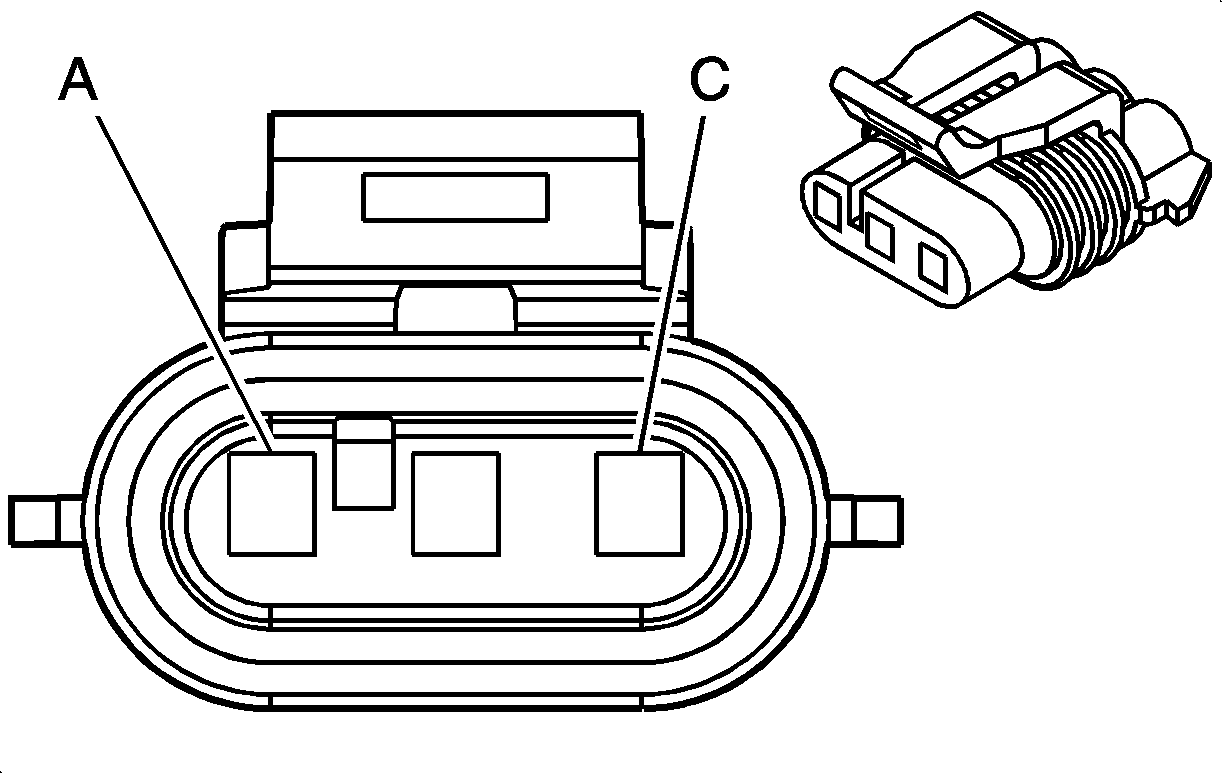
|---|---|---|---|---|---|---|---|
Connector Part Information |
| ||||||
Pin | Wire Color | Circuit No. | Function | ||||
A | OG/BK | 469 | Low Reference | ||||
B | L-GN | 432 | MAP Sensor Signal | ||||
C | GY | 2704 | 5-Volt Reference | ||||
| |||||||
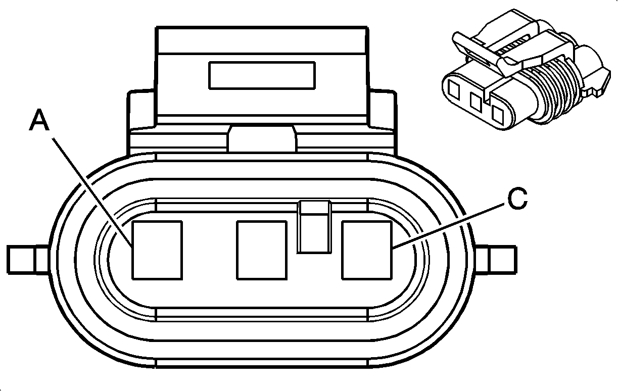
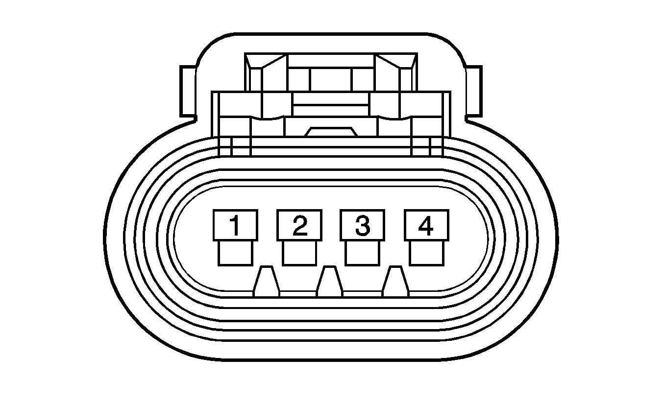
|---|---|---|---|---|---|---|---|
Connector Part Information |
| ||||||
Pin | Wire Color | Circuit No. | Function | ||||
1 | TN | 472 | IAT Sensor Signal | ||||
2 | TN | 2760 | Low Reference | ||||
3 | YE | 492 | MAF Sensor Signal | ||||
4 | OG/WH | 812 | 12-Volt Reference | ||||
| |||||||
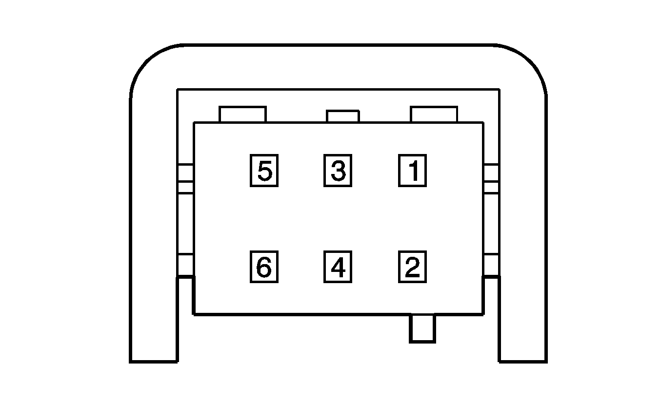
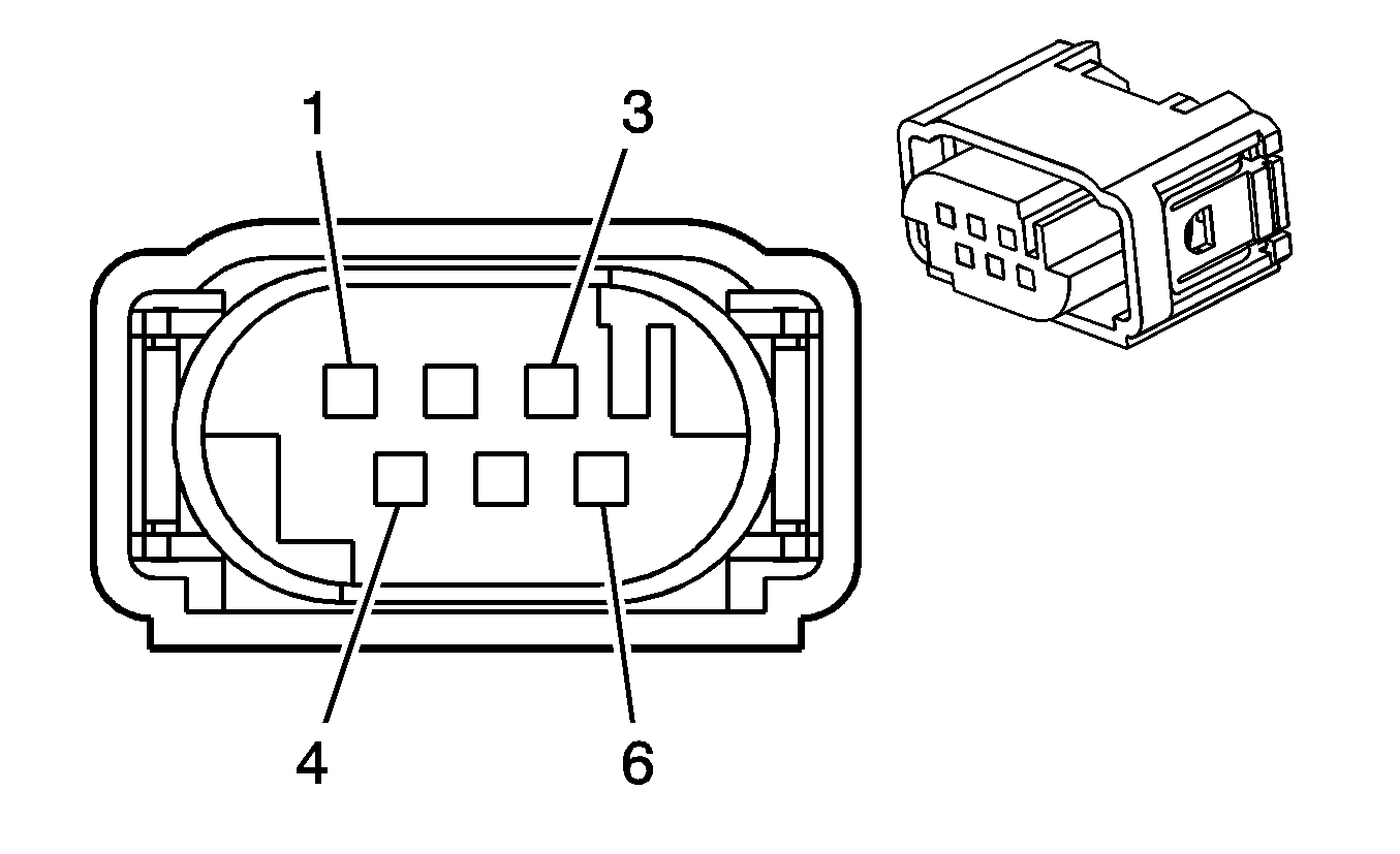
|---|---|---|---|---|---|---|---|
Connector Part Information |
| ||||||
Pin | Wire Color | Circuit No. | Function | ||||
1 | D-GN | 485 | TP Sensor 1 Signal | ||||
2 | PU | 486 | TP Sensor 2 Signal | ||||
3 | GY | 2701 | 5-Volt Reference | ||||
4 | YE | 581 | TAC Motor Control - 1 | ||||
5 | TN | 2752 | Low Reference | ||||
6 | TN | 582 | TAC Motor Control - 2 | ||||
