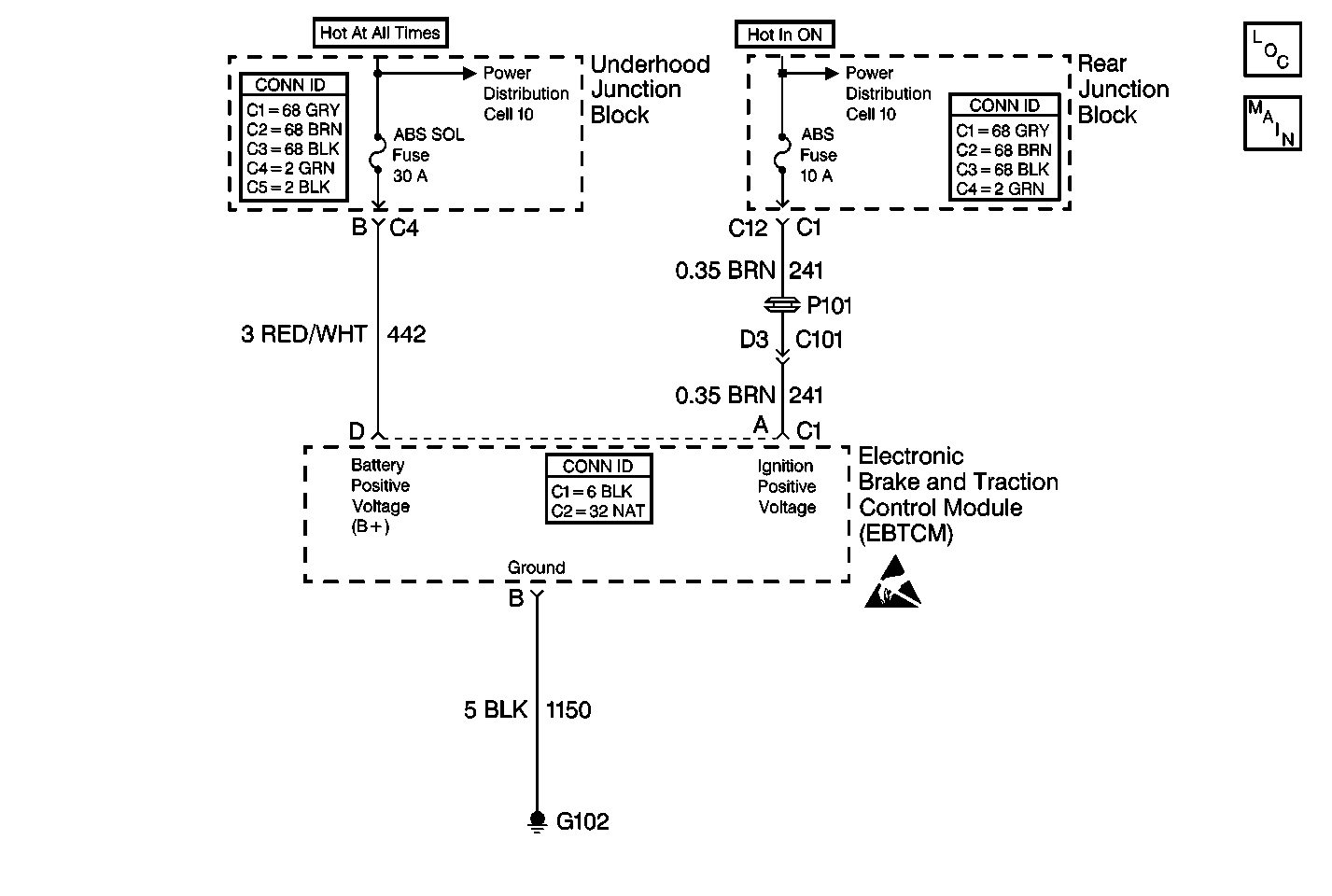
Circuit Description
This circuit is used to monitor the voltage level available to the EBTCM. If the voltage drops below 10.5 volts, full performance of the ABS/TCS/Stabilitrak® is not guaranteed. During ABS/TCS/Stabilitrak® operation, several current requirements will cause a drop in battery voltage. Prior to ABS/TCS/Stabilitrak® operation, the circuit monitors voltage in order to indicate a good charging system condition. The circuit also monitors the voltage during ABS/TCS/Stabiltrak® operation, when the voltage may drop significantly
Conditions for Setting the DTC
All of the following conditions occur:
| • | The vehicle speed is greater than 8 km/h (5 mph). |
| • | The battery positive voltage (B+) is less than 10.5 volts. |
| • | The ignition voltage is less than 10.5 volts. |
Action Taken When the DTC Sets
| • | A malfunction DTC is stored. |
| • | The ABS/TCS/Stabilitrak® is disabled. |
| • | The ABS indicator is turned ON. |
| • | The TRACTION CONTROL indicator is turned ON. |
| • | The DIC displays the SERVICE STABILITY SYS message. |
Conditions for Clearing the DTC
| • | The condition for DTC is no longer present and you used scan tool Clear DTCs function. |
| • | The condition for DTC is no longer present and you used the On-Board Clear DTCs function. |
| • | The EBTCM does not detect the DTC in 50 drive cycles. |
Diagnostic Aids
| • | It is very important that a thorough inspection of the wiring and connectors be performed. Failure to carefully and fully inspect wiring and connectors may result in misdiagnosis, causing part replacement with reappearance of the malfunction. |
| • | An intermittent malfunction can be caused by poor connections, broken insulation, or a wire that is broke inside the insulation. |
| • | If an intermittent malfunction exists refer to Intermittents and Poor Connections Diagnosis in Wiring Systems. |
| • | Check for other low voltage conditions. |
| • | Test the charging system. Refer to Charging System Check in Engine Electrical. |
| • | Possible low voltage condition causes may include: |
| - | charging system malfunction |
| - | excessive battery draw |
| - | weak battery |
| - | faulty system ground |
Test Description
The numbers below refer to step numbers on the diagnostic table.
Step | Action | Value(s) | Yes | No |
|---|---|---|---|---|
1 | Did you perform the Diagnostic System Check? | -- | Go to Step 2 | Go to Diagnostic System Check |
2 | Check the charging system. Refer to Charging System Check in Engine Electrical. Is the charging system OK? | -- | Go to Step 3 | Go to Charging System Check in Engine Electrical |
3 |
Is their evidence of any corrosion or damage? | -- | Go to Step 7 | Go to Step 4 |
Is the resistance less than the specified value? | 2 ohms | Go to Step 5 | Go to Step 8 | |
5 | Measure the voltage between the J 39700 terminals D and B. Is the voltage greater than the specified value? | 10.5 V | Go to Step 6 | Go to Battery Load Test in Engine Electrical |
Is the voltage greater than the specified value? | 10.5 V | Go to Step 9 | Go to Battery Load Test in Engine Electrical | |
7 | Repair as necessary. Refer to Wiring Repairs in Wiring Systems. Did you complete the repair? | -- | Go to Diagnostic System Check | -- |
8 | Repair the open in CKT 1150. Refer to Wiring Repairs in Wiring Systems. Did you complete the repair? | -- | Go to Diagnostic System Check | -- |
9 | Replace the EBTCM. Refer to Electronic Brake Control Module Replacement . Did you complete the repair? | -- | Go to Diagnostic System Check | -- |
