For 1990-2009 cars only
| Figure 1: |
PCM Power and Grounds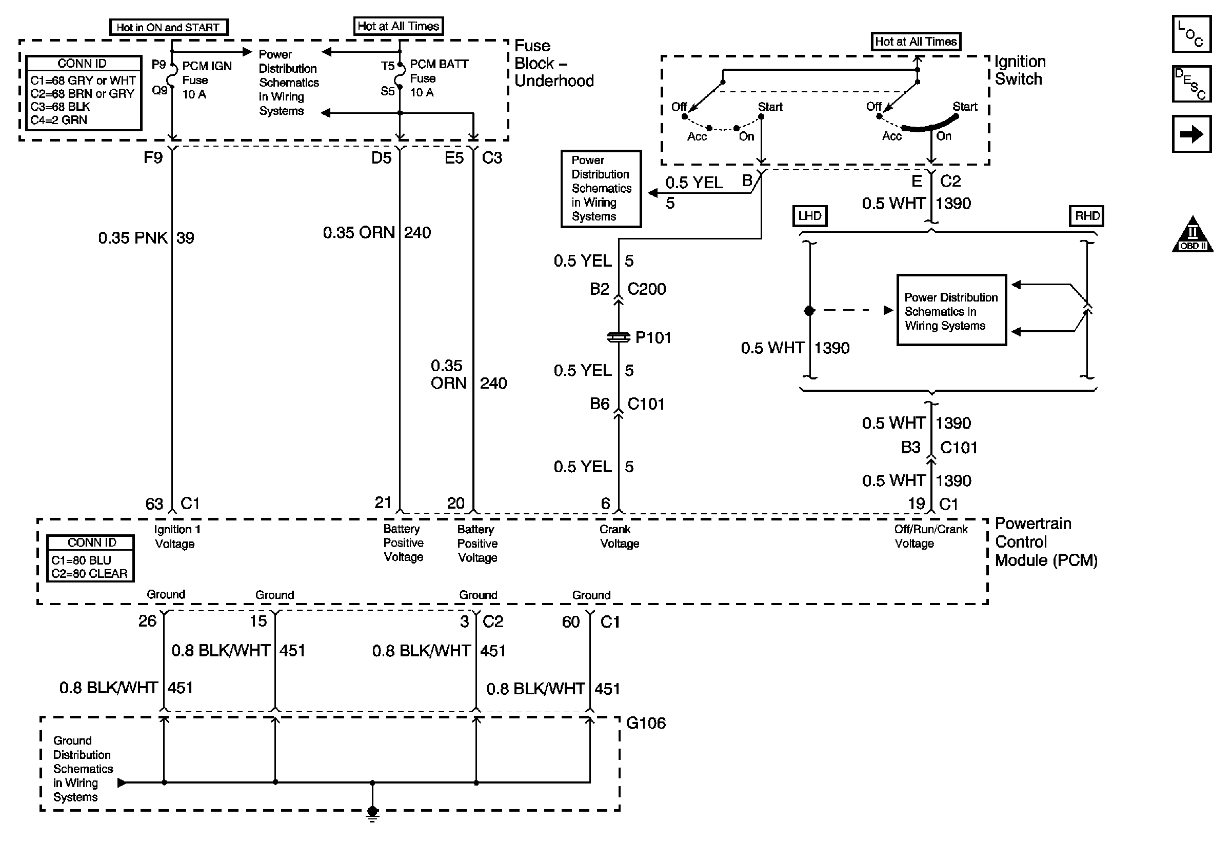
|
| Figure 2: |
Fuel Pump and MIL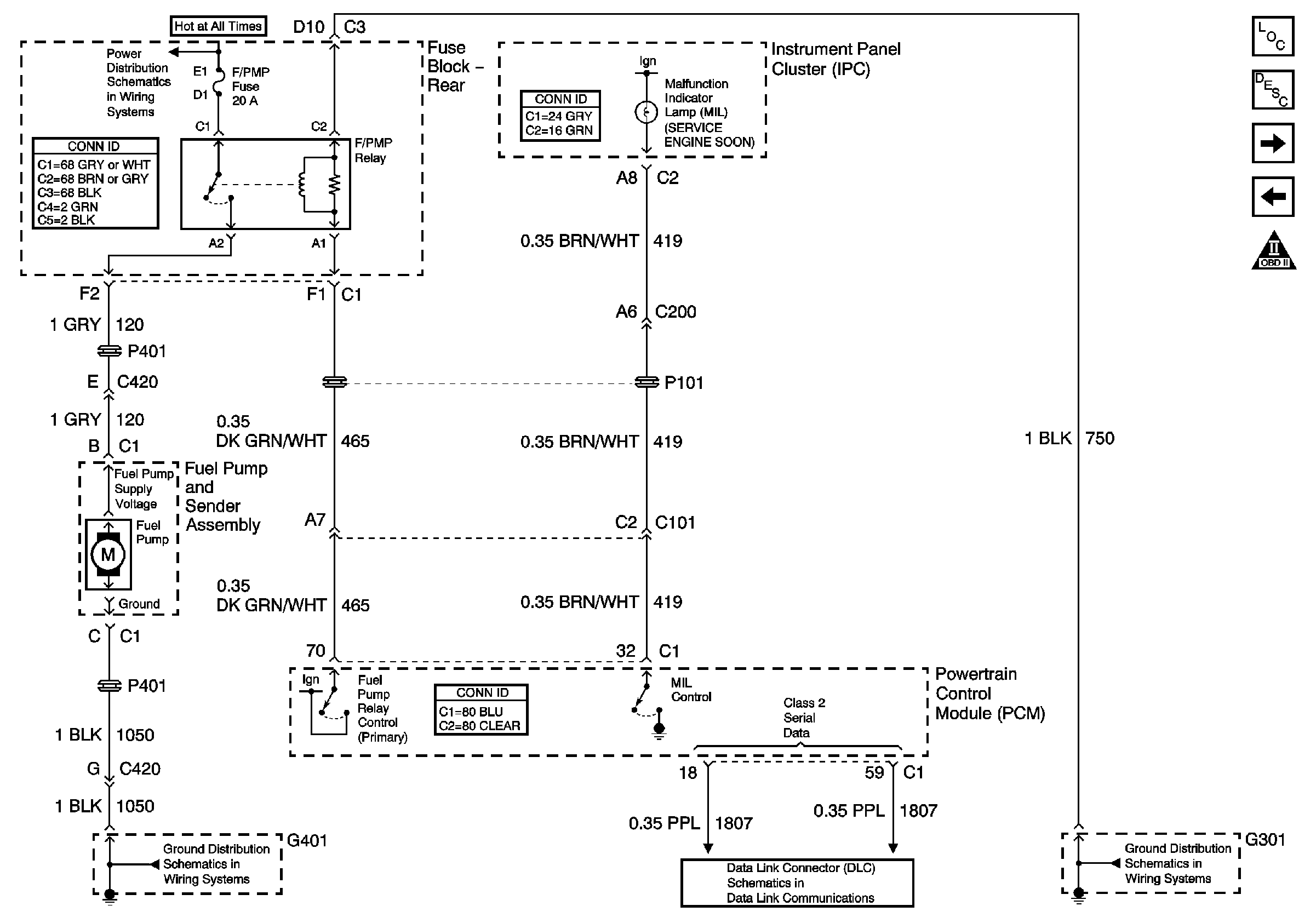
|
| Figure 3: |
Fuel Injectors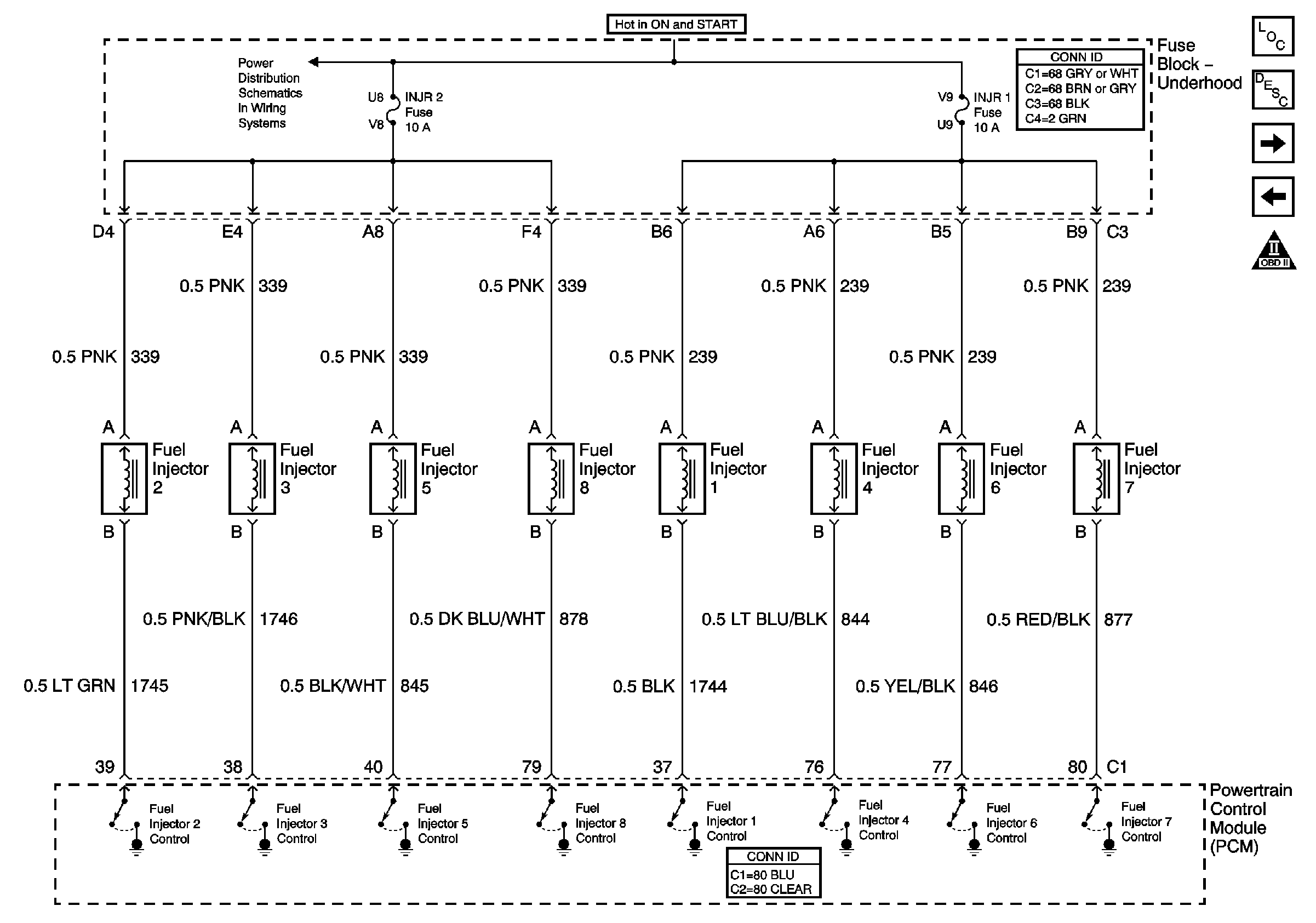
|
| Figure 4: |
Sensor Signals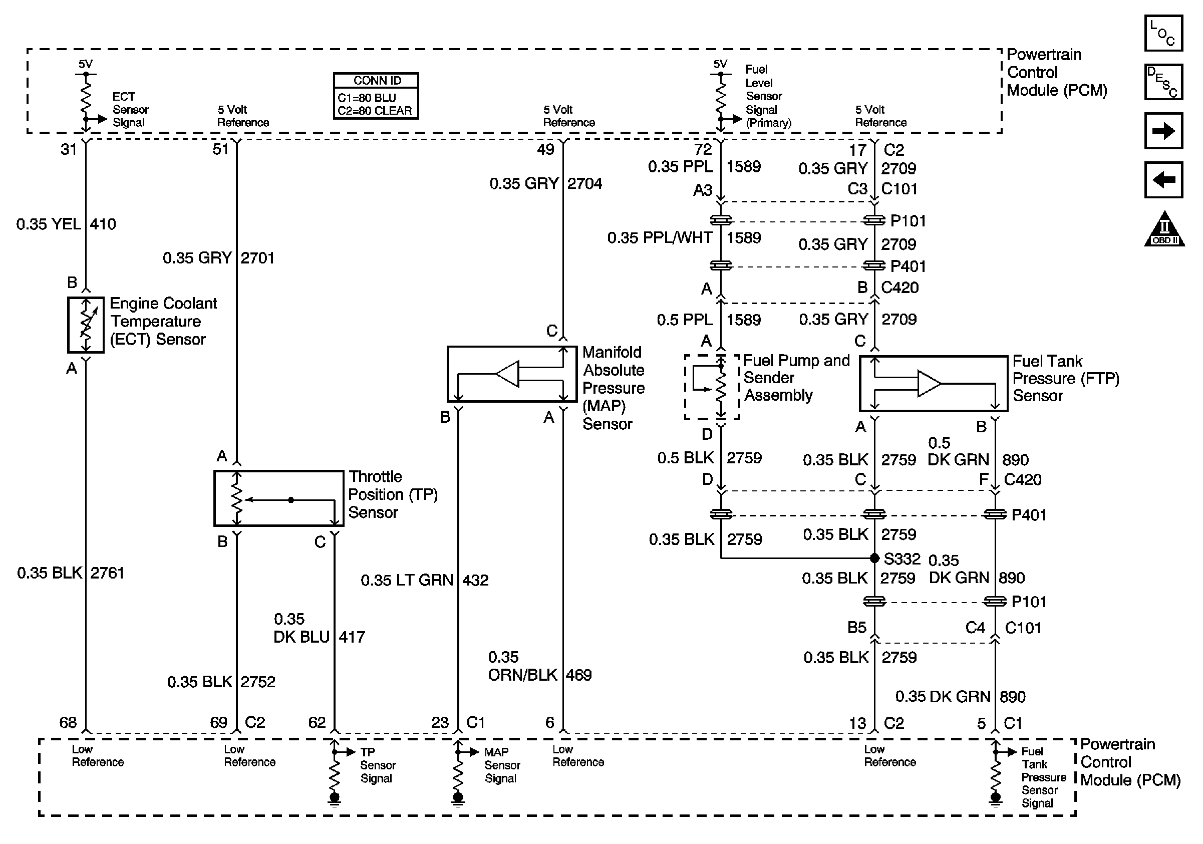
|
| Figure 5: |
Heated Oxygen Sensors (HO2S)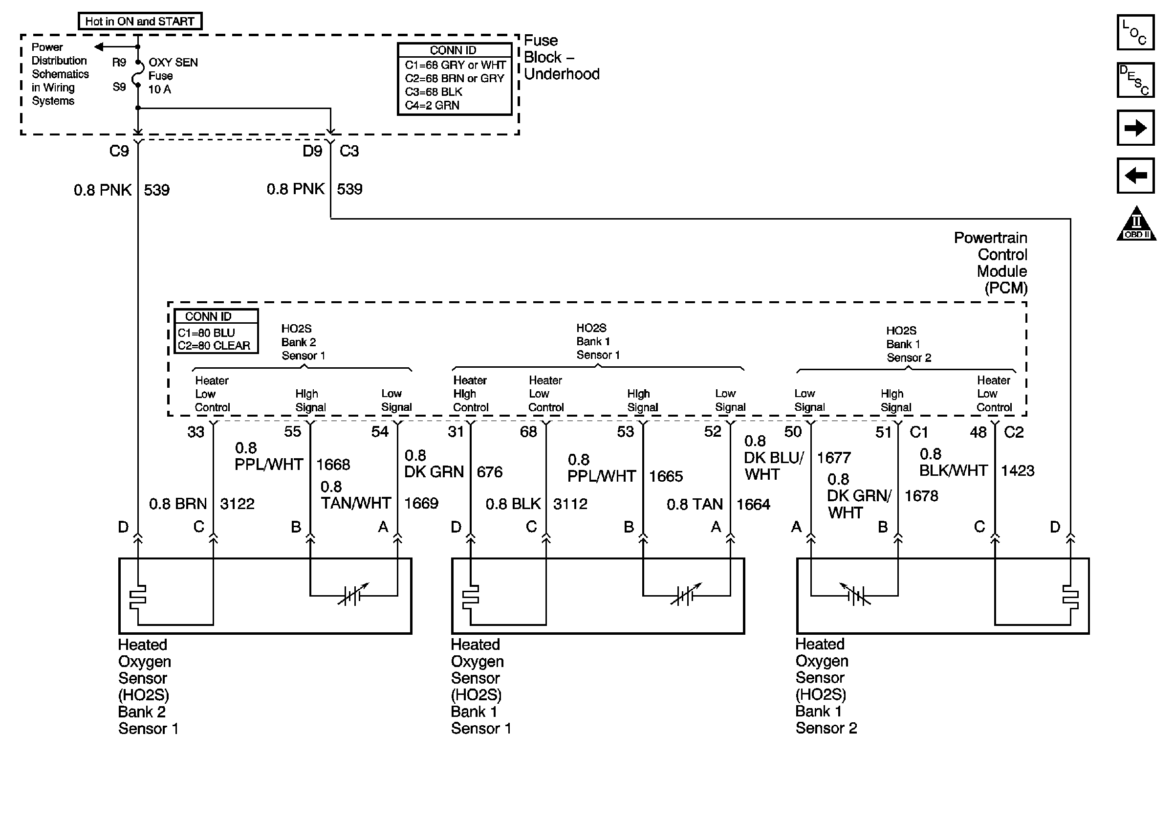
|
| Figure 6: |
EVAP and EGR Signals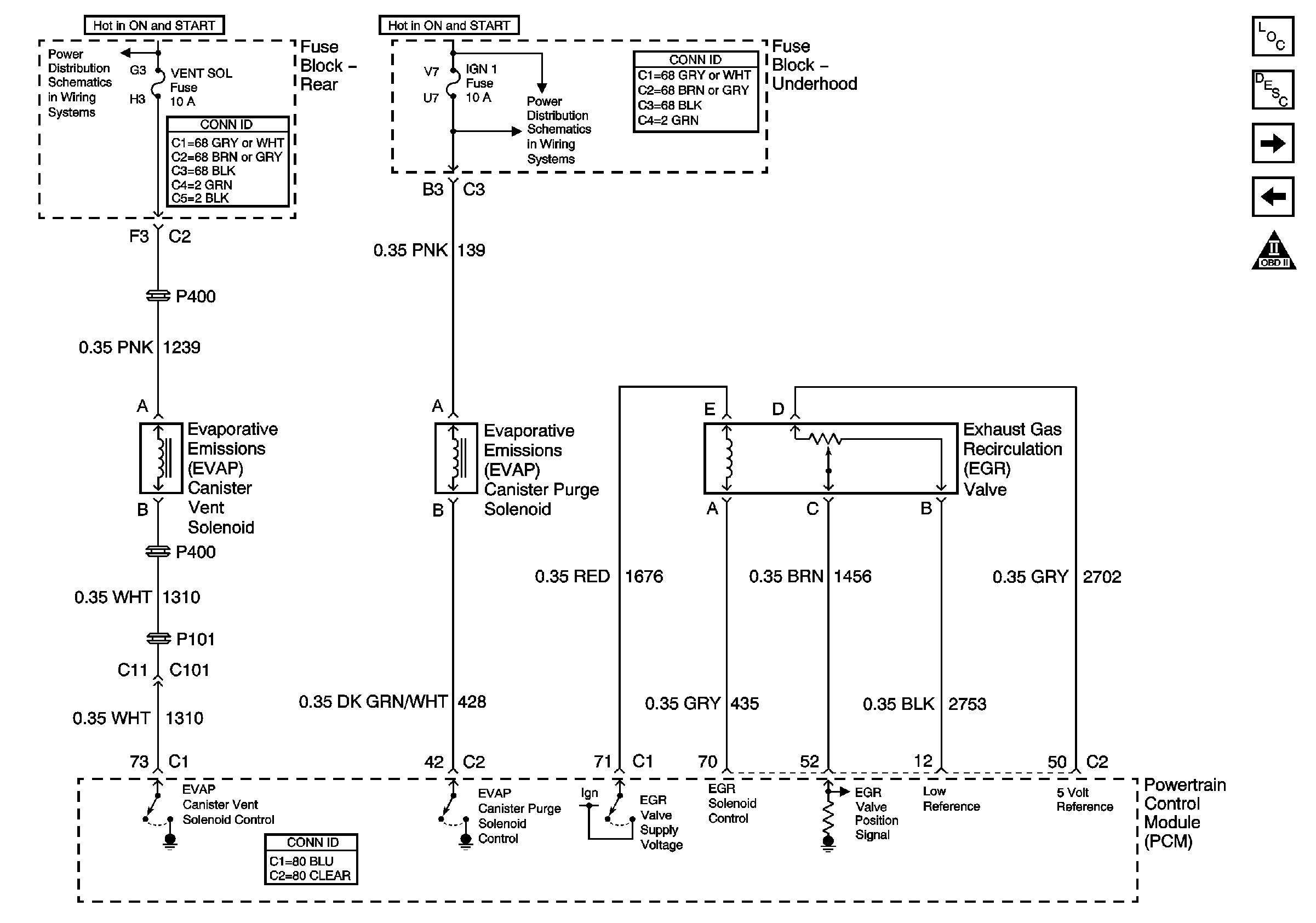
|
| Figure 7: |
MAF and IAC Signals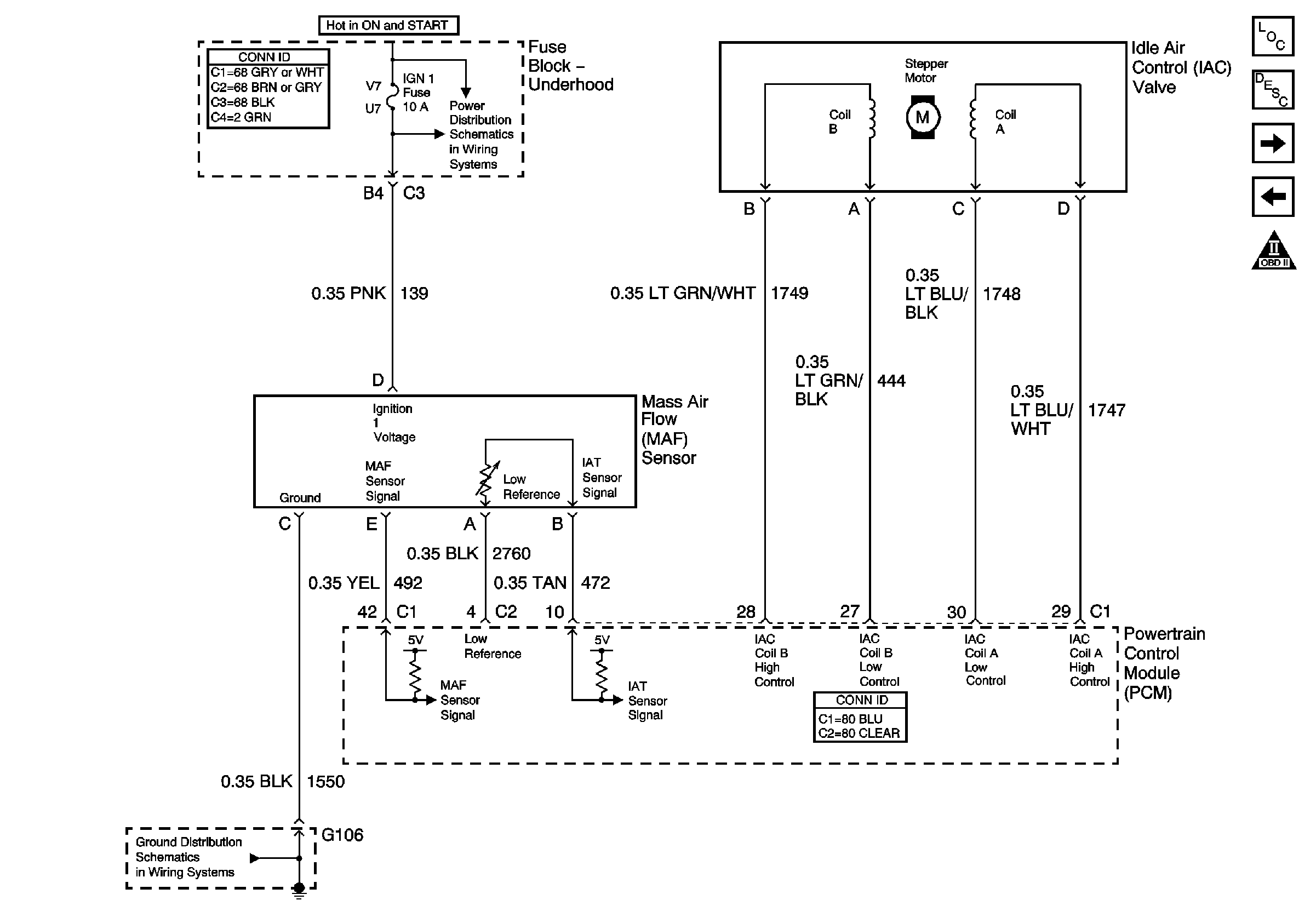
|
| Figure 8: |
PCM Inputs/Outputs (1 of 2)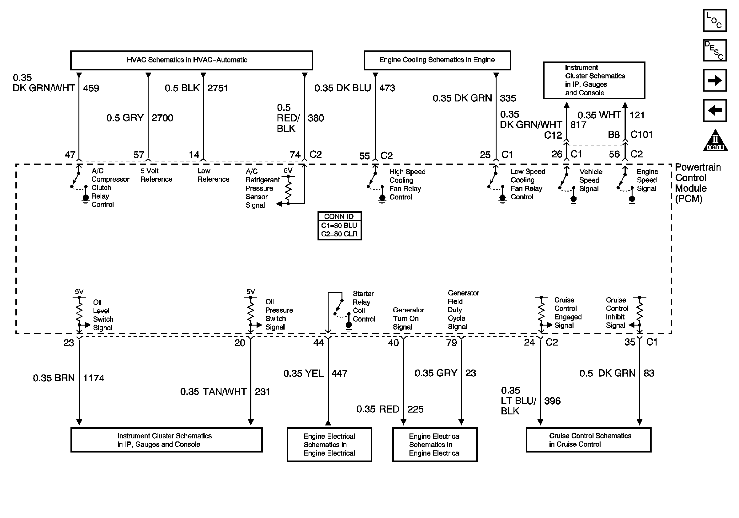
|
| Figure 9: |
PCM Inputs/Outputs (2 of 2)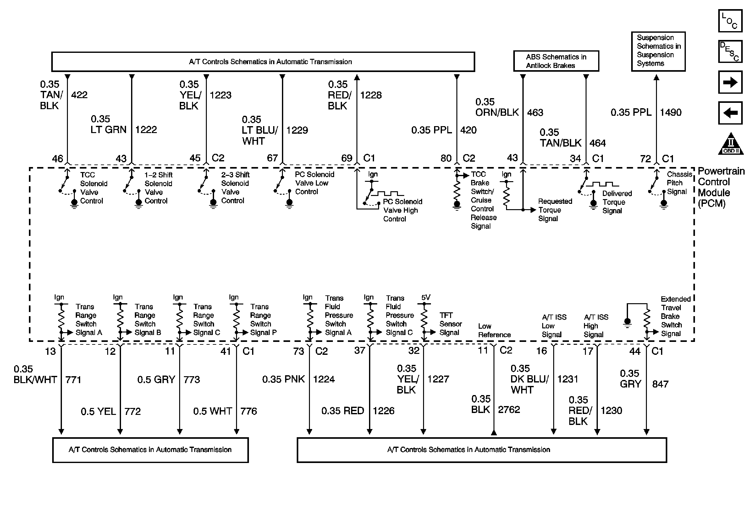
|
| Figure 10: |
Ignition Control Module (ICM) Bank 1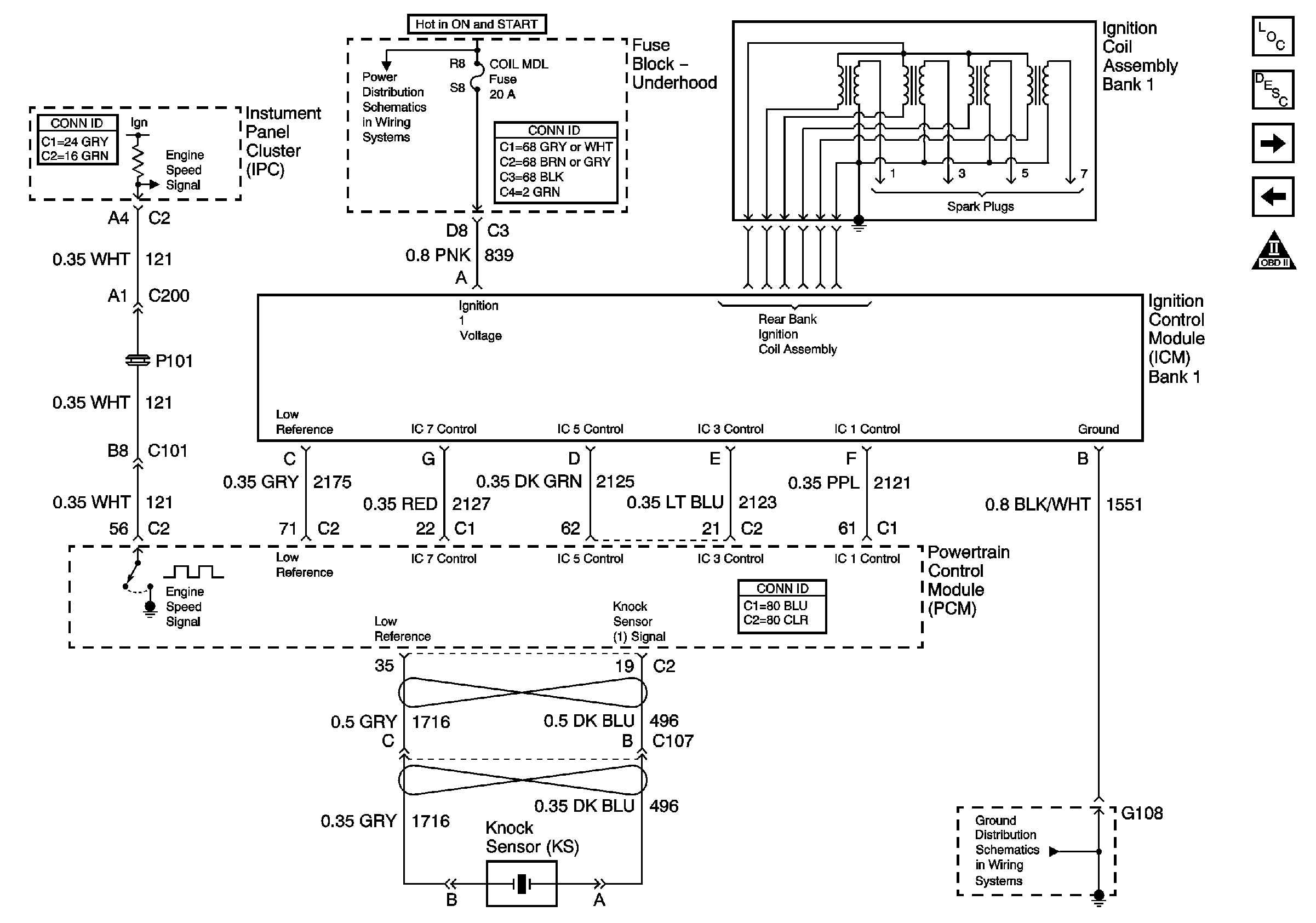
|
| Figure 11: |
Ignition Control Module (ICM) Bank 2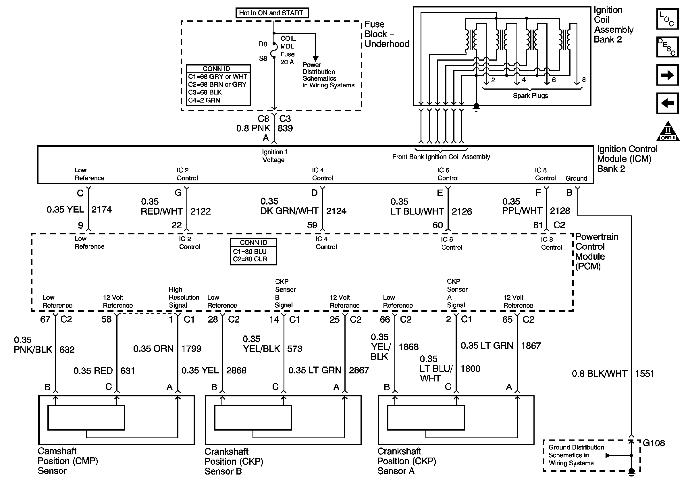
|
| Figure 12: |
Secondary Air Injection (AIR) w/NB6 California Emissions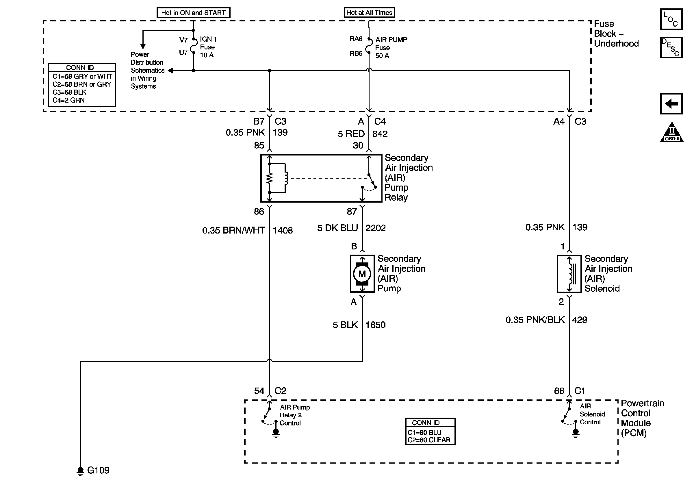
|
