Notice: Refer to Fastener Notice in the Preface section.
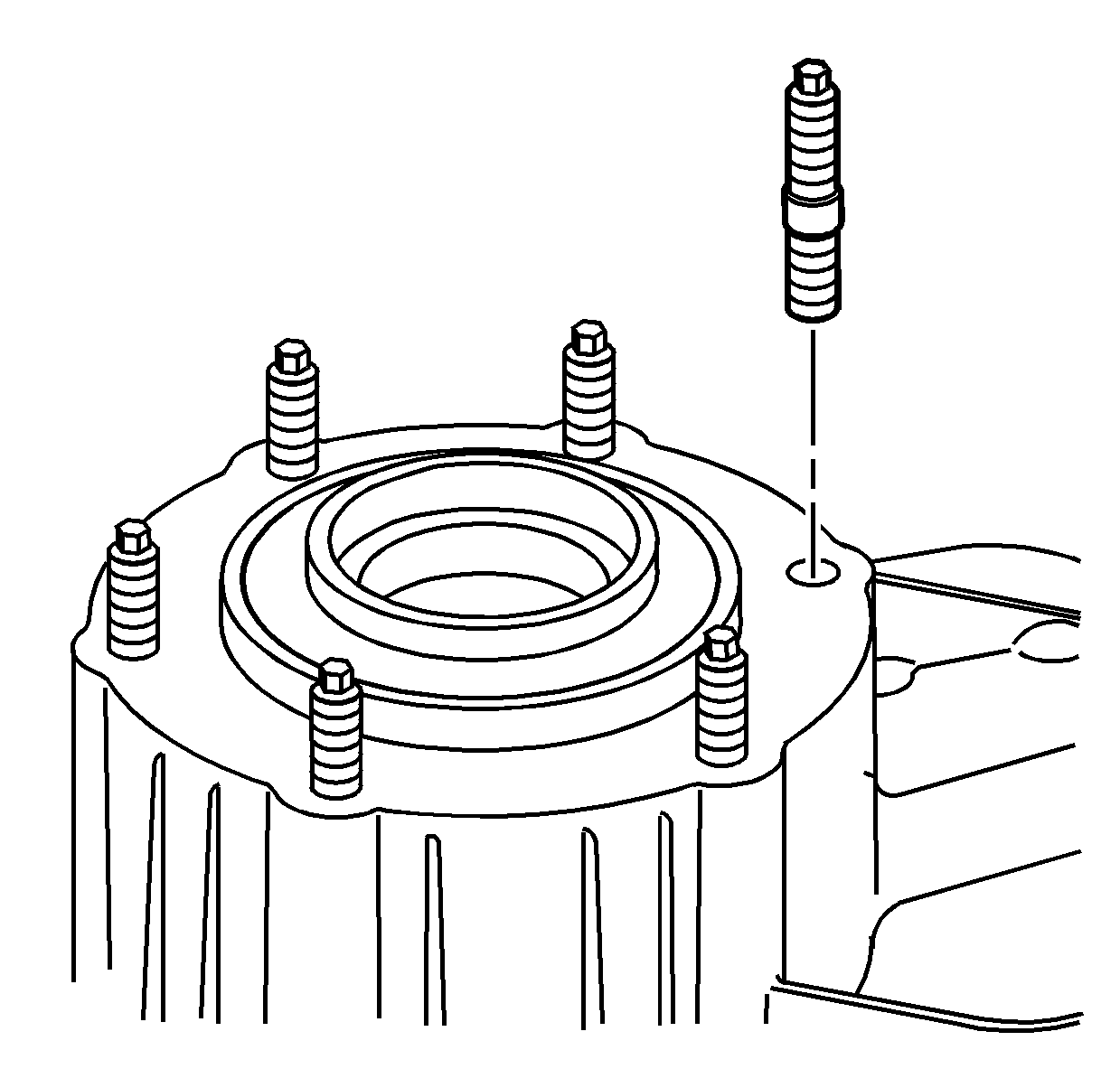
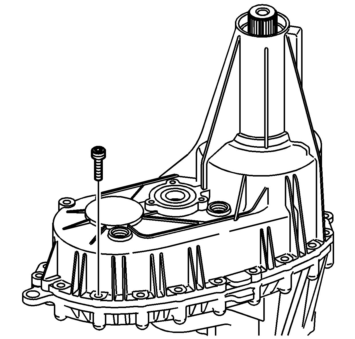
- If removed, install the transfer case mounting studs.
Tighten
Tighten the mounting studs to 31 N·m (23 lb ft).
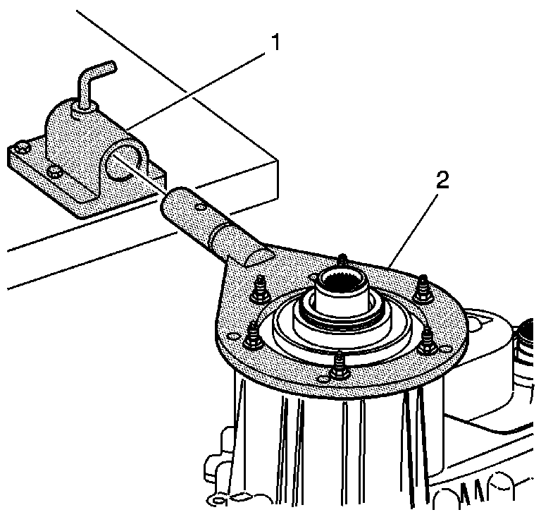
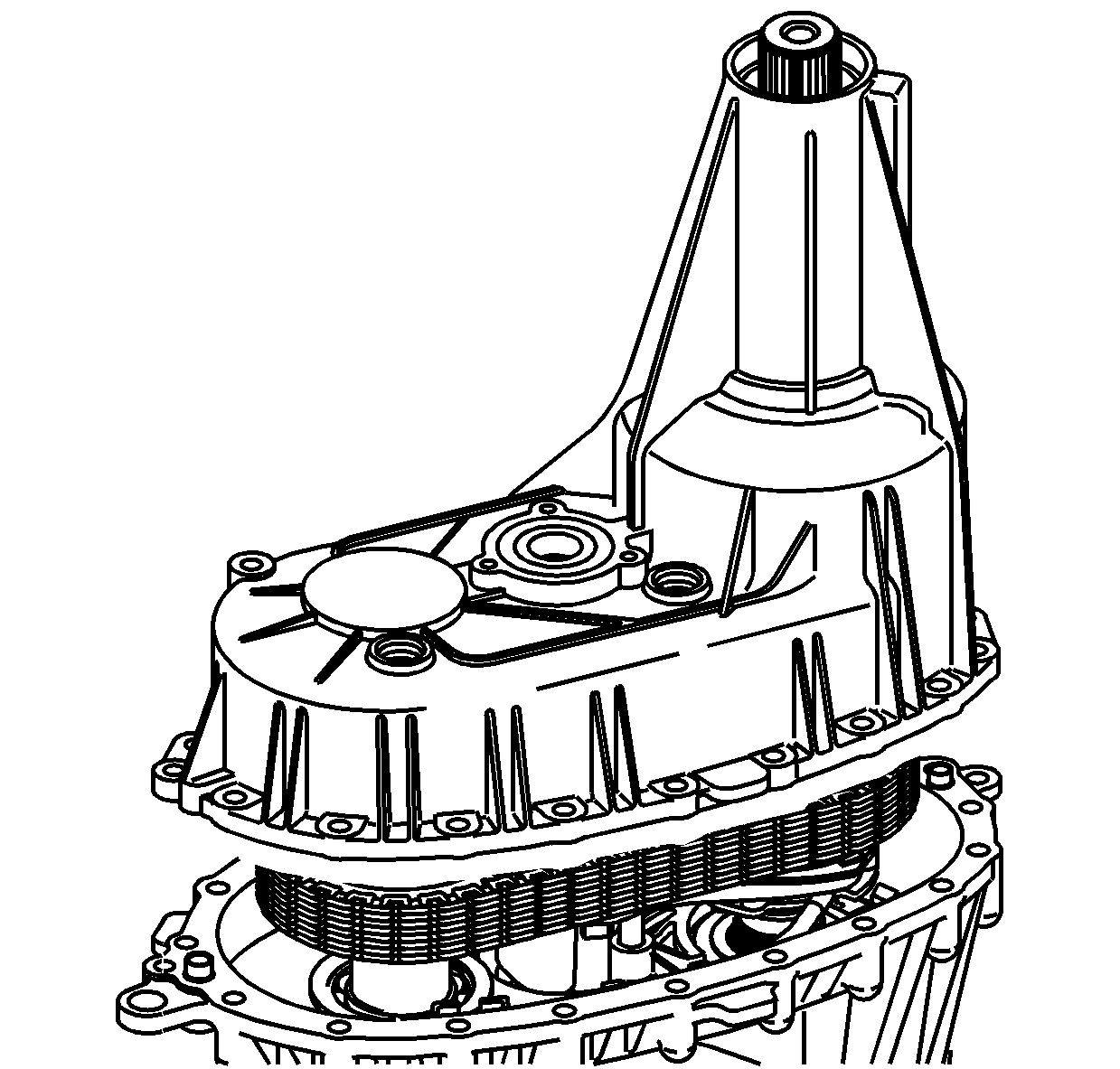
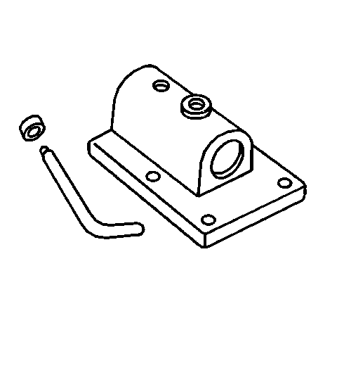
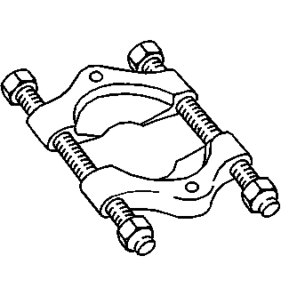
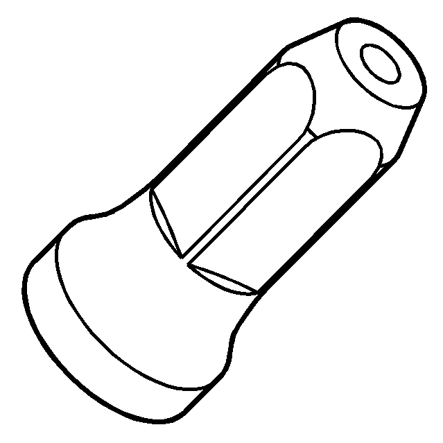
- Attach the J 45759
to the front transfer case using the
adapter studs. All of the assembly procedures can be performed with the
case mounted to the J 45759
.
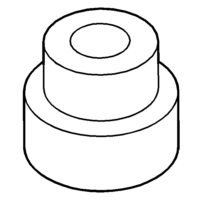
- Install the J 45759
(2) into the J 3289-20
(1) and secure with the pivot pin.
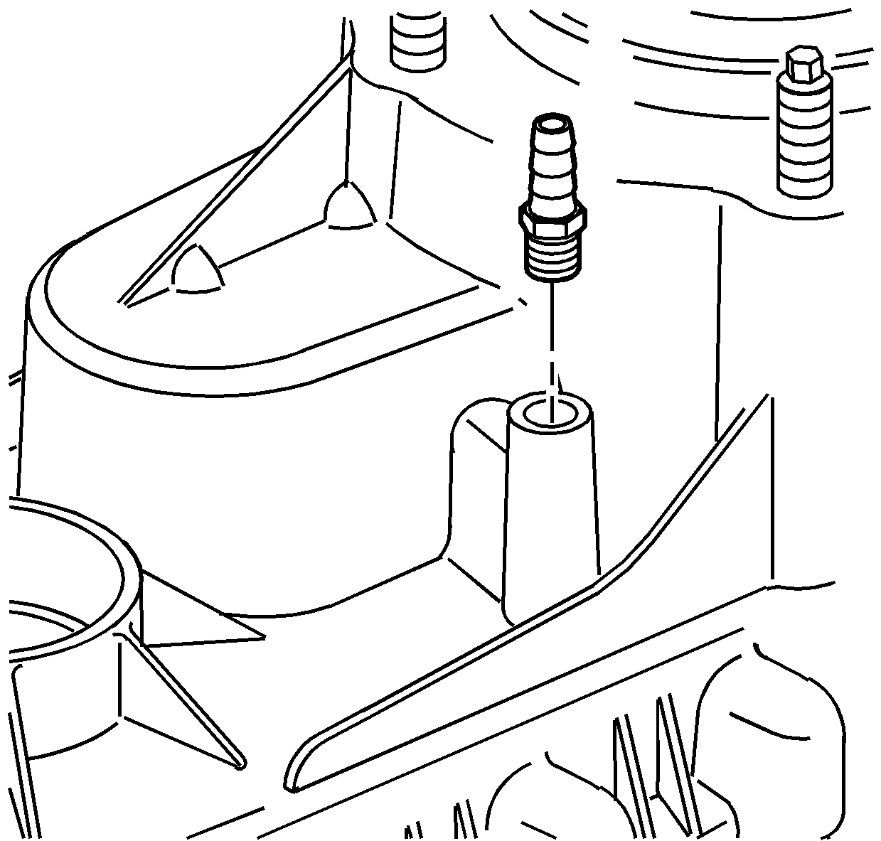
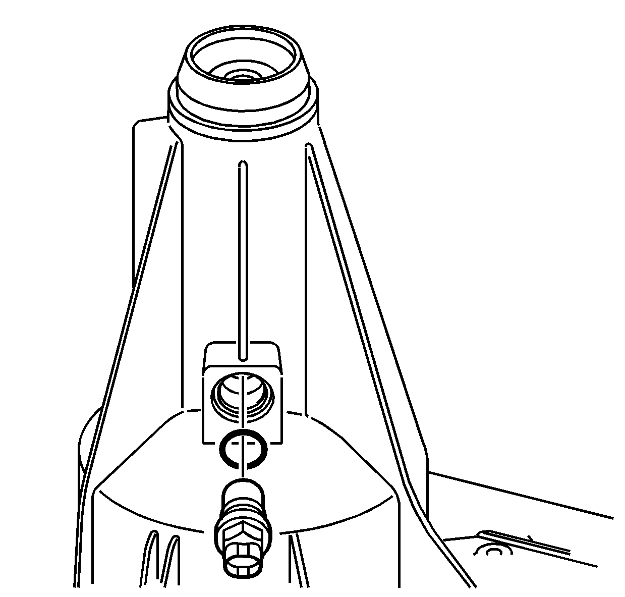
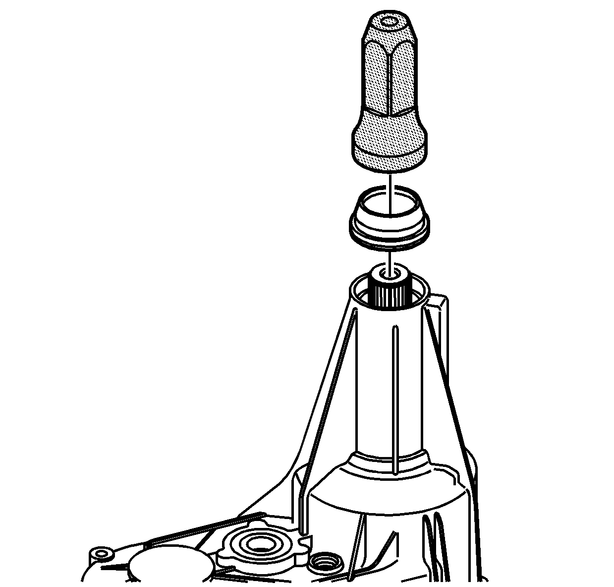
- If the vent is removed,
apply pipe sealant GM P/N 12346004 (Canadian P/N 10953480)
to the threads on the vent.
- Install the vent.
Tighten
Tighten the vent to 6 N·m (53 lb in).
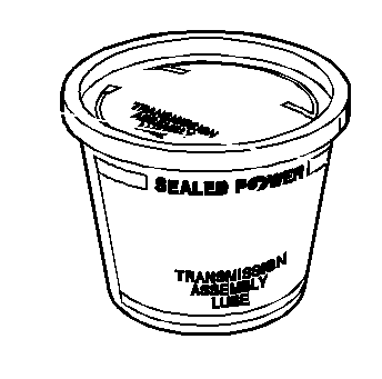
Important: Lubricate all of the bearings and bearing journals with transfer case
fluid during installation.
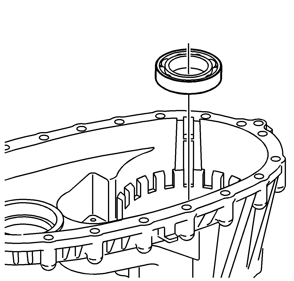
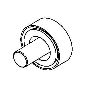
- Install the input shaft bearing in the front case half.
| • | Use a hammer and a brass drift only on the outer bearing race. |
| • | Ensure the bearing is kept square to the bore while installing. |
- Install the front bearing,
for the front output shaft, in the front case half.
| • | Use a hammer and a brass drift only on the outer bearing race. |
| • | Ensure the bearing is kept square to the bore while installing. |
- If it is a new shaft or
if the cup plug was removed, install the cup plug in the front output shaft,
using a suitable driver. Install the cup plug 1 mm (0.039 in)
from flush with the end of the shaft.
- Install the front output
shaft assembly.
Important: There was a mid year production change in the design to the input shaft
and the drive sprocket. If the input shaft or the drive sprocket is found
faulty during inspection, it may require the replacement of both components.
If the drive sprocket and the input shaft are the older designs and either
component requires replacement, both the input shaft and drive sprocket must
be replaced as a kit. The replacement components will only be the new design.
If the input shaft and the drive sprocket are the new design, the components
can be replaced individually. Assembling an old design with a new design component
will cause a drivability concern.
- Inspect the input shaft to ensure if it is the old design or new design.
Measure the distance from the drive sprocket shoulder (A) to the end
of the splines for the planetary carrier (B). The measurement for the
old design input shaft is 84.51-84.71 mm (3.327-3.335 in).
The measurement for the new design input shaft is 85.32-85.52 mm
(3.359-3.367 in).
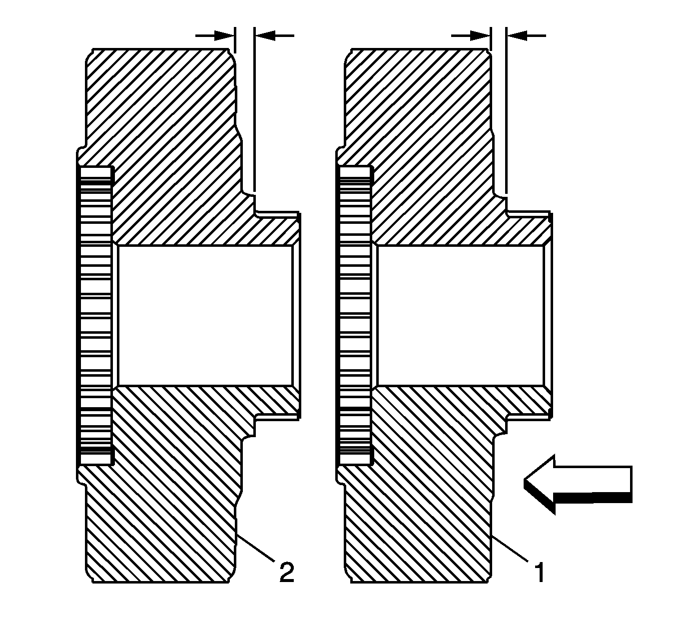
- Inspect the drive sprocket to identify
if it is the older design (1) or the newer design (2).
There is only a slight difference to the drive sprocket on the rear
surface. If the rear of the sprocket is almost flat, it is the old design (1).
If the rear of the sprocket has a slight step of approximately 1 mm
(0.039 in), it is the new design (2).
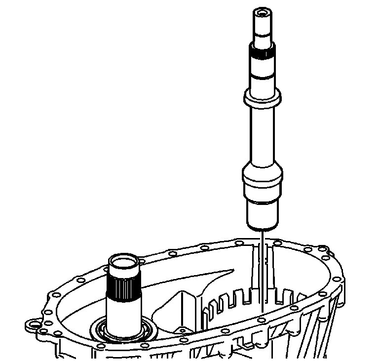
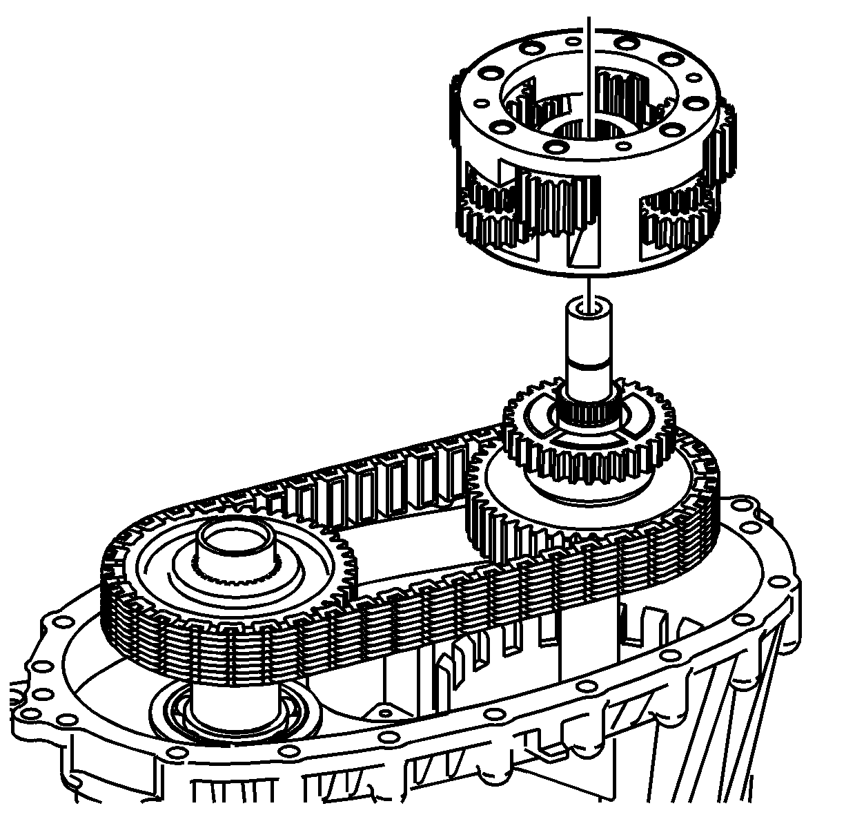
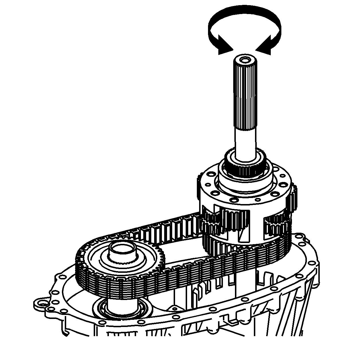
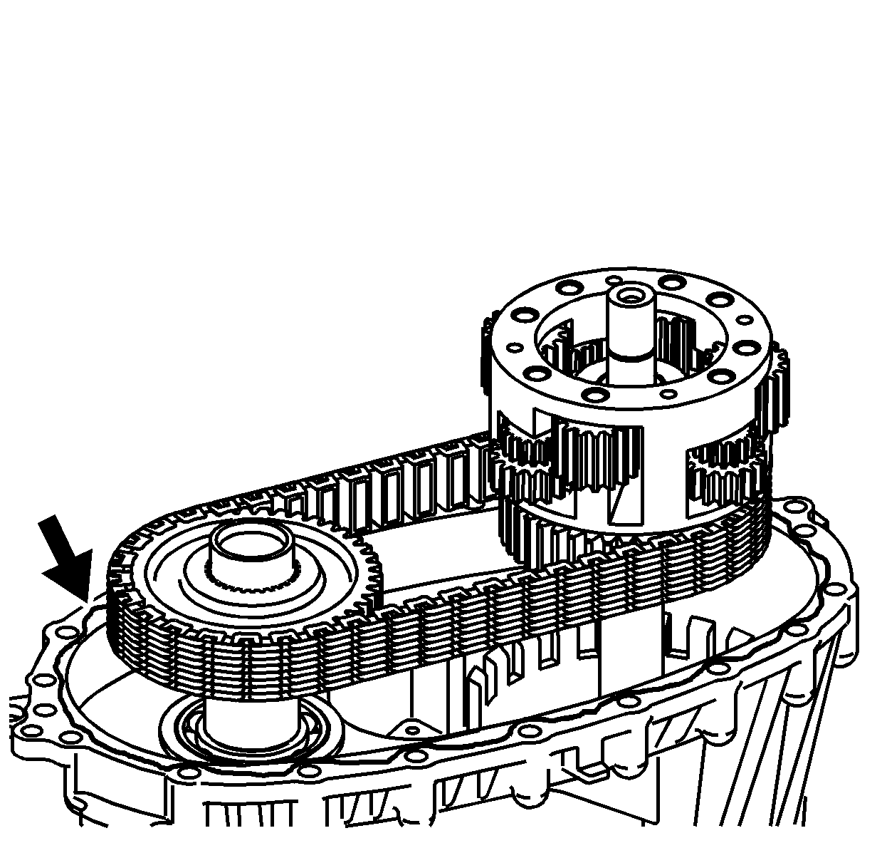
- Install the input shaft.
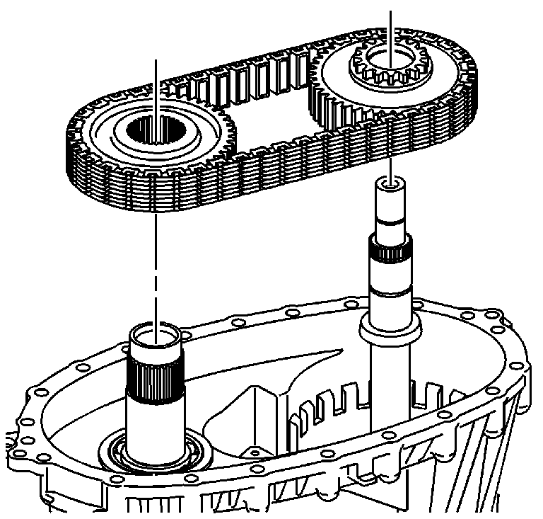
Important: If using the chain and sprockets again, ensure to align the marks of
the drive chain and sprockets.
- Install the drive chain and sprockets. The blue link on the chain faces
up.
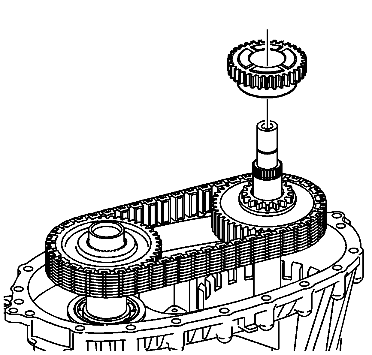
- Install the front sun
gear.
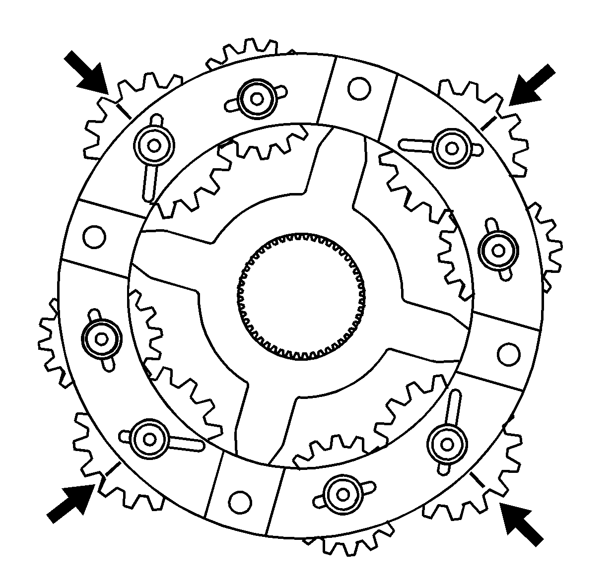
Important: The planetary differential gears are timed to the sun gears. If the
gears are not timed properly, the differential will not rotate without binding.
- With the rear side of the planetary differential facing up, align the
marks on the pinion gears. Position the alignment marks with an area on the
planetary housing that can be reference for all gears.
- Install the planetary
differential assembly.
| • | Do not rotate the planetary differential pinion gears when installing. |
| • | Ensure the alignment marks are still in position. |
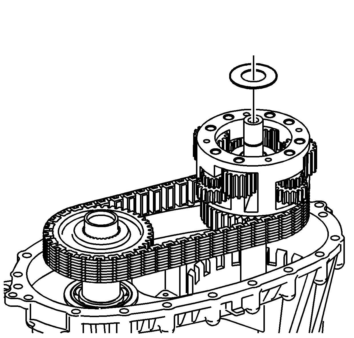
- Lubricate the sun gear
thrust washer with J 36850
or equivalent.
- Install the sun gear thrust washer.
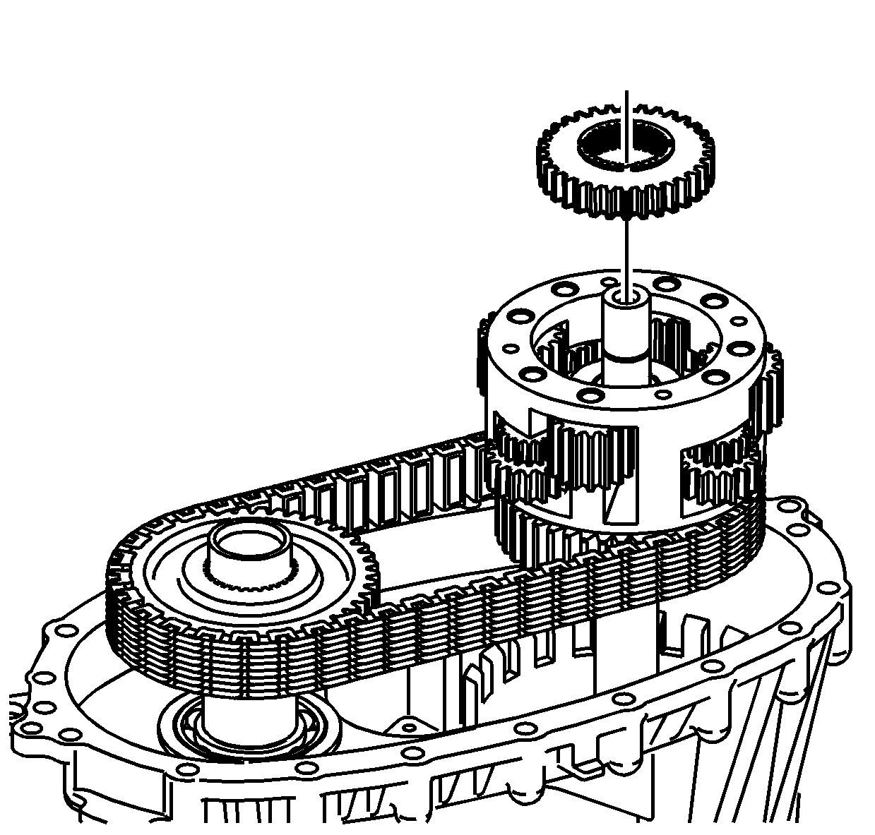
- Install the rear sun gear.
| • | The shoulder side of the gear faces up. |
| • | Do not rotate the planetary pinion gears. |
- Temporarily install the
rear output shaft to the planetary differential and the rear sun gear.
- Rotate the rear output shaft three or four revolutions to rotate
the planetary differential pinion gears. If properly aligned, the planetary
pinion gears will rotate freely, and there will be no binding.
- Remove the rear output shaft without disturbing the rear sun
gear.
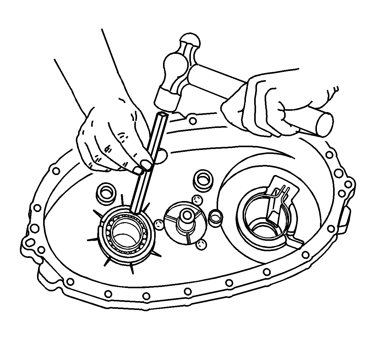
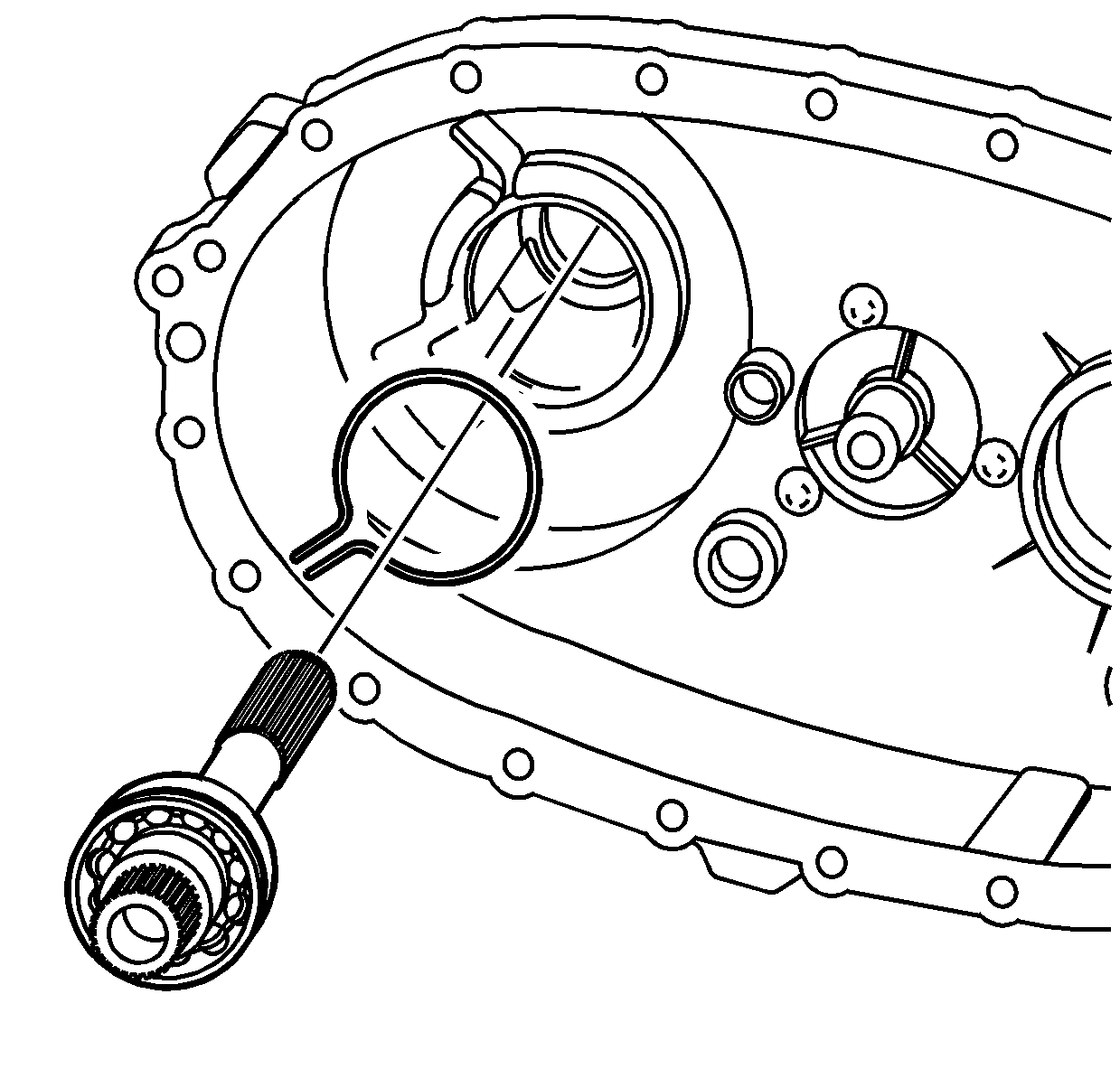
- Install the front output
shaft rear bearing in the rear case half.
| • | Use a hammer and a brass drift only on the outer bearing race. |
| • | Ensure the bearing is kept square to the bore while installing. |
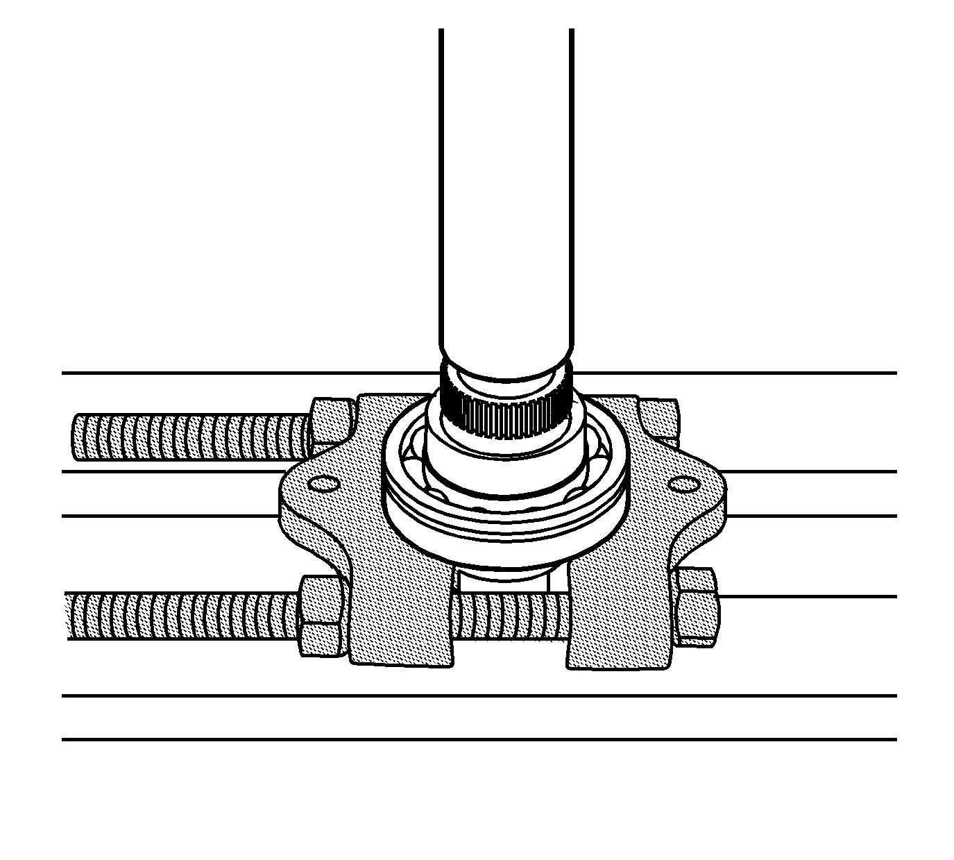
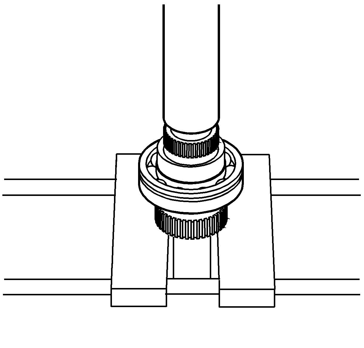
- Using a hydraulic press
and the J 22912-B
, install
the rear output shaft bearing.
| • | The retaining ring groove on the bearing goes toward the input
end or forward. |
| • | Use a suitable press plate on the end of the rear output shaft. |
| • | Ensure the bearing is supported on the inner race. |
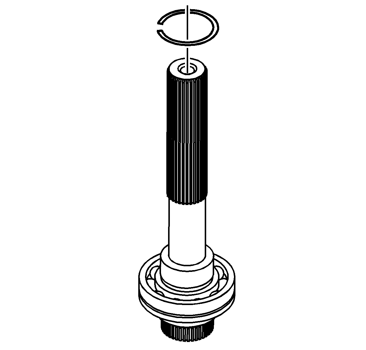
- Install a NEW retaining
ring for the rear output shaft bearing.
- Using a hydraulic press,
install a NEW speed reluctor wheel.
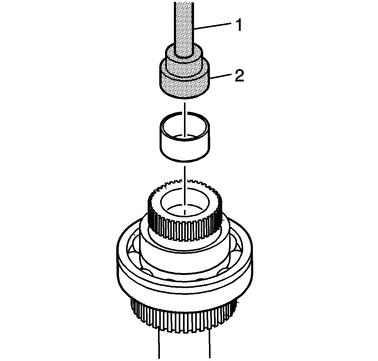
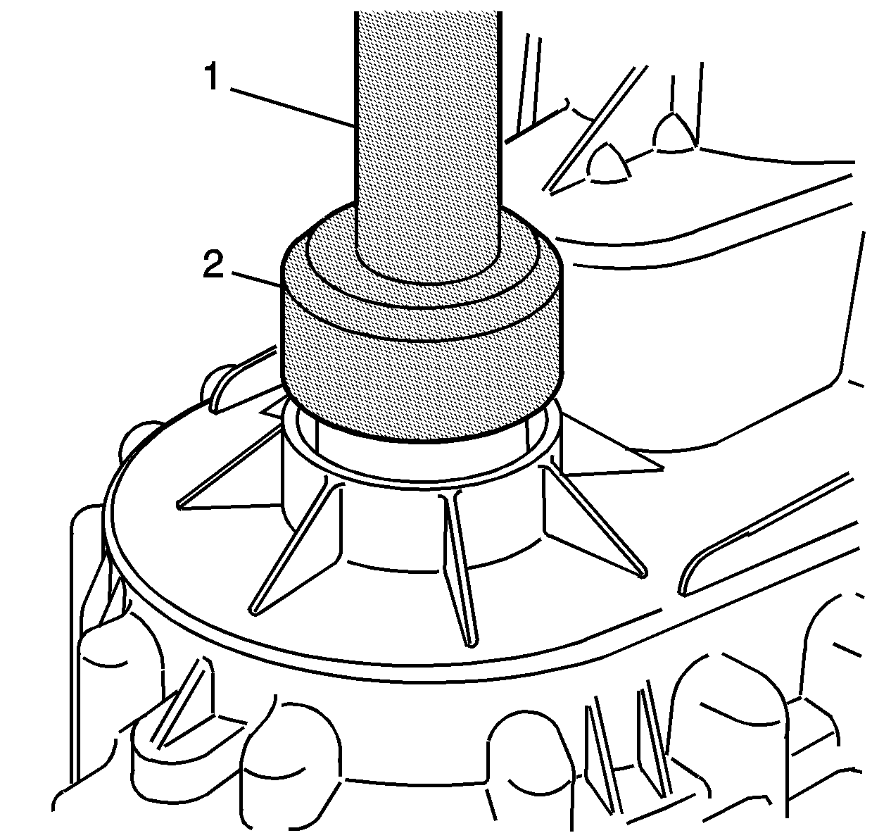
- Using J 42176
(1) and J 45757
(2), install the input shaft
rear support bushing in the rear output shaft.
- Install the rear output
shaft in the rear case half.
| 28.1. | Spread the rear output shaft rear bearing outer retaining ring. |
| 28.2. | Install, until the rear output shaft bearing outer retaining ring
is seated in the bearing groove. |
Important:
| • | Ensure that both the sealing surfaces on the front and rear case halves
are free of dirt, oil, and cleaning solvent. |
| • | Ensure the locating pins are installed in the case halves. |
- Install the locating pins in the front case and rear case half, if necessary.
- Apply a 3.175 mm (1/8 in) bead of RTV sealant GM P/N 12345739
(Canadian P/N 10953541) or equivalent to the mating surfaces
of the front case half.
- Lower the rear case half
into place.
The rear output may require rotating to align the
teeth with the planetary carrier.
Notice: This component is made of magnesium. Proper assembly is required to
prevent damage. Ensure the magnesium transfer case housings are properly
insulated from all external steel components, or galvanic corrosion will occur.
New nylon coated case bolts and aluminum washers must be used. Use only aluminum
fill and drain plugs. Use only aluminum brackets under the case bolts. Ensure
new seals are installed that have a rubber insulated outside diameter and
have no tears or cuts. Extensive damage will occur if there is galvanic corrosion
between the magnesium and steel components.
- Inspect the nylon coating on the case bolts for cuts or
tears.
- Replace the case bolts if there is any damage to the nylon coating.
Important: The case bolts are self-tapping; they must be hand started. Do
not use power assisted tools to install the bolts.
- Install the case bolts, the washers, and the brackets.
Tighten
Tighten the case bolts to 21 N·m (15 lb ft).
- Install the vehicle speed
sensor with a new O-ring seal.
Tighten
Tighten the speed sensor to 17 N·m (13 lb ft).
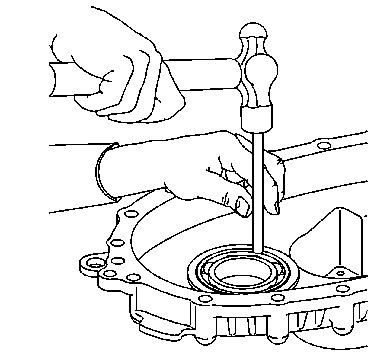
- Using J 45756
, install the rear output shaft seal.
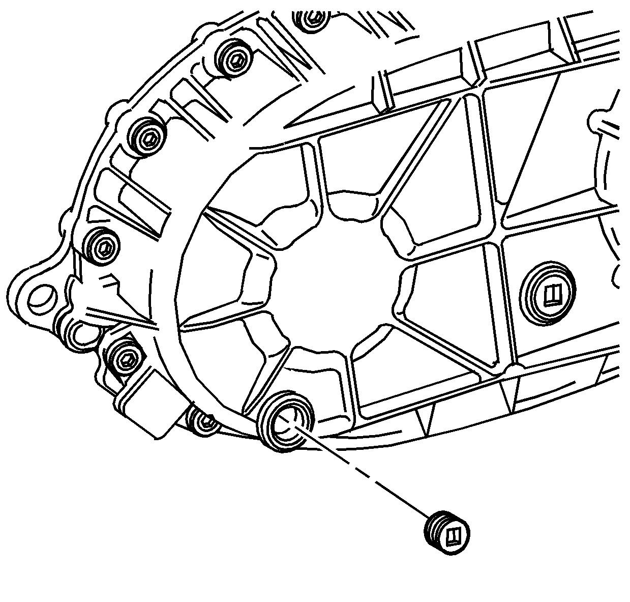
- Apply pipe sealant GM P/N 12346004
(Canadian P/N 10953480) to the threads on the drain plug and
fill plug.
- Install the drain plug and the fill plug.
Tighten
Tighten the drain plug and fill plug to 25 N·m (18 lb ft).
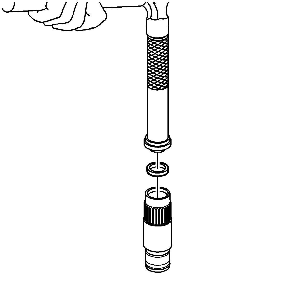
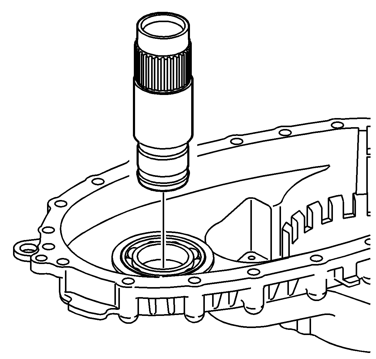
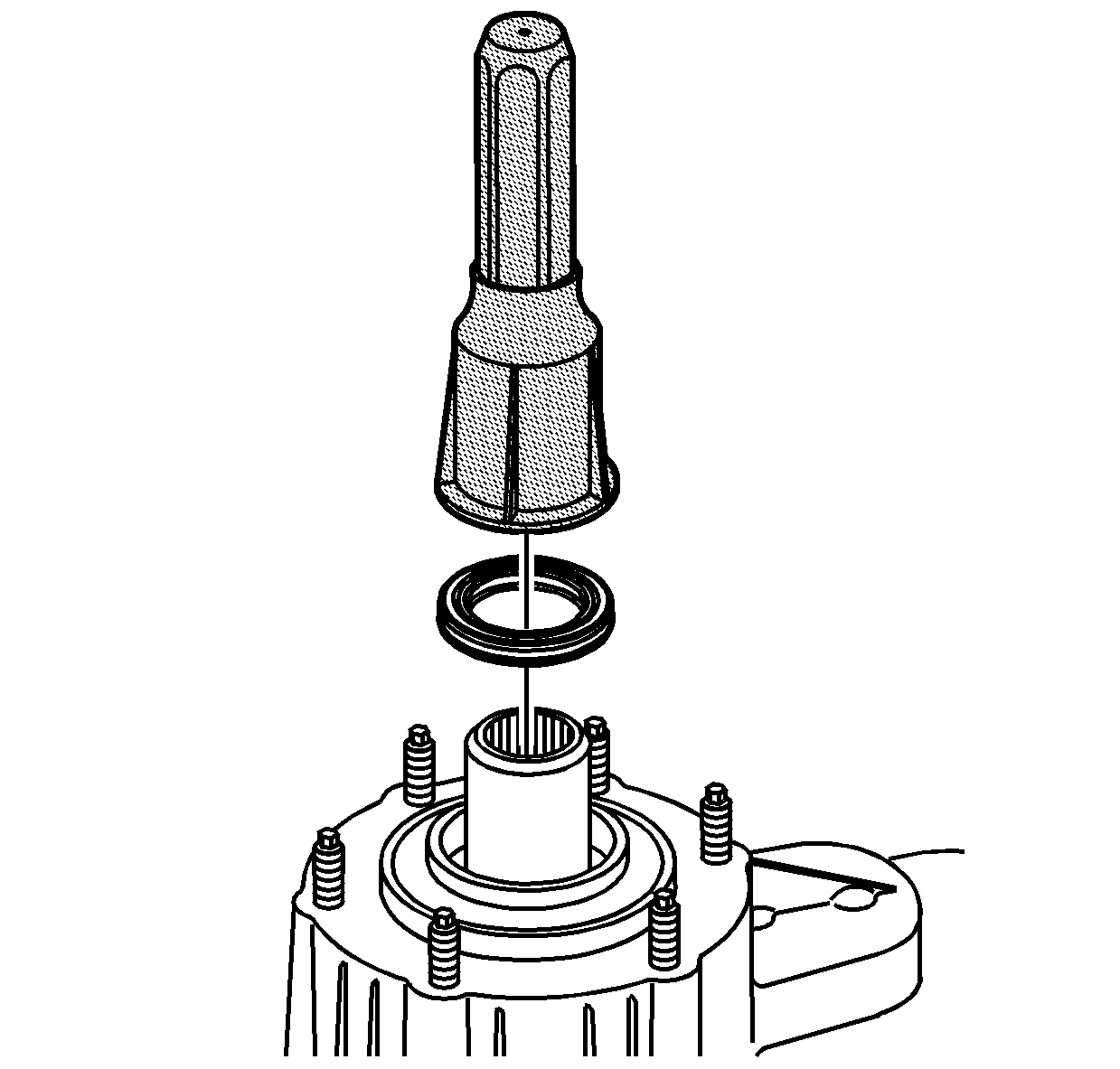
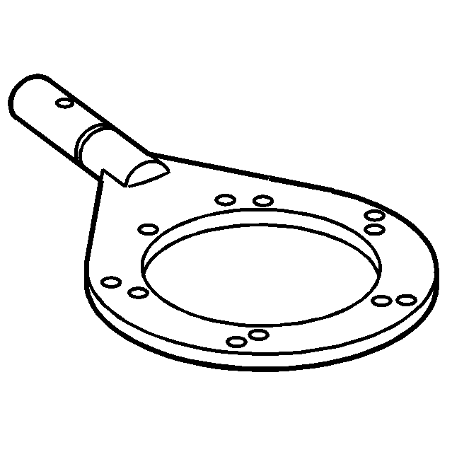
- Using the J 43484
(2) and the J 8092
(1), install the front output
shaft seal.
- Using the J 42738
, install the front input shaft seal.
- Remove the transfer case from the J 45759
.
