For 1990-2009 cars only
Special Tools
EN-46105 Camshaft Locking Tool
Removal Procedure
- Remove the bank 2 cylinder head cover. Refer to Camshaft Cover Replacement - Left Side.
- Remove the bank 2 cylinder head camshaft position actuators. Refer to Camshaft Position Actuator Replacement - Bank 2 (Left Side) Exhaust and Camshaft Position Actuator Replacement - Bank 2 (Left Side) Intake.
- Remove EN-46105 tool (1) from the bank 2 camshafts.
- Observe the markings (1) on the bearing caps. Each bearing cap is marked in order to identify its location. The markings have the following meanings:
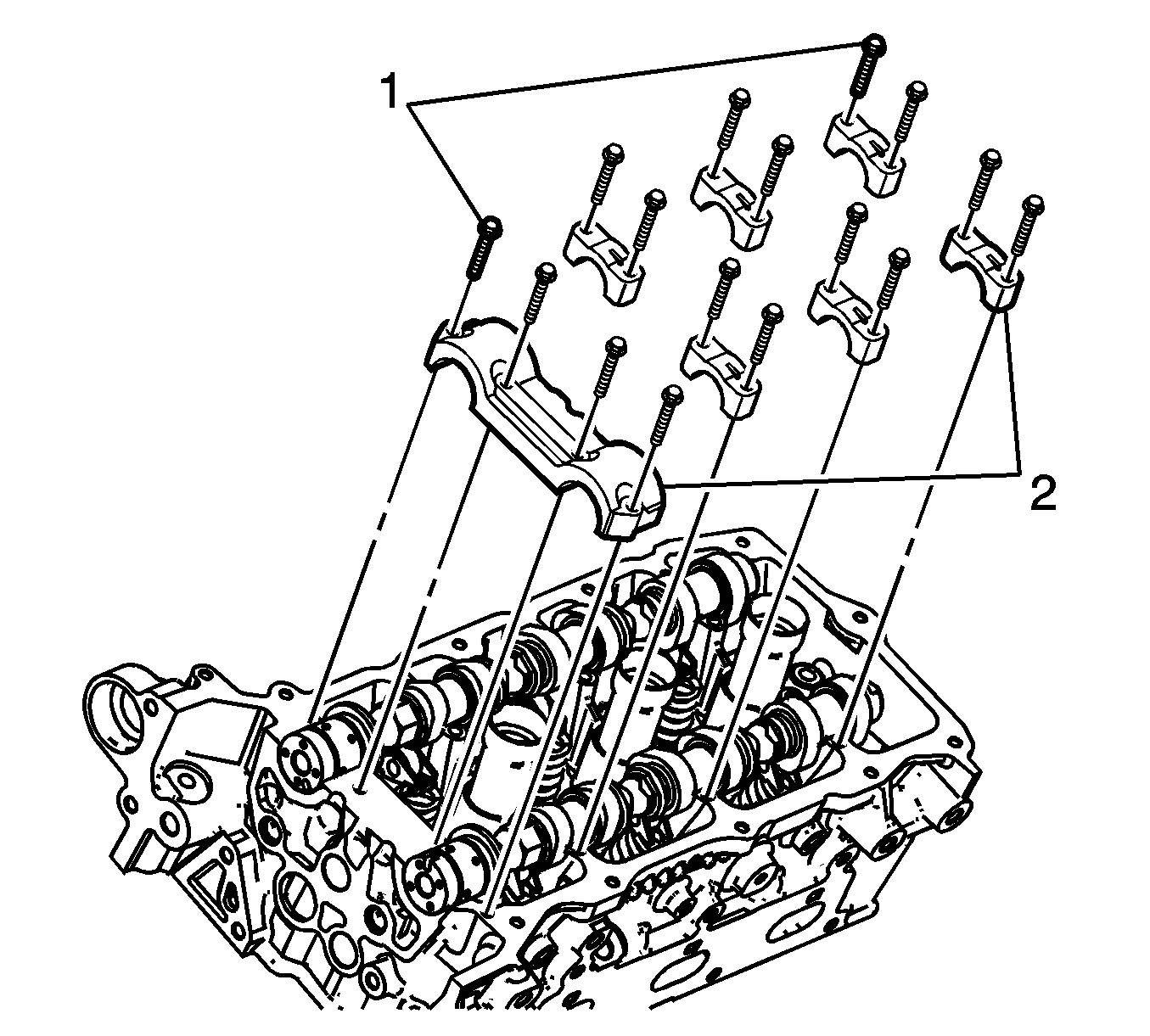
- Remove the camshaft bearing cap bolts (1) and caps (2).
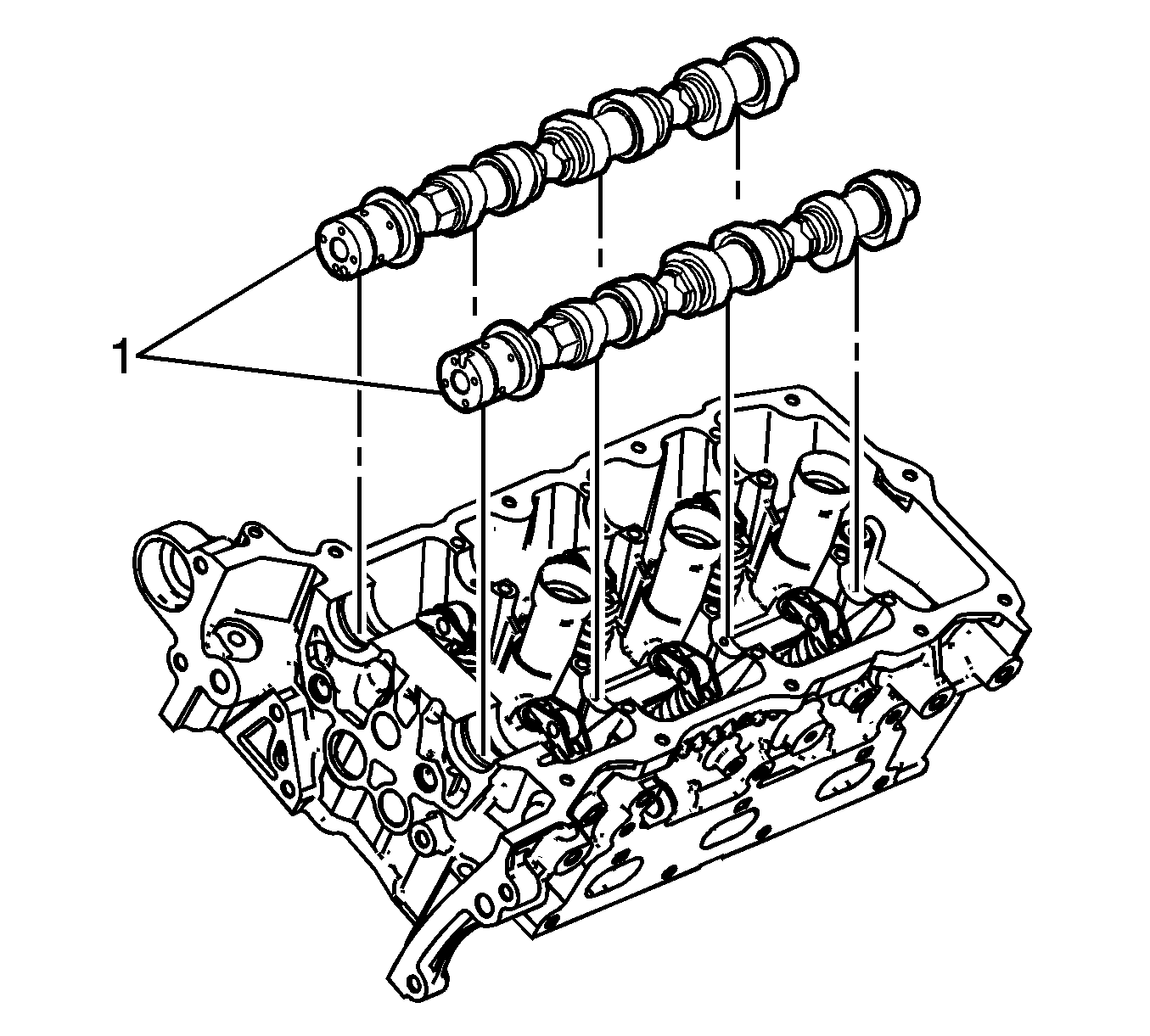
- Remove the camshafts (1).
- Clean the camshaft in solvent and dry it with compressed air.
- Inspect the camshaft. Refer to Camshaft Cleaning and Inspection.
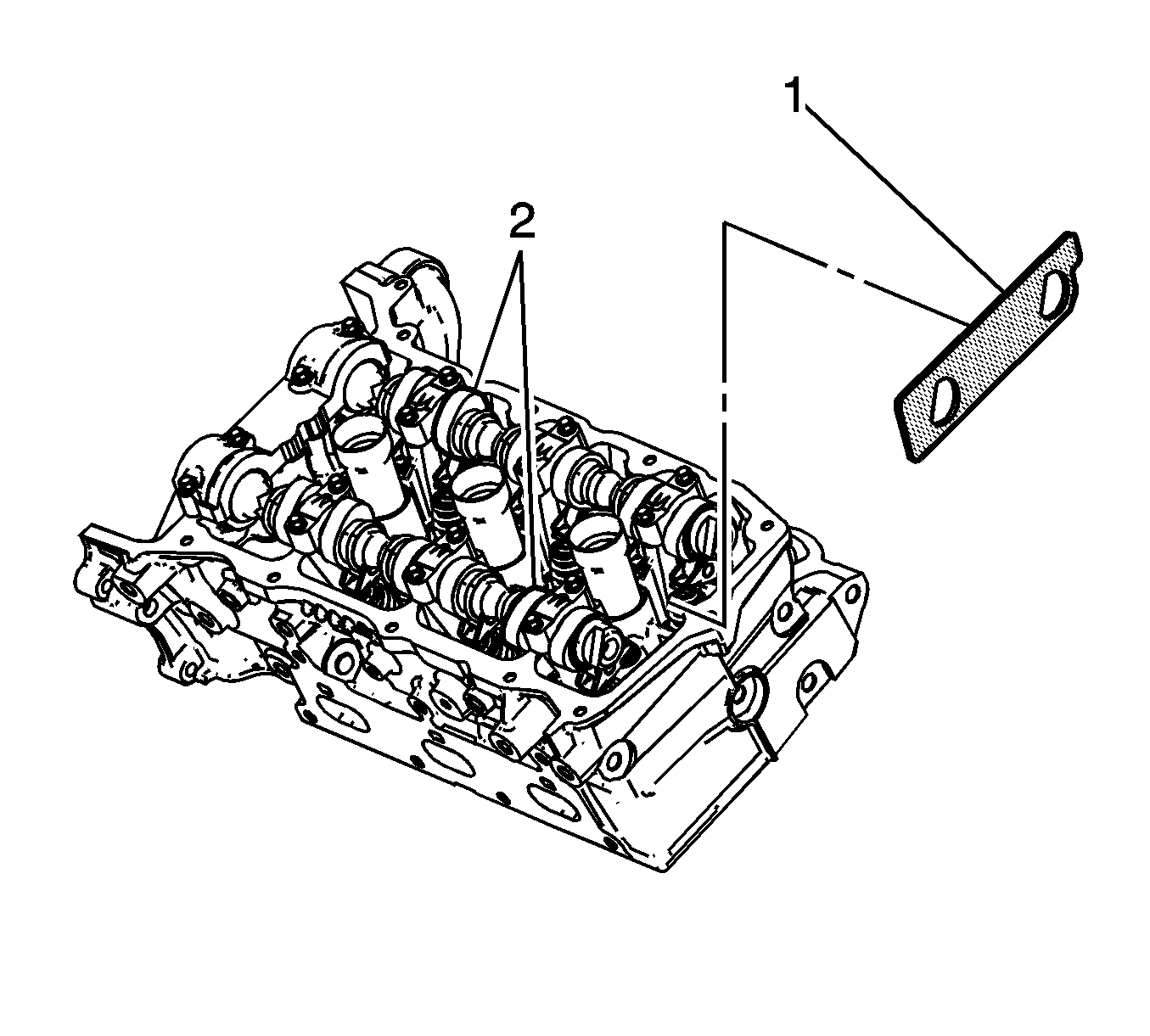
Note: Install the EN-46105 tool as part of the bank 2 cylinder head camshaft position actuator removal procedure.
| • | The raised feature must always be oriented toward the center of the cylinder head. |
| • | An I indicates the intake camshaft. |
| • | An E indicates the exhaust camshaft. |
| • | The number indicates the journal position from the front of the engine. |
Installation Procedure
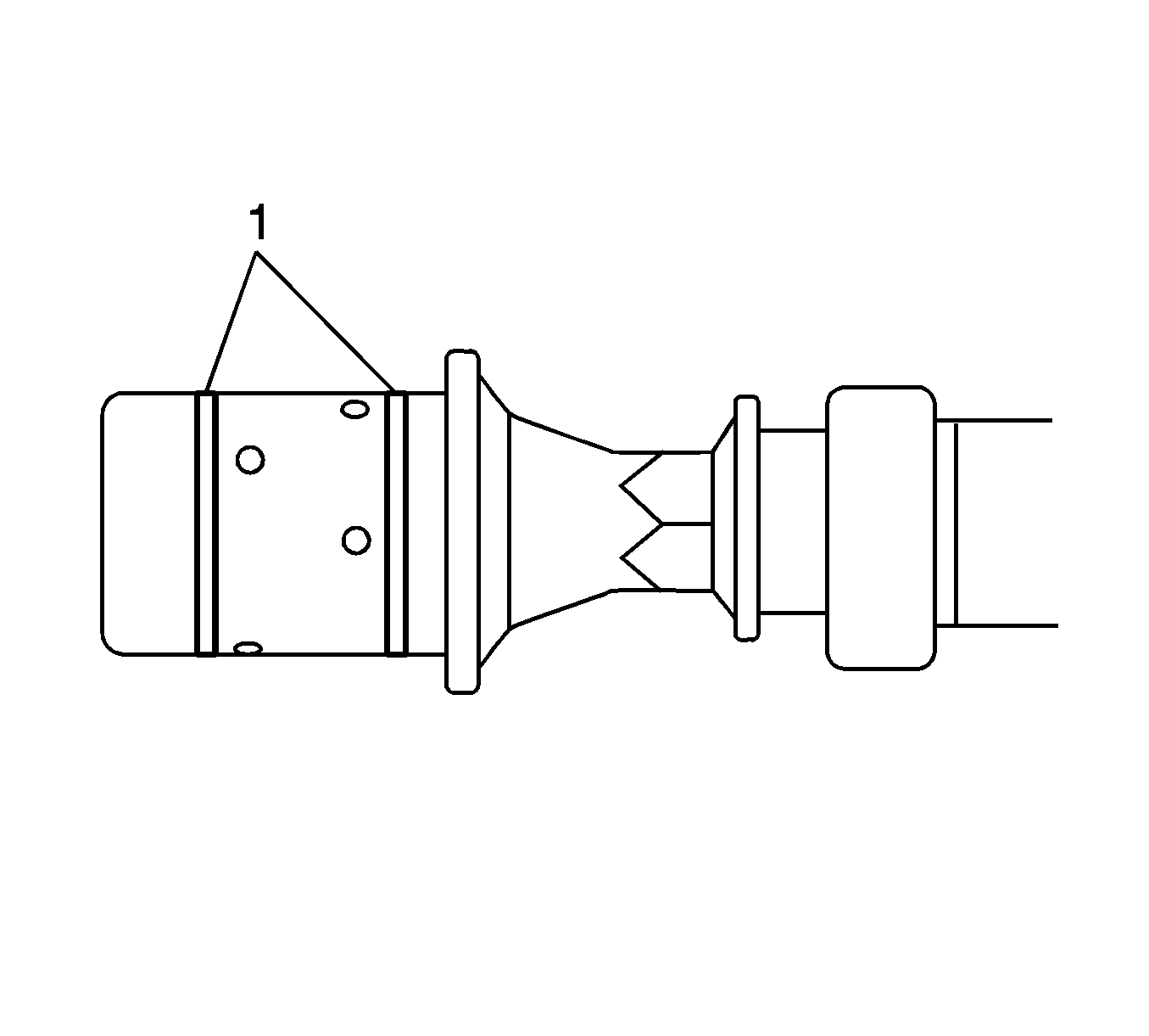
- Ensure the camshaft sealing rings (1) are in place in the camshaft grooves.
- Select the correct camshaft for the particular installation location. ID markings can be found on the rear end of each camshaft. The ID markings are defined as follows:
- Apply a liberal amount of engine oil to the camshaft journals and the bank 2 cylinder head camshaft carriers.
- Position the camshafts (1) on the cylinder head to the camshafts.
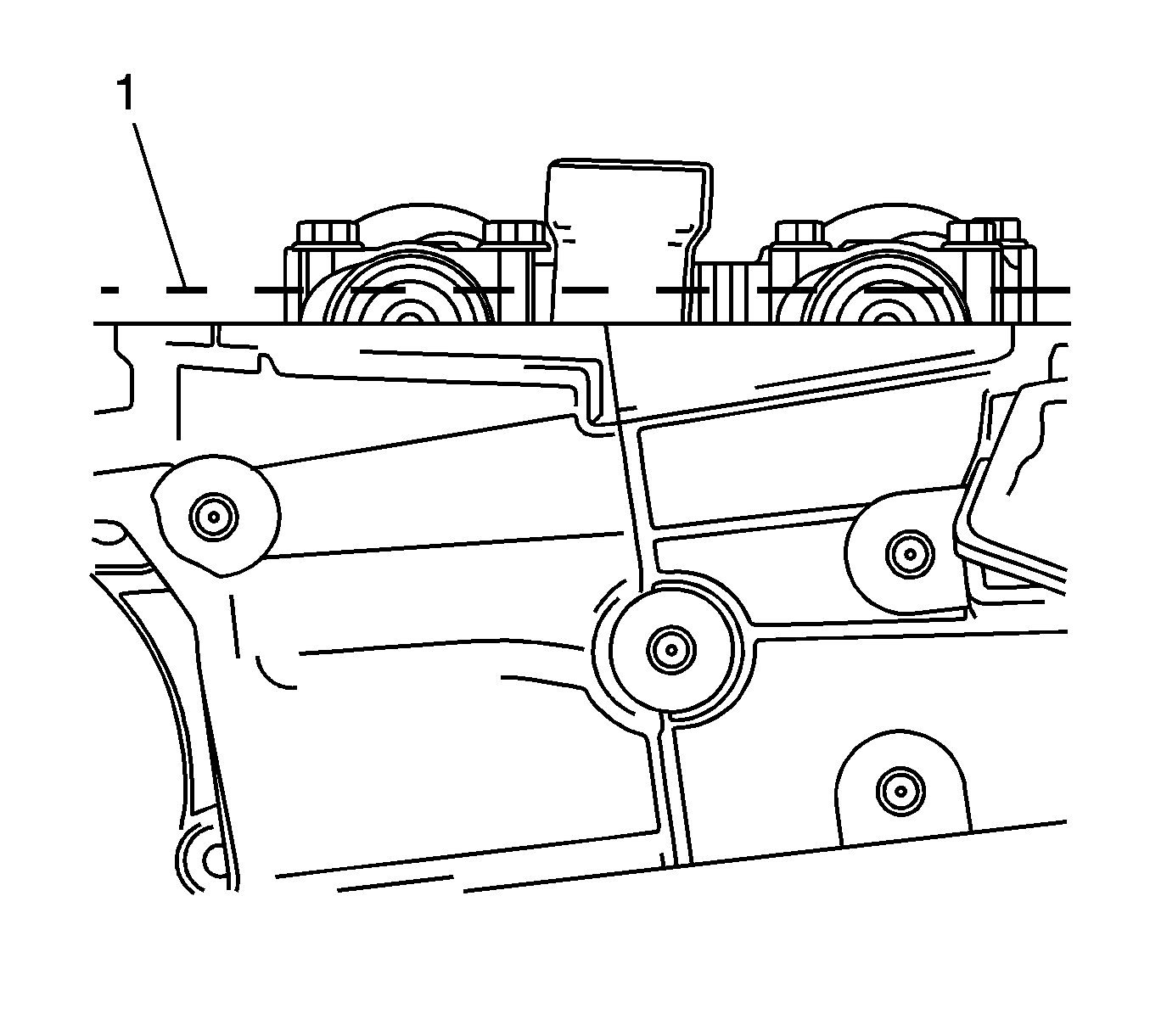
- Ensure the camshaft lobes are in the neutral position with the flats on the back of the camshafts up and parallel (1) with the bank 2 cylinder head cylinder head cover rail.
- Ensure the marks on the bank 2 exhaust camshaft position actuator and timing chain, made prior to the disassemble operation are aligned.
- Ensure the marks on the bank 2 intake camshaft position actuator and timing chain, made prior to the disassemble operation are aligned.
- Observe the markings on the bank 2 cylinder head camshaft bearing caps. Each bearing cap is marked (1) to identify its location. The markings have the following meanings:
- Apply a liberal amount of engine oil to the camshaft bearing caps.
- Install the camshaft bearing thrust cap (1) in the first journal of the bank 2 cylinder head.
- Install the remaining bearing caps (2) with their orientation mark toward the center of the cylinder head.
- Hand starts all the camshaft bearing cap bolts (1).
- Install the camshaft bearing cap bolts and tighten to 10 N·m (89 lb in).
- Loosen the center intake camshaft bearing cap bolts 1, 2 and the center exhaust camshaft bearing cap bolts 3 and 4.
- Retighten the center camshaft bearing cap bolts 1, 2, 3 and 4 to 10 N·m (89 lb in).
- Install the bank 2 cylinder head camshaft position actuators. Refer to Camshaft Position Actuator Replacement - Bank 2 (Left Side) Exhaust and Camshaft Position Actuator Replacement - Bank 2 (Left Side) Intake.

| • | The first five digits refer to the date and time of production. |
| • | Example = 3L18H |
| • | Digits six through nine refer to engine production code |
| • | LY7 = Alloytec 190 engine |
| • | The last two digits refer to position: |
| • | LI = bank 2 intake |
| • | LE = bank 2 exhaust |
| • | RI = bank 1 intake |
| • | RE = bank 1 exhaust |
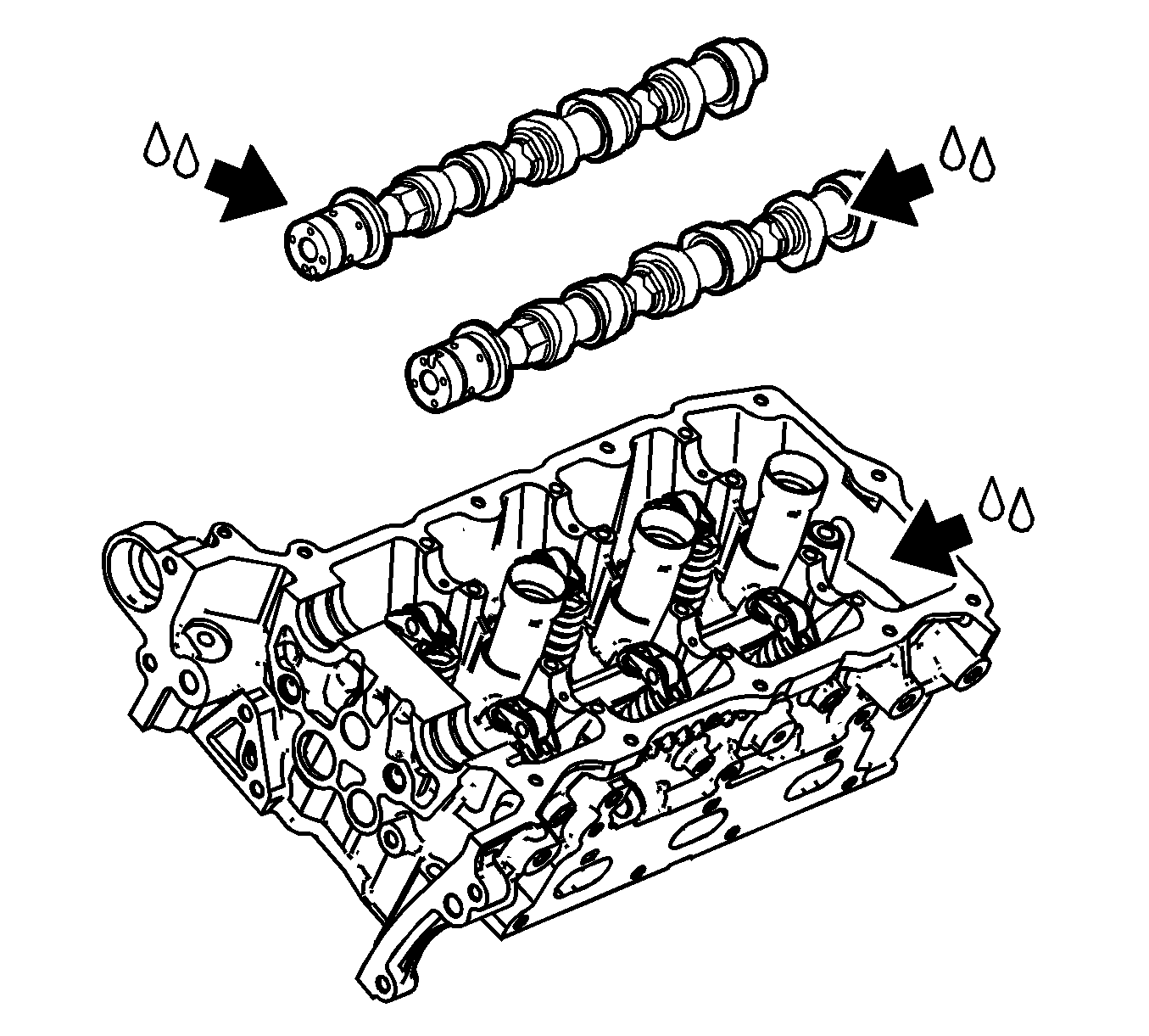

Note: Install the camshaft position actuator bolts but do not tighten at this stage.
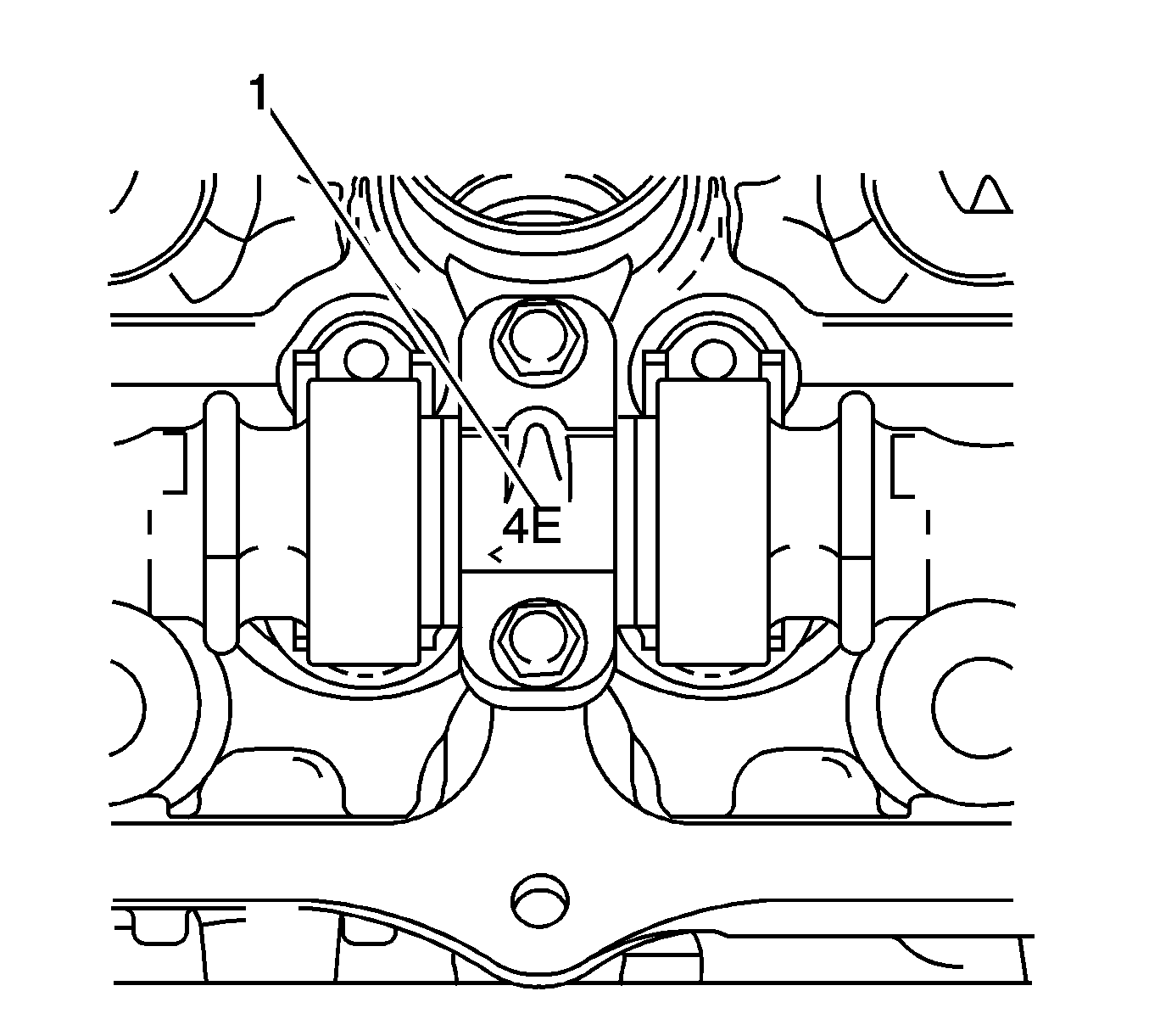
| • | The raised feature must always be oriented toward the center of the cylinder head. |
| • | The I indicates the intake camshaft |
| • | The E indicates the exhaust camshaft. |
| • | The number 2, 4, 6 indicates the cylinder position from the front of the engine. |

Caution: Refer to Fastener Caution in the Preface section.

