Removal Procedure
Notice: In order to prevent internal damage to the PCM, the ignition must be OFF when disconnecting or reconnecting the PCM connector.
Service should normally consist of either replacement of the PCM or EEPROM re-programming.
If the diagnostic procedures call for the PCM to be replaced, the PCM should be inspected first in order to verify the PCM is the correct part. DTC P0602 indicates the EEPROM programming has malfunctioned. When DTC P0602 is set, re-program the EEPROM.
- Disconnect the negative battery cable. Refer to Battery Negative Cable Disconnection and Connection in Engine Electrical in the J Platform Service Manual.
- Push down the locking tab and pull up on the release lever and disconnect the PCM harness connectors.
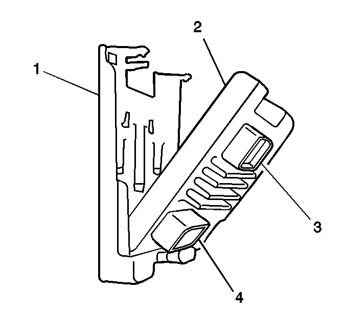
- Depress the PCM retaining tabs (1).
- Lift the PCM (2) from the PCM bracket.
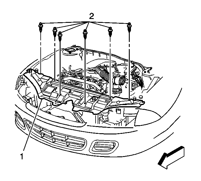
- Remove the hood close-out filler panel (1) push pin retainers (2).
- Remove the hood close-out filler panel (1).
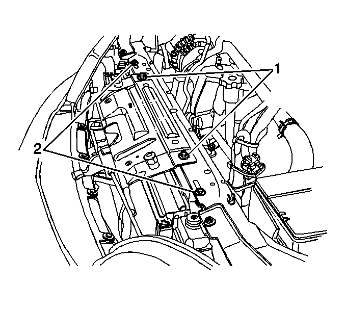
- Remove the upper hood latch support bolts (1).
- Remove the upper radiator mount bolts (2).
- Angle the radiator towards the front of the vehicle in order to allow sufficient clearance for PCM bracket removal.
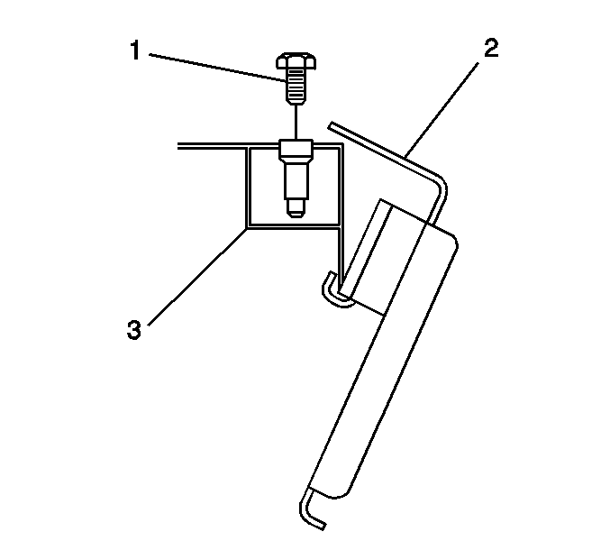
- Remove the PCM mounting bracket (2) retaining bolts (1).
- Angle the PCM mounting bracket (2) away from the radiator core support (3) and remove the PCM mounting bracket from the vehicle.

Notice: Do not touch the PCM connector pins or soldered components on the circuit board in order to prevent possible electrostatic discharge (ESD) damage. Do not remove the integrated circuit boards from the carrier.
Proceed to the next step if PCM bracket removal is required.


Installation Procedure
- If PCM bracket replacement is not being performed proceed to step 9.
- Angle the PCM mounting bracket (2) onto the radiator core support (3).
- Install the PCM mounting bracket (2) retaining bolts (1).
- Angle the radiator towards the rear of the vehicle in order to allow the installation of the upper radiator mounting bolts.
- Install the upper radiator mount bolts (2).
- Install the upper hood latch support bolts (1).
- Install the hood close-out filler panel (1).
- Install the hood close-out filler panel (1) push-pin retainers (2).
- Remove the new PCM from the packaging and inspect the service number to verify the number is the same number, or an updated number, as the faulty PCM.
- Push the PCM (2) into the PCM bracket (1). The retaining tab will lock in place.
- Install the PCM harness connectors and lock down the release levers.
- Connect the negative battery cable. Refer to Battery Negative Cable Disconnection and Connection in Engine Electrical in the J Platform Service Manual.
- Program the PCM. Refer to Powertrain Control Module Programming in Engine Controls in the J Platform Service Manual.

Engage the PCM mounting bracket (2) lip onto the radiator core support (3).
Notice: Use the correct fastener in the correct location. Replacement fasteners must be the correct part number for that application. Fasteners requiring replacement or fasteners requiring the use of thread locking compound or sealant are identified in the service procedure. Do not use paints, lubricants, or corrosion inhibitors on fasteners or fastener joint surfaces unless specified. These coatings affect fastener torque and joint clamping force and may damage the fastener. Use the correct tightening sequence and specifications when installing fasteners in order to avoid damage to parts and systems.
Tighten
Tighten the bolts to 10 N·m(89 lb in).

Tighten
Tighten the bolts to 10 N·m (89 lb in).
Tighten
Tighten the bolts to 9 N·m (80 lb in).


Notice: Do not touch the PCM connector pins or soldered components on the circuit board in order to prevent possible electrostatic discharge (ESD) damage. Do not remove the integrated circuit boards from the carrier.
Important: : The replacement PCM must be reprogrammed and the crankshaft position system variation learn procedure must be performed.
