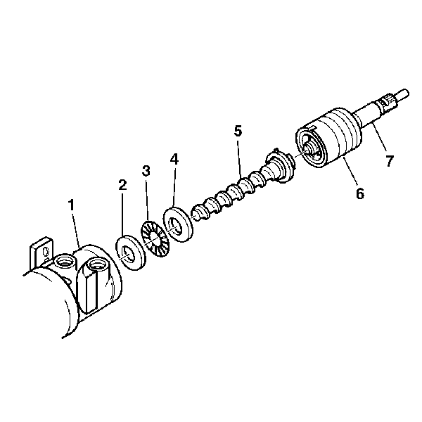
For 1990-2009 cars only
Disassembly Procedure
- Remove the steering gear thrust support. Refer to Steering Gear Worm Gear Adjuster Seal and Stub Shaft Bearing Replacement .
- Remove the stub shaft and the valve assembly from the steering gear housing.
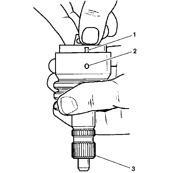
- Remove the stub shaft O-ring seal from the stub shaft cap end (1).
- If necessary, remove the stub shaft from the valve body (2) by performing the following:
- If the valve assembly needs repair, disassemble the valve as follows:
- Inspect the O-ring seals (4) and the valve body rings (5).
- If one or more of the following items occur, replace the valve assembly:
- If one or more of the following items occur, replace the stub shaft assembly and the valve assembly:
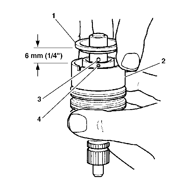
| 4.1. | Tap the stub shaft lightly on a wood block in order to loosen the shaft cap. |
| 4.2. | Pull the shaft cap and the valve spool out from valve body 6 mm (¼ inch). |
| 4.3. | Disengage the stub shaft pin (3) from the hole in the valve spool (4). |
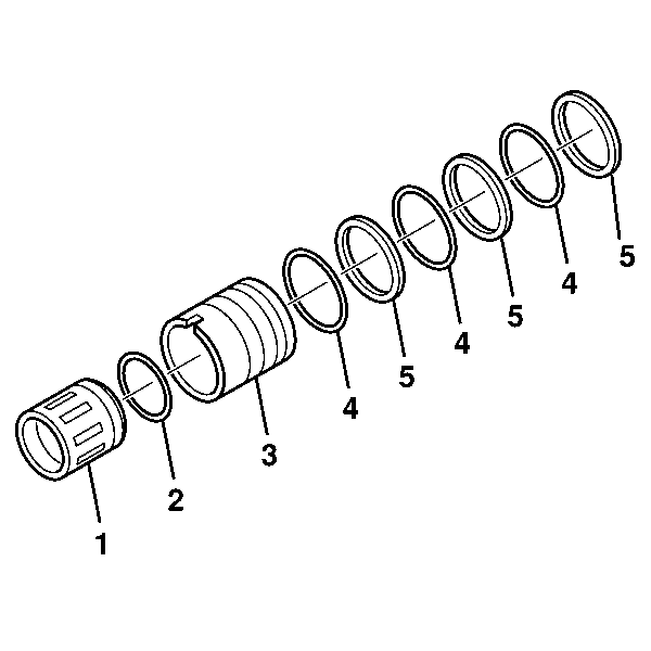
| 5.1. | Simultaneously pull and rotate the valve spool (1) in order to remove the valve spool (1) from the valve body (3). |
| 5.2. | Remove the valve spool O-ring seal (2). |
| 5.3. | Alternately remove the valve body rings (5) and the O-ring seals (4). |
| • | The torsion bar and the stub shaft leak. |
| • | The ground surface of the stub shaft contains nicks or burrs. |
| • | The small notch in the skirt of the valve is worn. |
| • | The stub shaft pin contains wear or cracks. |
| • | The outside diameter of the valve spool contains nicks or burrs. |
| • | The inside diameter of the valve body contains nicks or burrs. |
| • | The valve spool (1) binds when rotated. |
Assembly Procedure
- If disassembled, reassemble the valve assembly in the following manner:
- Simultaneously push and rotate the valve spool (2) into the valve body (1) until the hole (3) in the valve spool (2) for the stub shaft pin is accessible from the opposite end of the valve body (1).
- If necessary, install the stub shaft to the valve spool in the following manner:
- Install the stub shaft (7) and valve assembly (6) to the worm shaft (5). Ensure the pin fits in the worm shaft to the slot in the valve assembly.
- Install the thrust support assembly. Refer to Steering Gear Worm Gear Adjuster Seal and Stub Shaft Bearing Replacement .

| 1.1. | Alternately install the valve body rings (5) and the O-ring seals (4). |
| 1.2. | Install the valve spool O-ring seal (2) to the valve spool (1). |
| 1.3. | Lubricate the valve spool (1) and O-ring seal (2) with power steering fluid. |
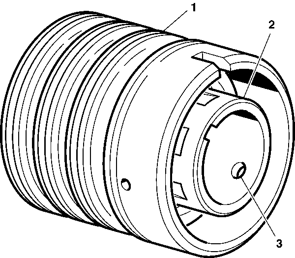
Lubricate the stub shaft assembly (3).
| 3.1. | Insert the stub shaft (3) into the valve spool. |
| 3.2. | Insert the pin. |
| Important: Make sure that the shaft cap notch (1) is mated with the valve body pin before installing the valve body into the steering gear assembly. |
| 3.3. | The notch in the cap (1) must fully engage the valve body pin (2). Seat the cap against the valve body shoulder. |
