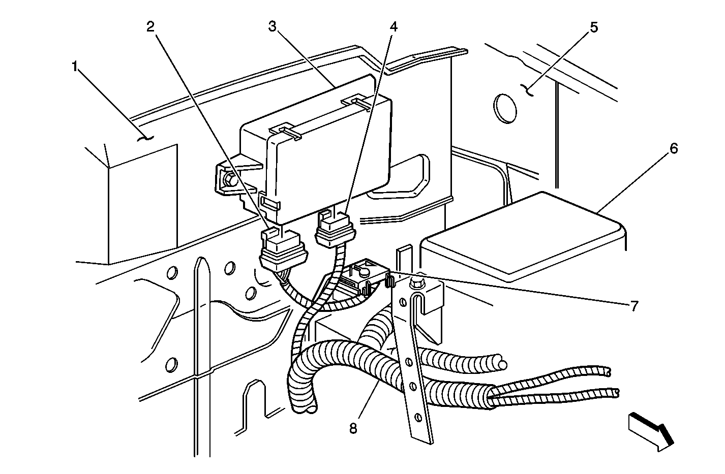
| Figure 1: |
Throttle Actuator Control (TAC) Module
|
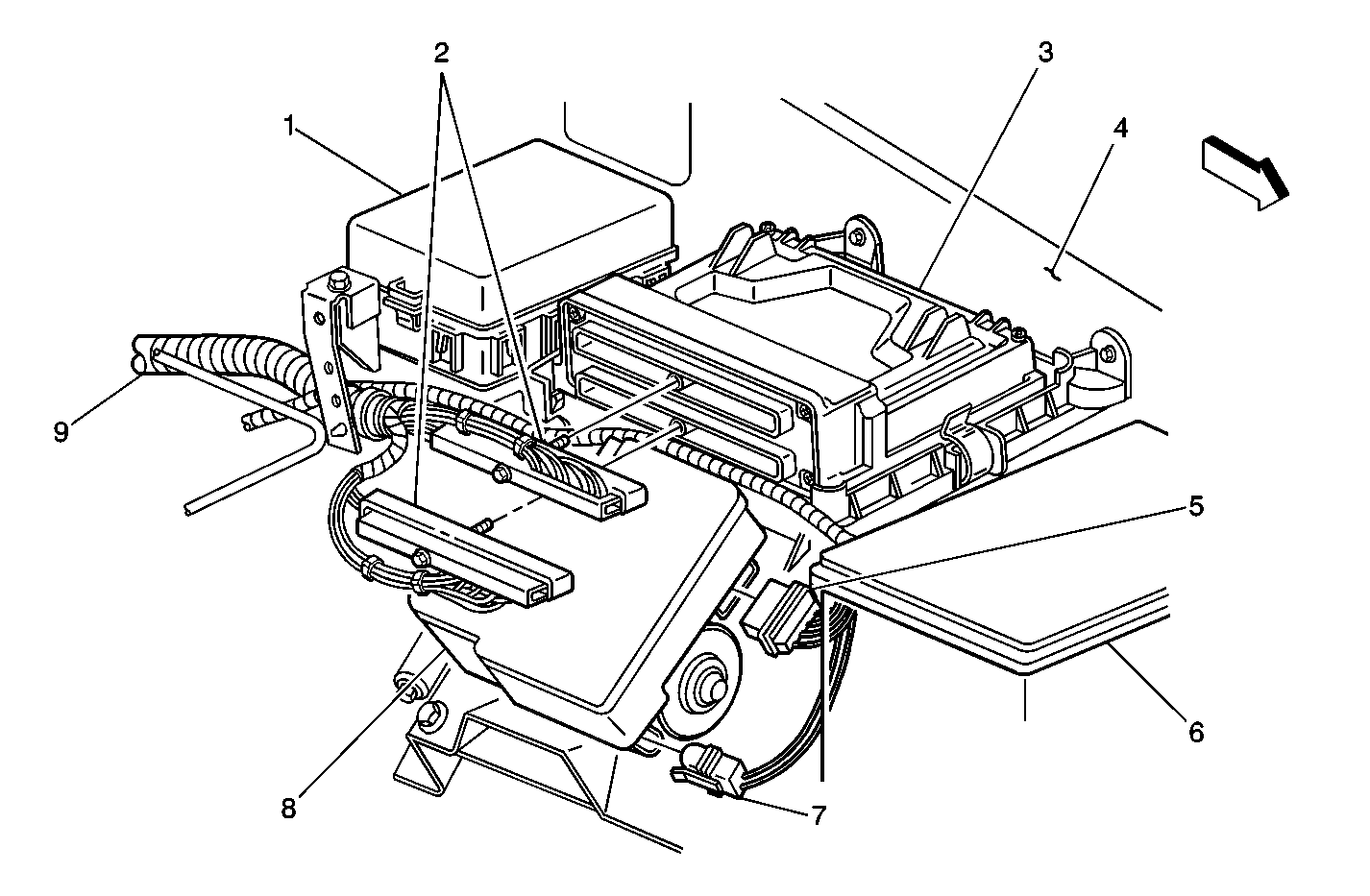
| Figure 2: |
Fuse Block - Underhood, PCM, EBCM, and Aux Battery
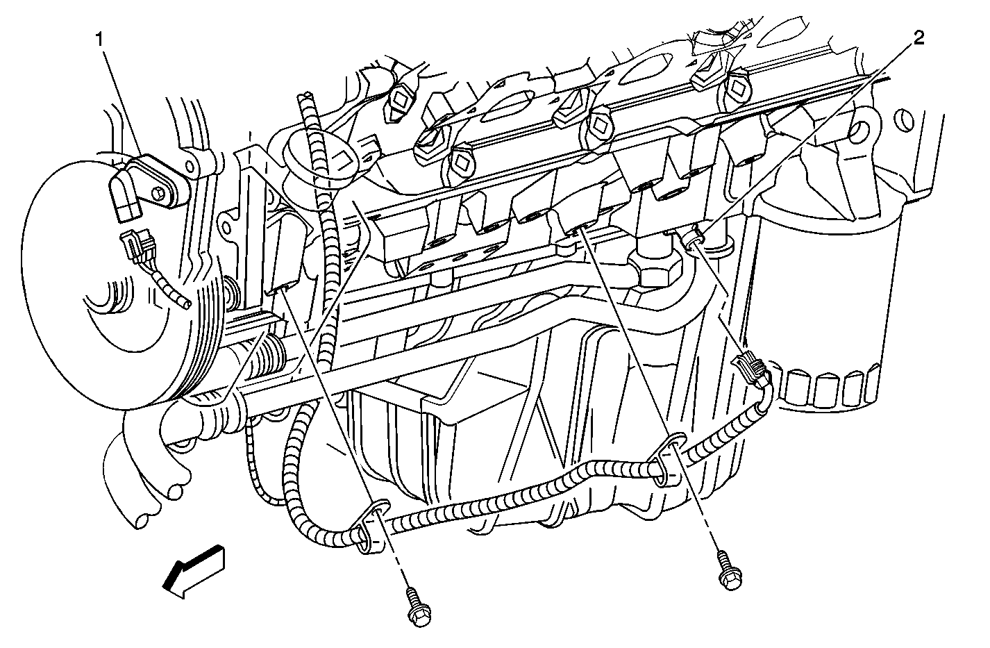
|
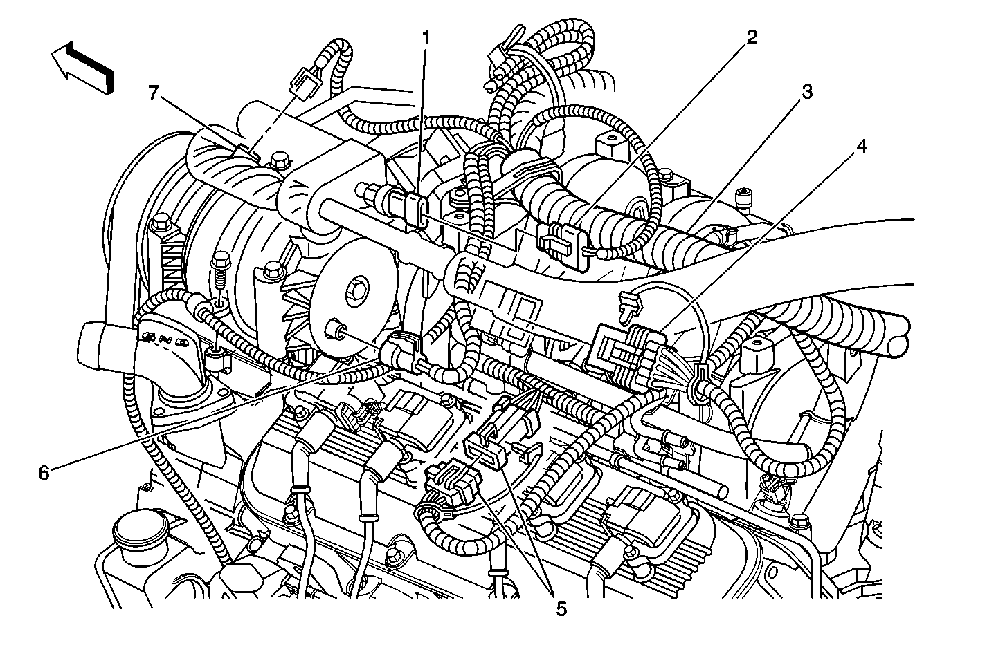
| Figure 3: |
A/C Compressor Connectors, C105, and C148
|
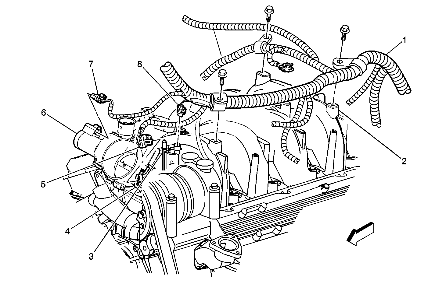
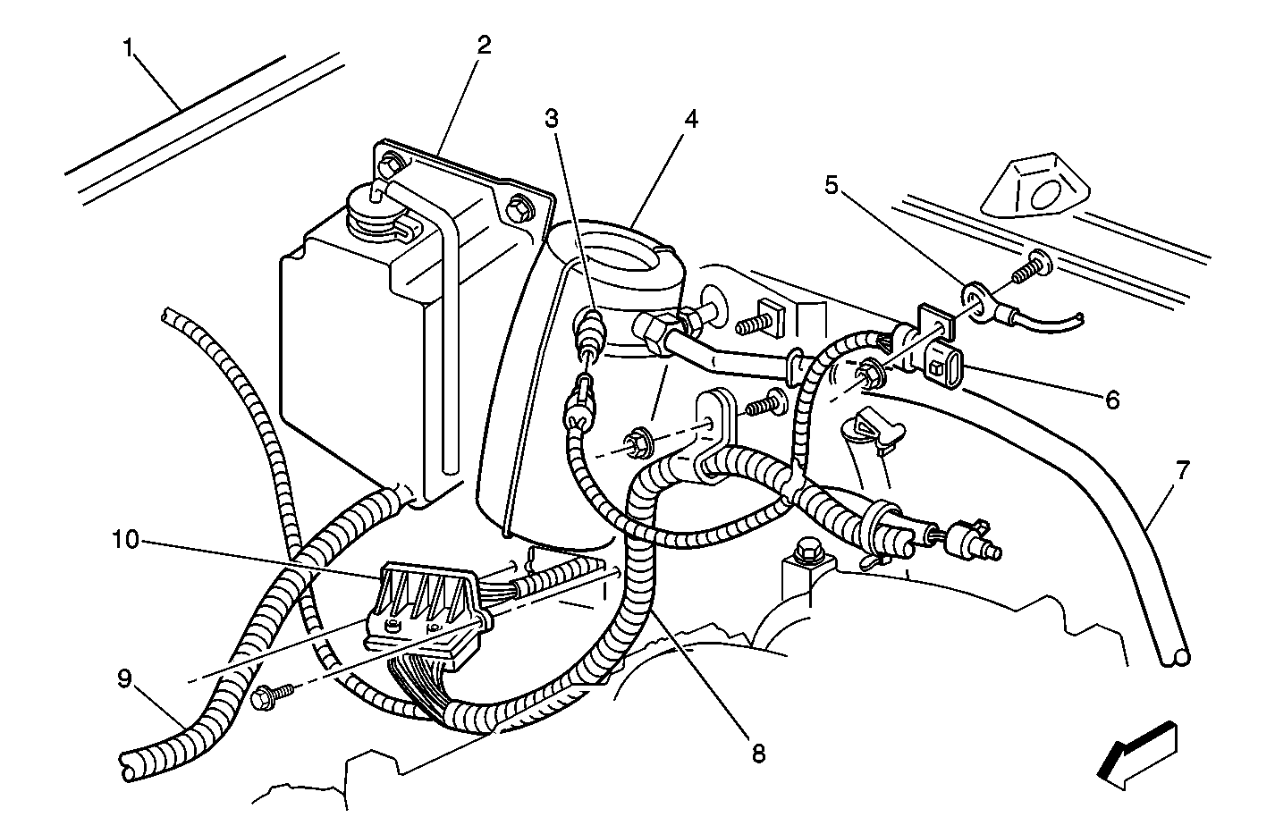
| Figure 4: |
Throttle Body and EVAP Control
|
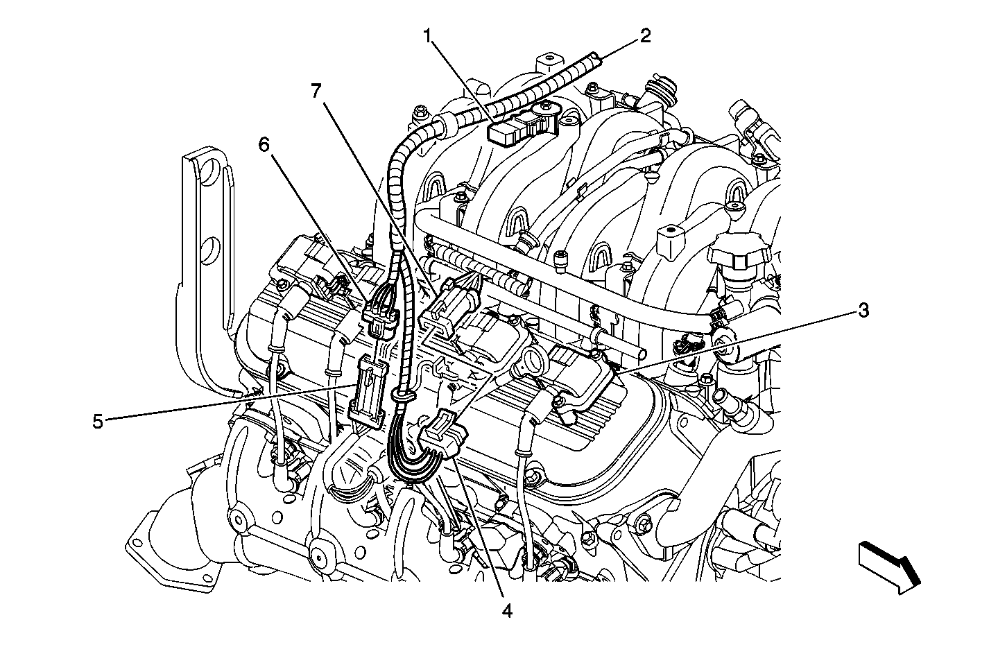
| Figure 5: |
Camshaft Position (CMP) Sensor and Knock Sensor (KS) - Left Side
|
| Figure 6: |
MAP Sensor, ECT Sensor, and Ignition Coils - Right Side
|
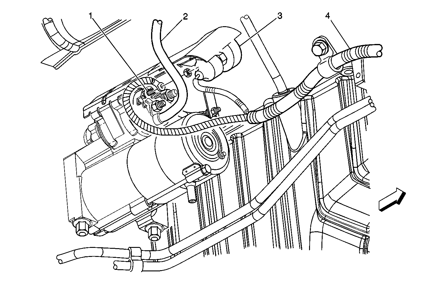
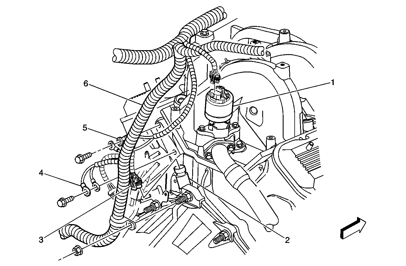
| Figure 7: |
Starter and Knock Sensor - Bank 2
|
| Figure 8: |
MAF and IAT Sensor
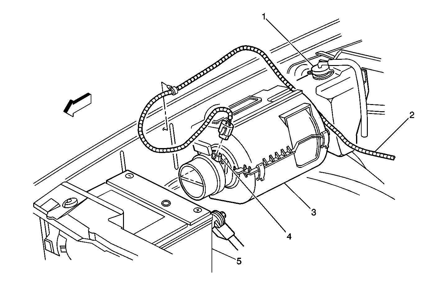
|
| Figure 9: |
P101, A/C Low Pressure Switch and G108
|
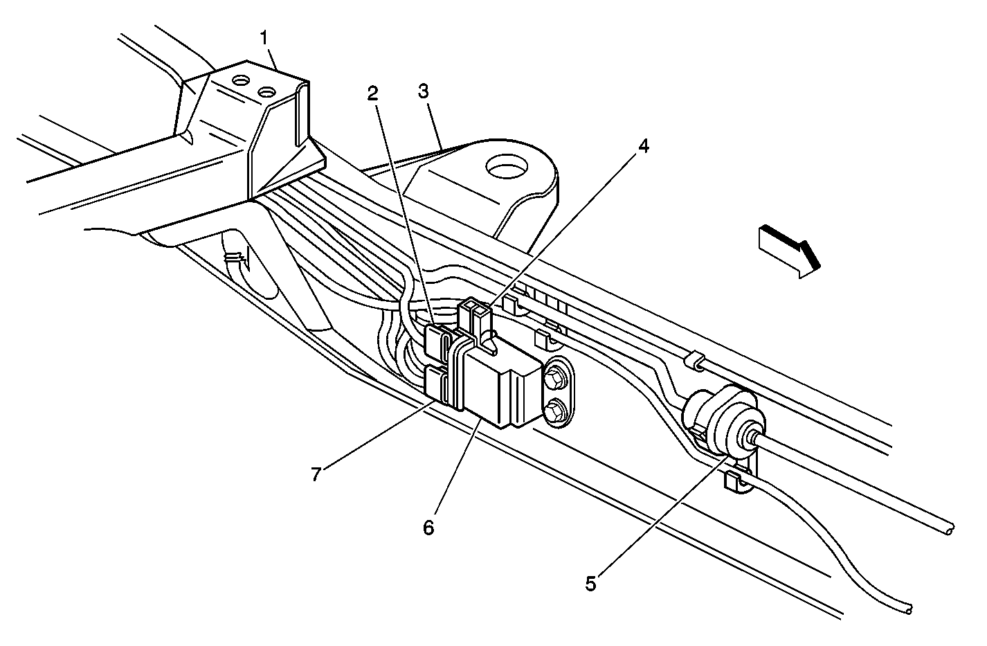
| Figure 10: |
EGR Valve, Engine Oil Pressure (EOP) Sensor, G104, and G105
|
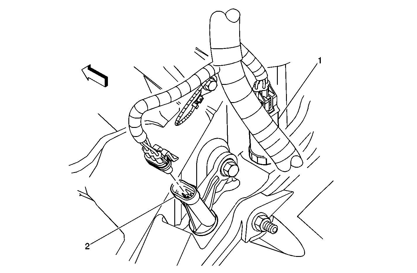
| Figure 11: |
Crankshaft Position (CKP) Sensor and Engine Oil Pressure (EOP) Sensor
|
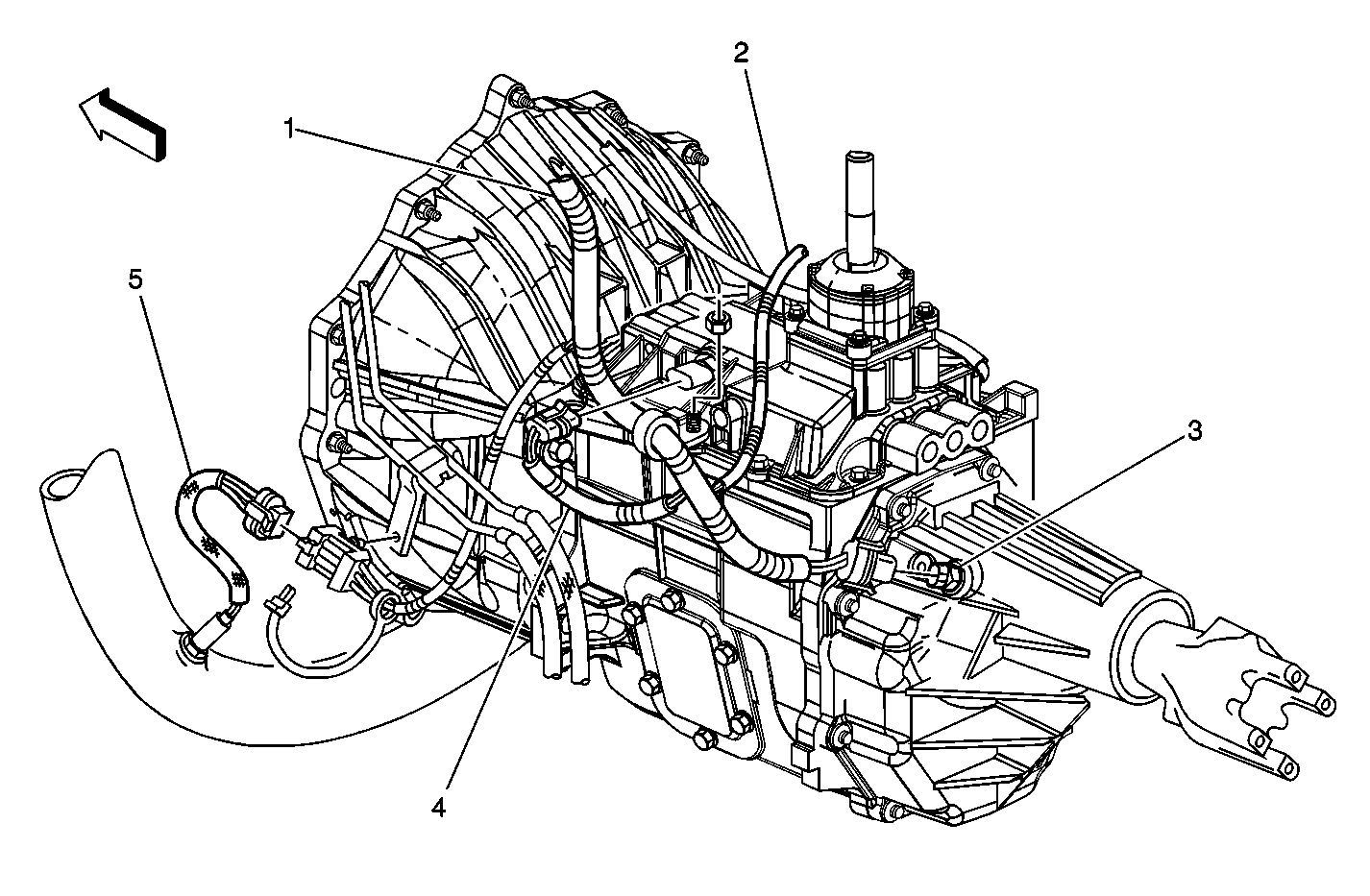
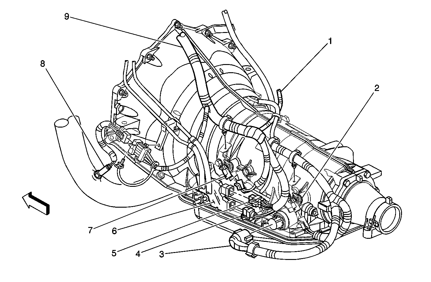
| Figure 12: |
Manual Transmission
|
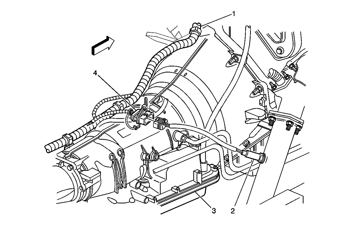
| Figure 13: |
Automatic Transmission
|
| Figure 14: |
Heated Oxygen Sensor (H02S) - Bank 2
|
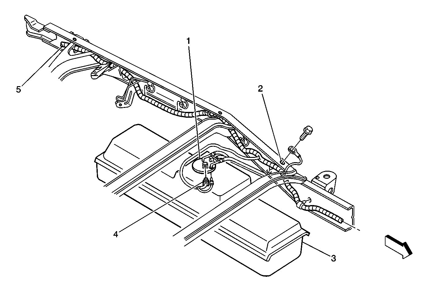
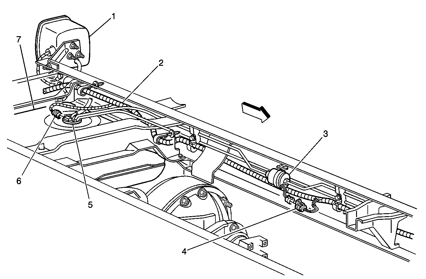
| Figure 15: |
Fuel Tank and G404
|
| Figure 16: |
Fuel Balance Module - Dual Tanks, and Fuel Filter
|
| Figure 17: |
Auxiliary Fuel Tank and Fuel Pump - Secondary - Dual Tank Option
|
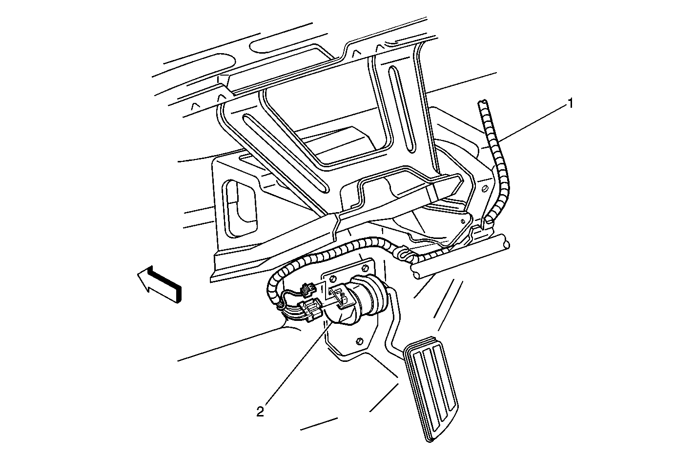
| Figure 18: |
Accelerator Pedal Position (APP) Sensor
|
| Figure 19: |
Data Link Connector (DLC)

|
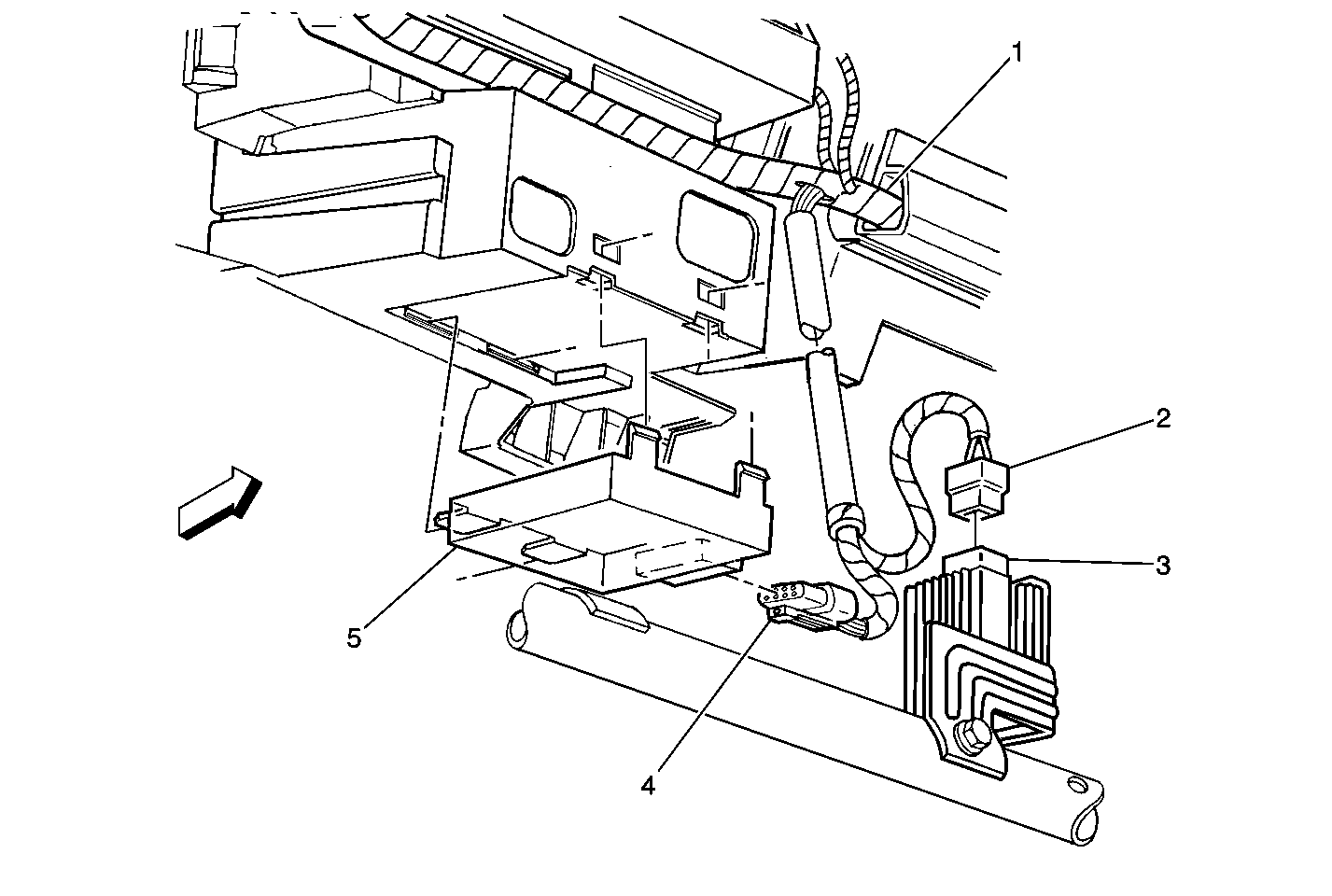
| Figure 20: |
Theft Deterrent Control Module and DRL Diode
|
