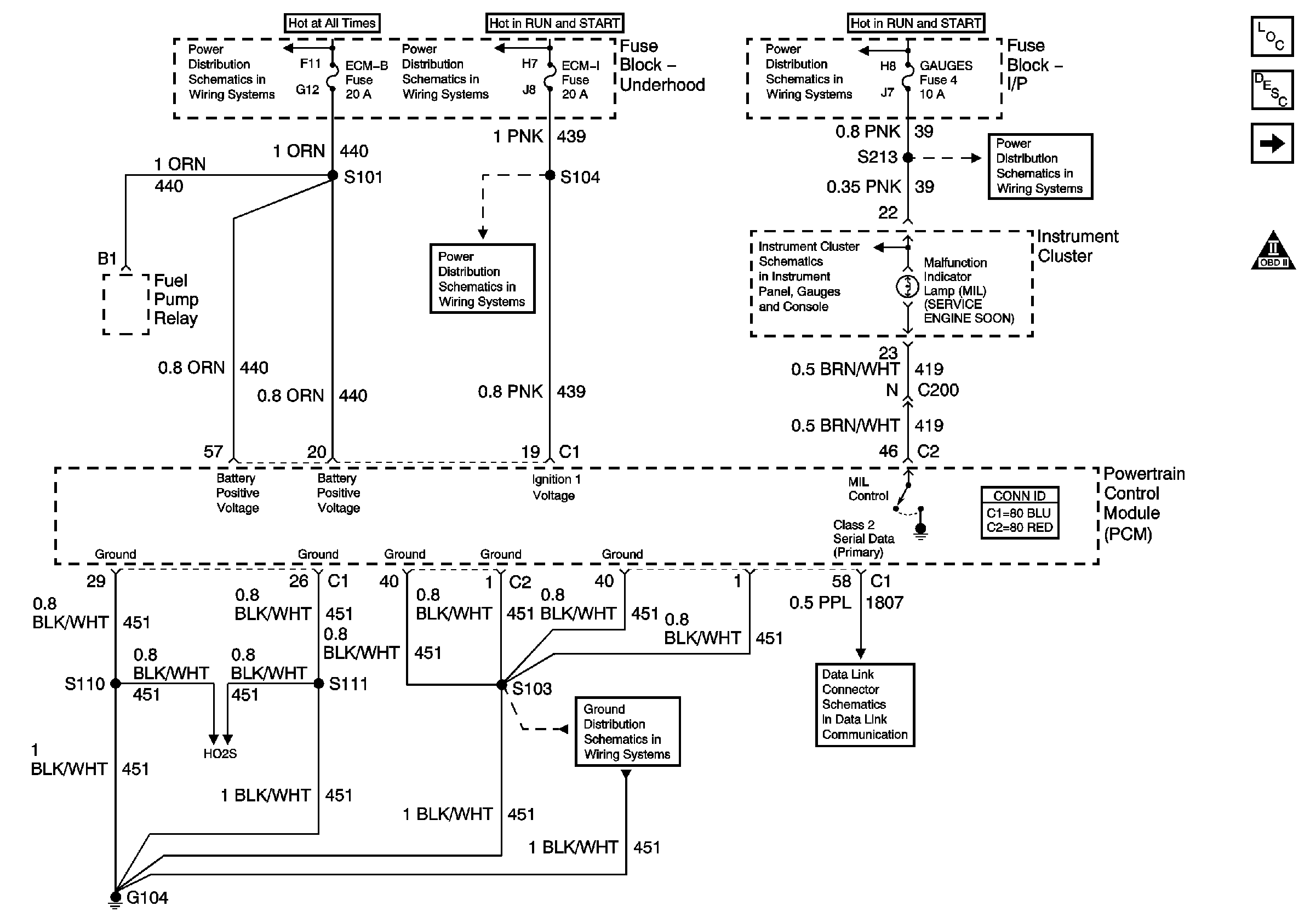
| Figure 1: |
PCM Power, Grounding, DLC, and MIL
|
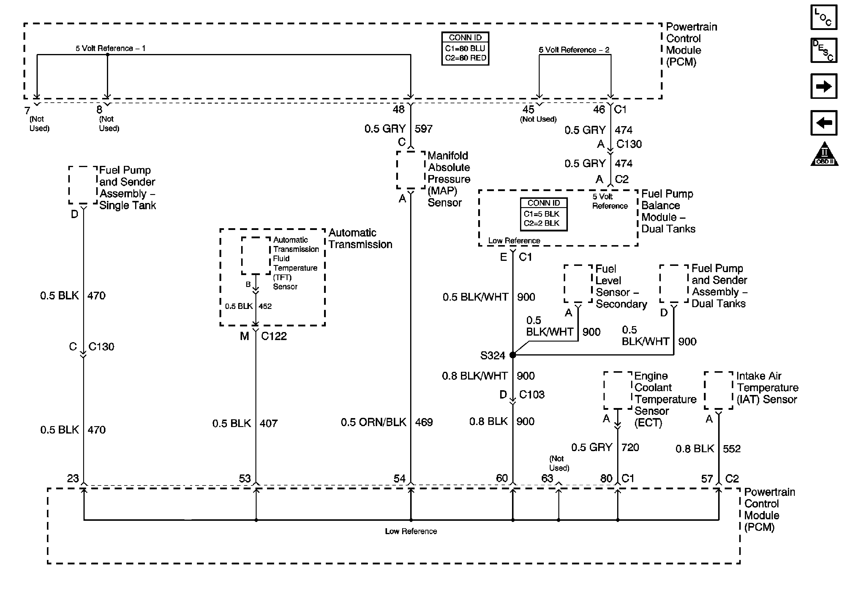
| Figure 2: |
5 Volt and Low Reference Busses
|
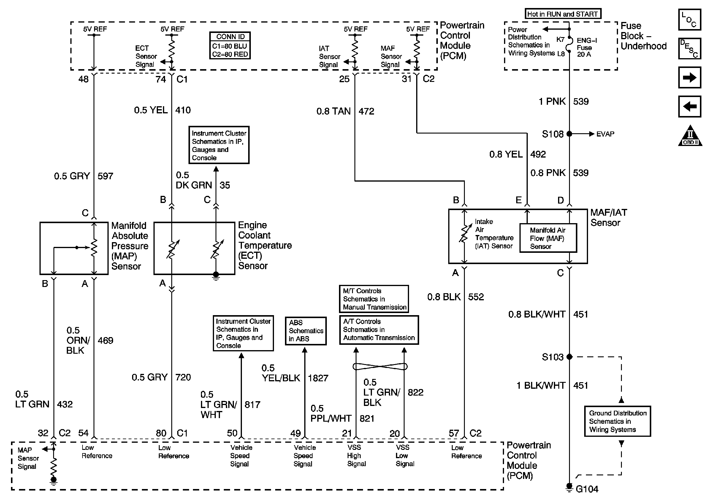
| Figure 3: |
MAP, ECT, VSS Circuit, and IAT/MAF
|
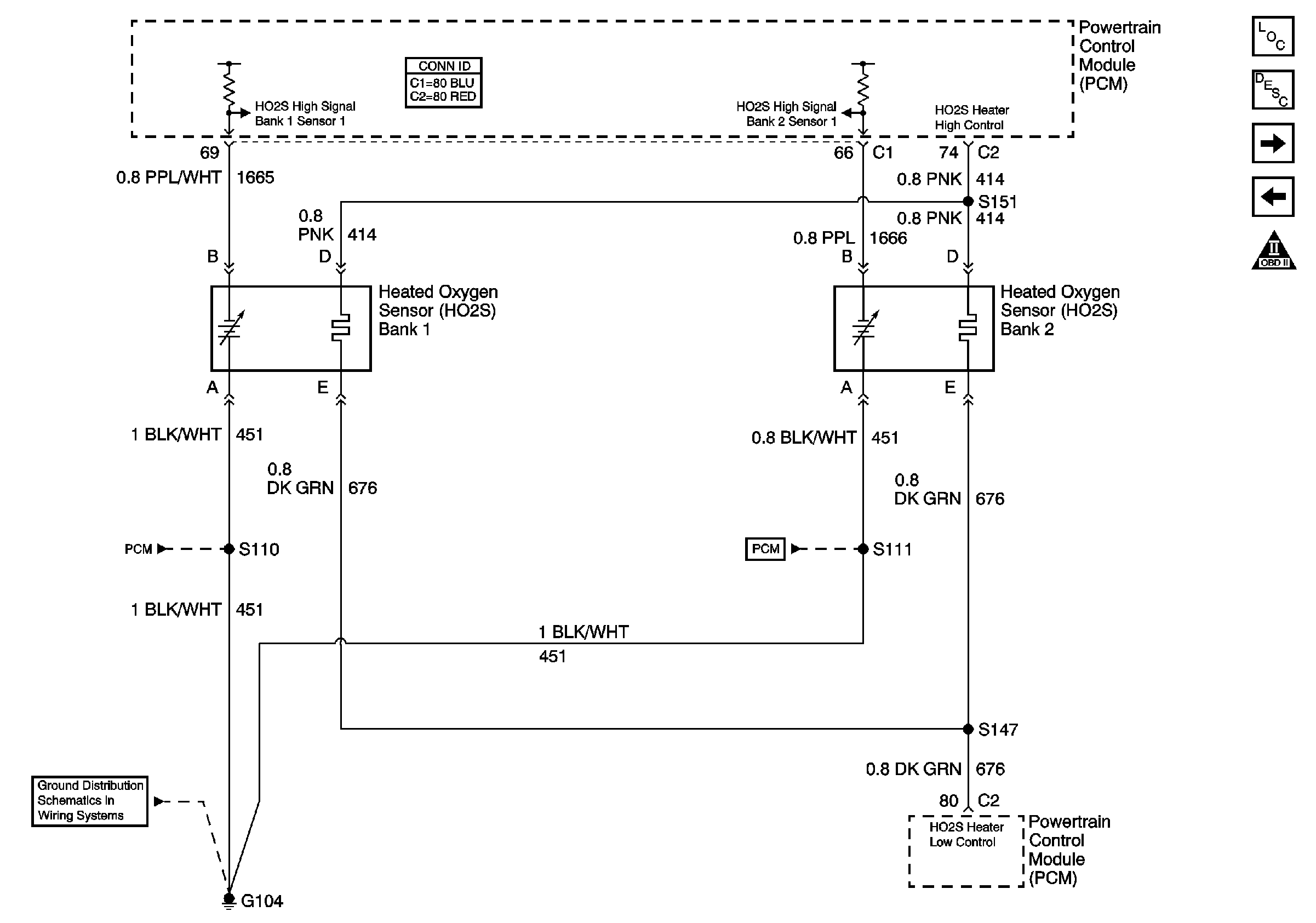
| Figure 4: |
HO2S Circuit
|
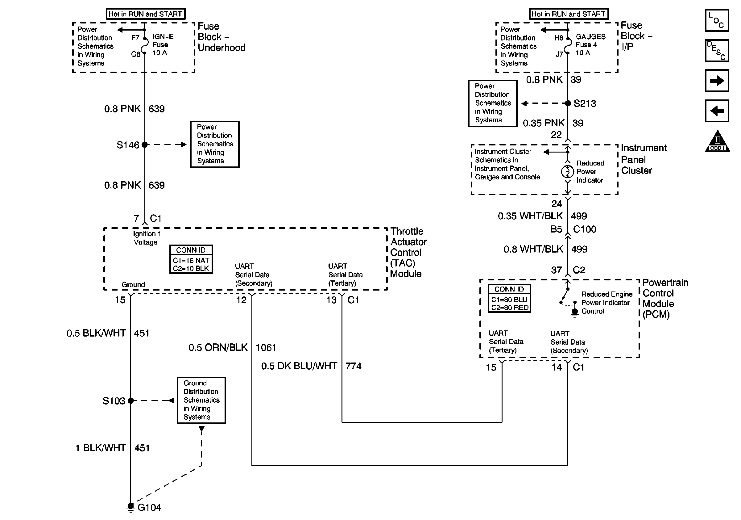
| Figure 5: |
TAC Power, Grounding, Data Circuits, and Indicator
Control
|
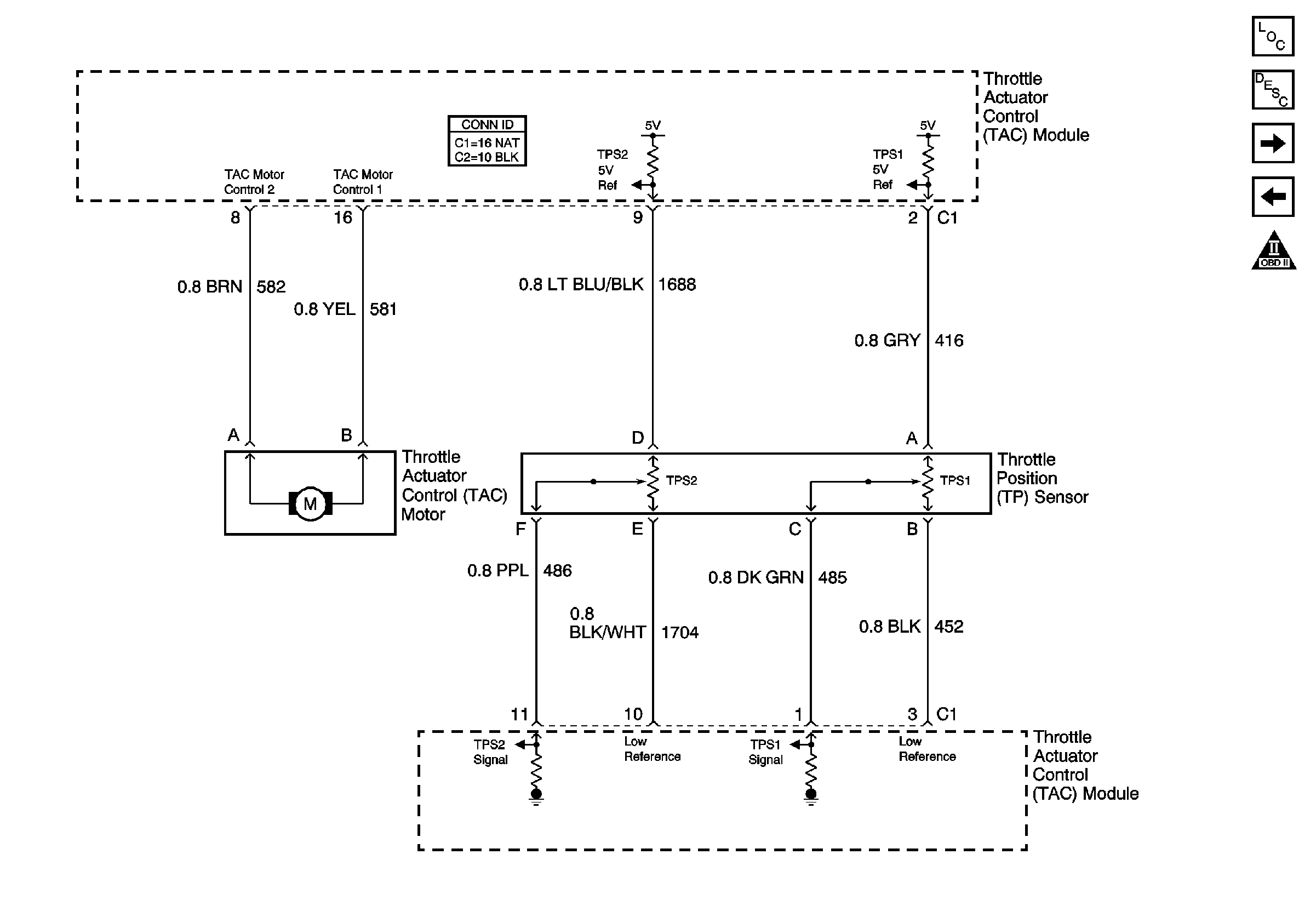
| Figure 6: |
Throttle Control Circuits
|
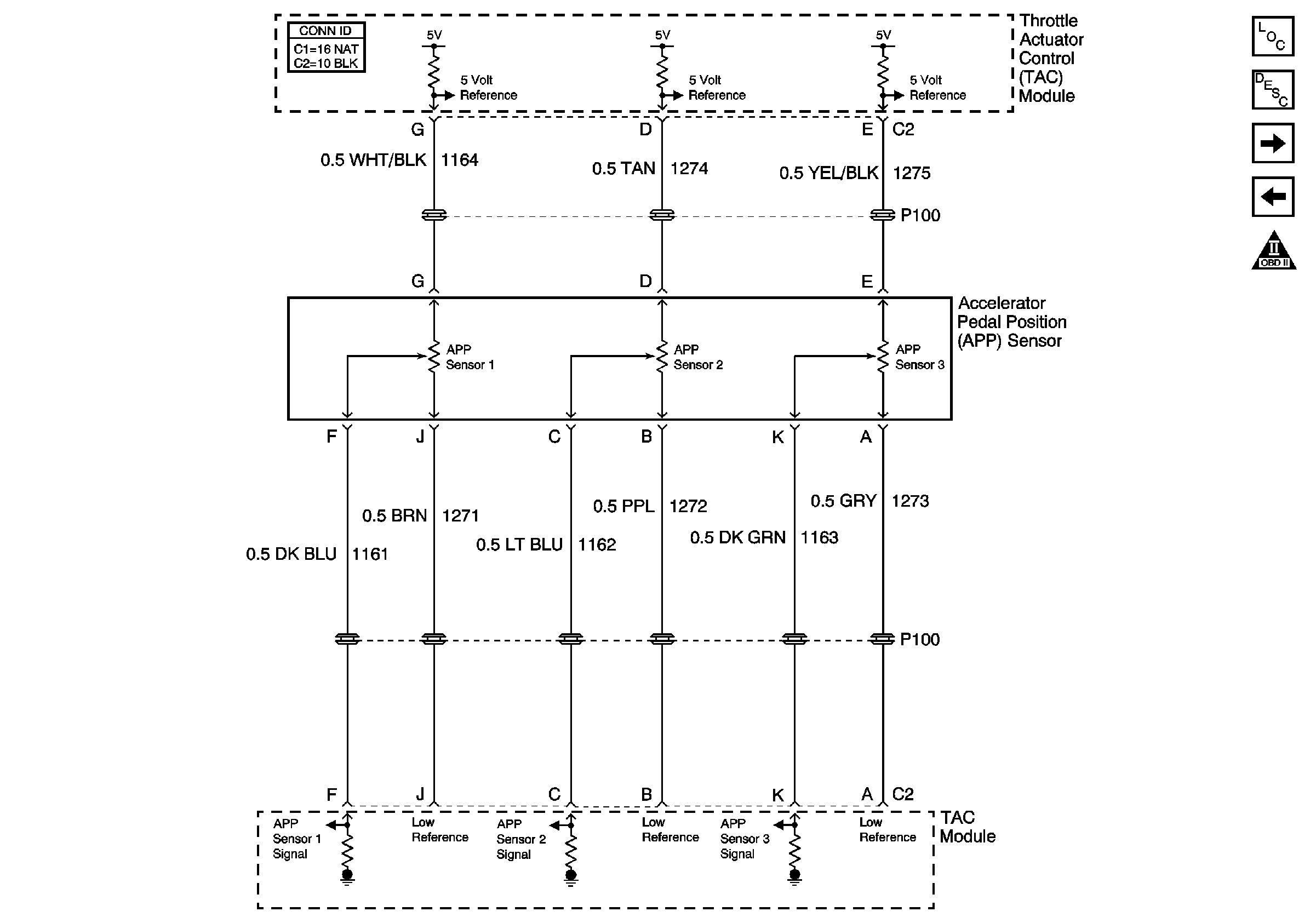
| Figure 7: |
Accelerator Pedal Position Sensor Circuits
|
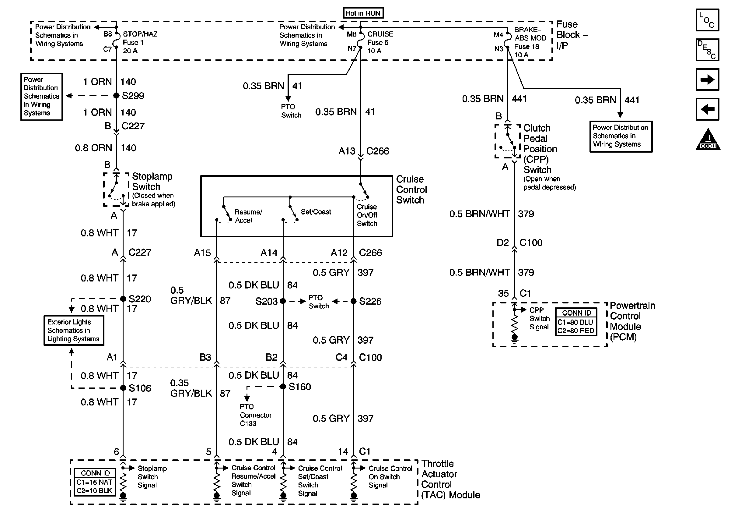
| Figure 8: |
TAC Cruise Control Inputs
|
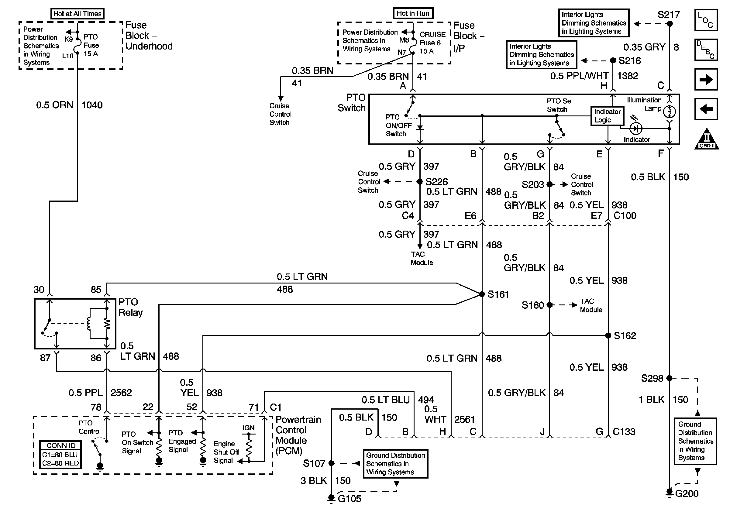
| Figure 9: |
PTO Control Provisions
|
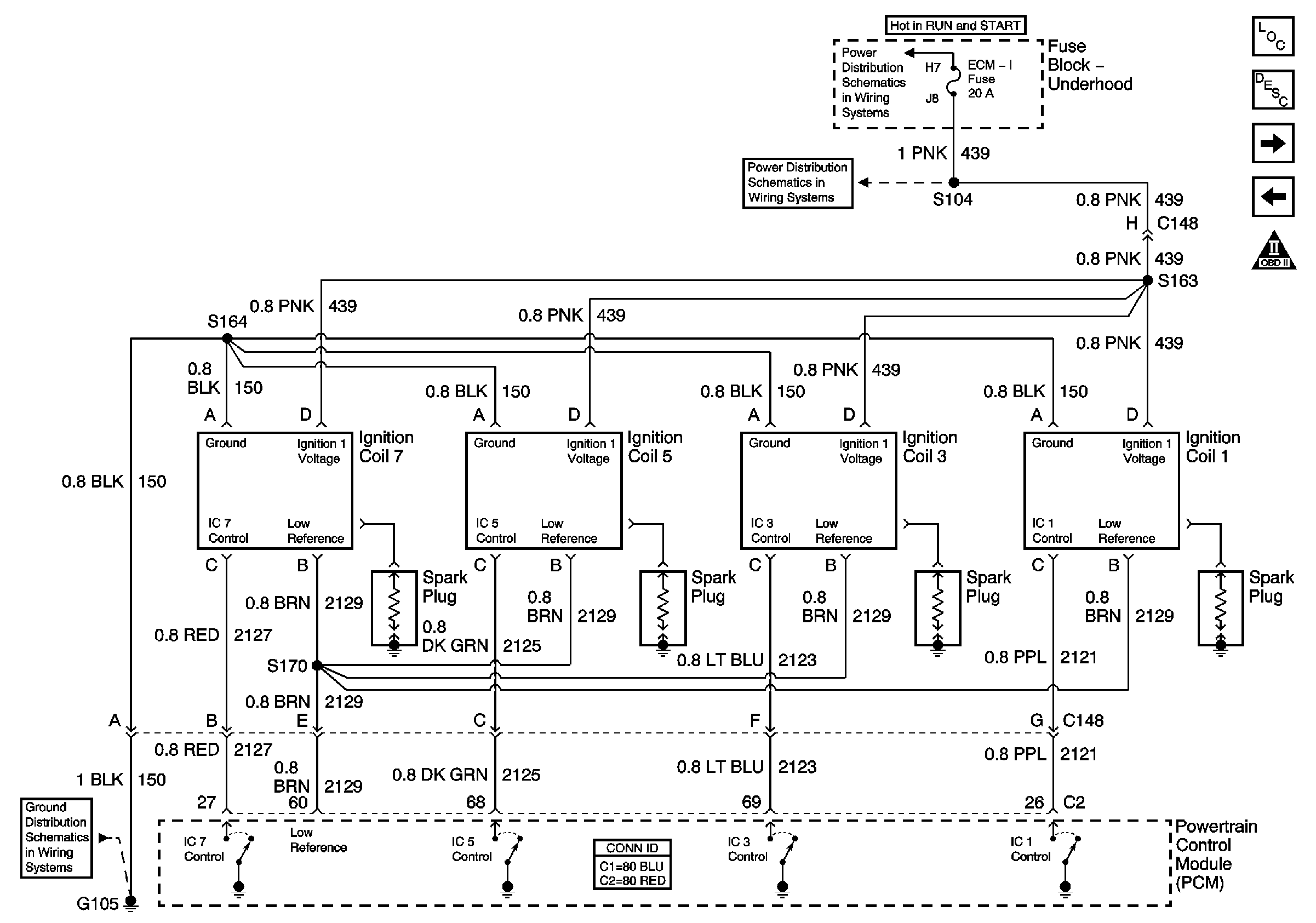
| Figure 10: |
Ignition Control, Bank 1 (Left Side)
|
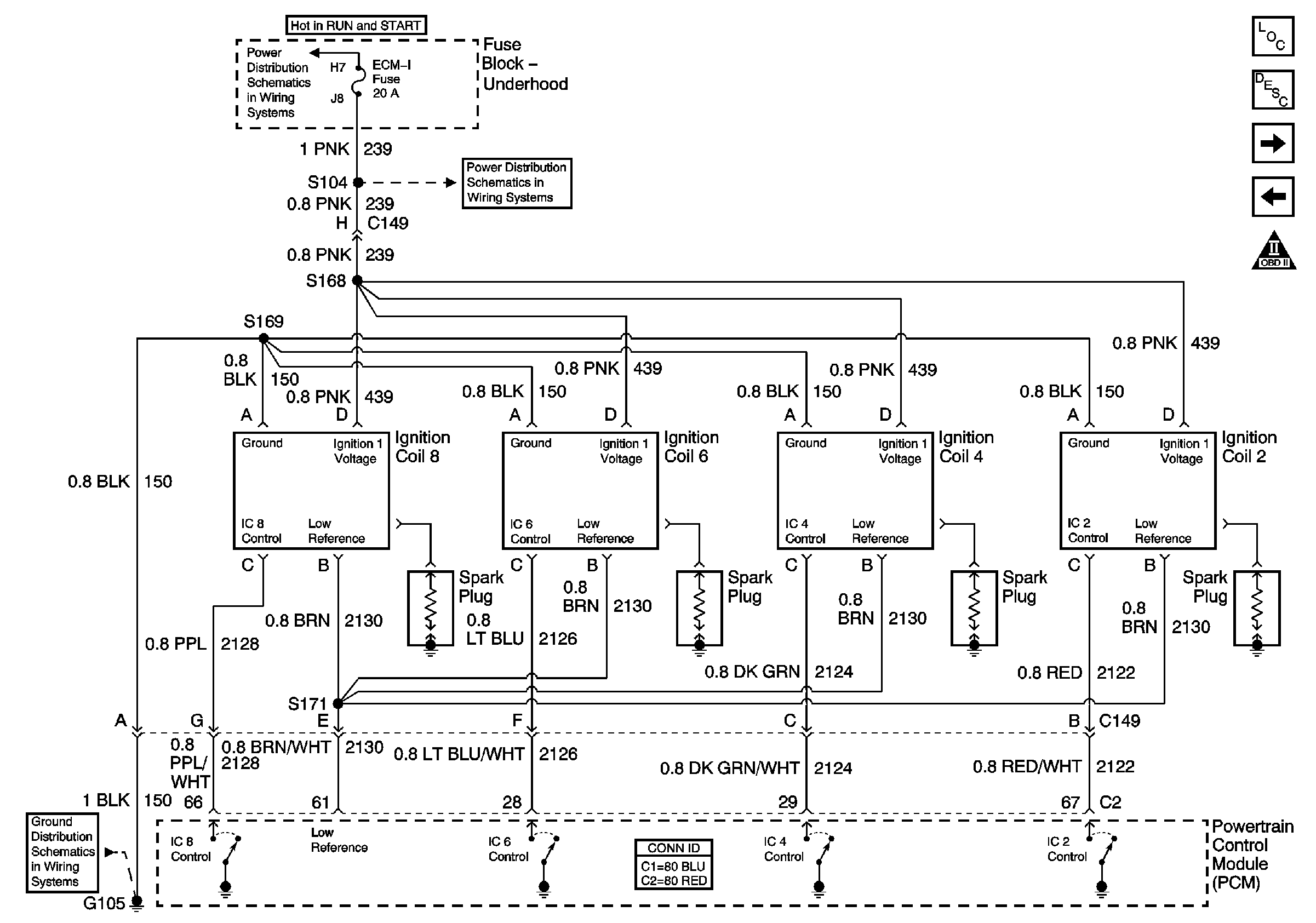
| Figure 11: |
Ignition Control, Bank 2 (Right Side)
|
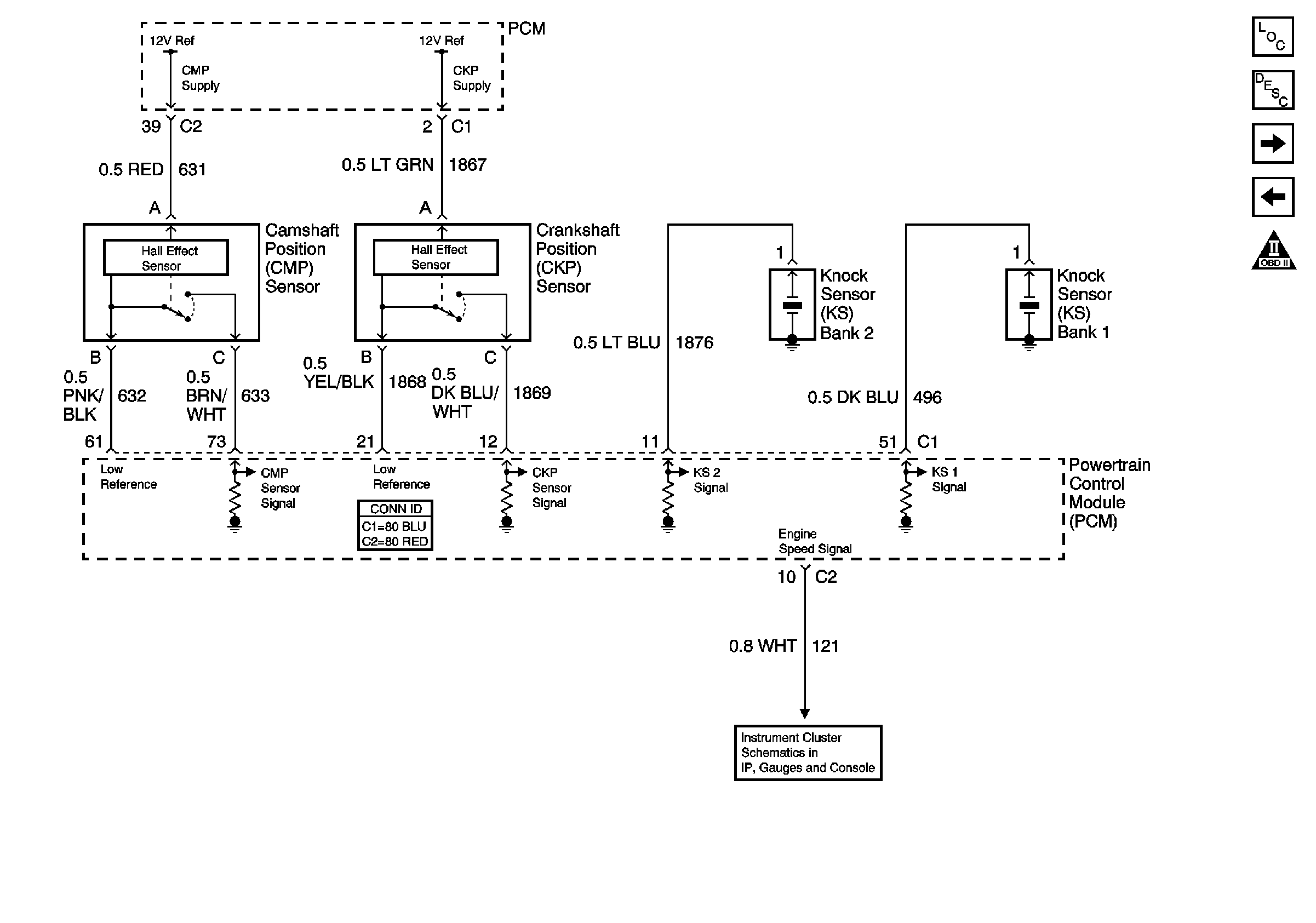
| Figure 12: |
CMP, CKP, and KS
|
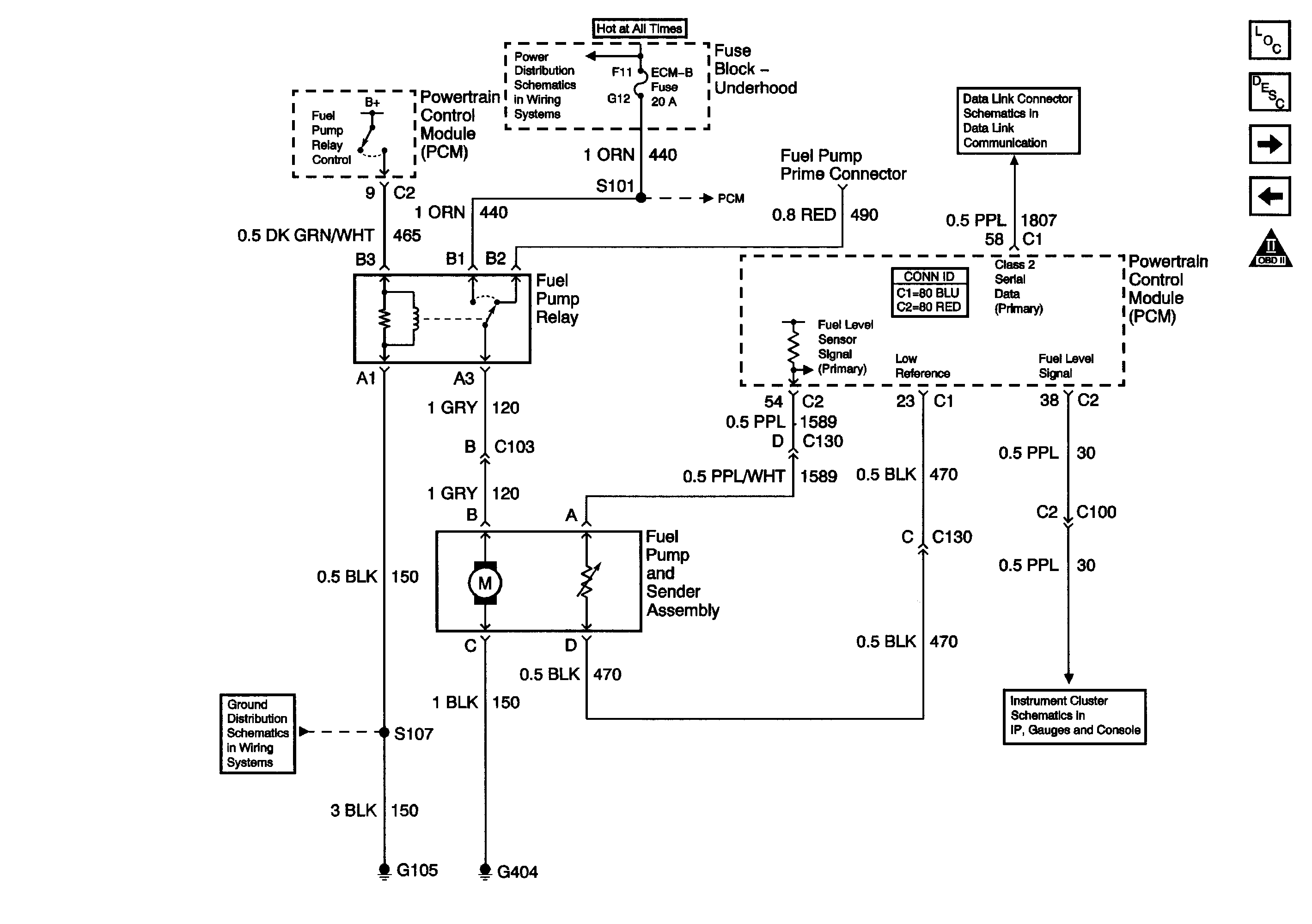
| Figure 13: |
Fuel Pump Controls, Single Tank
|
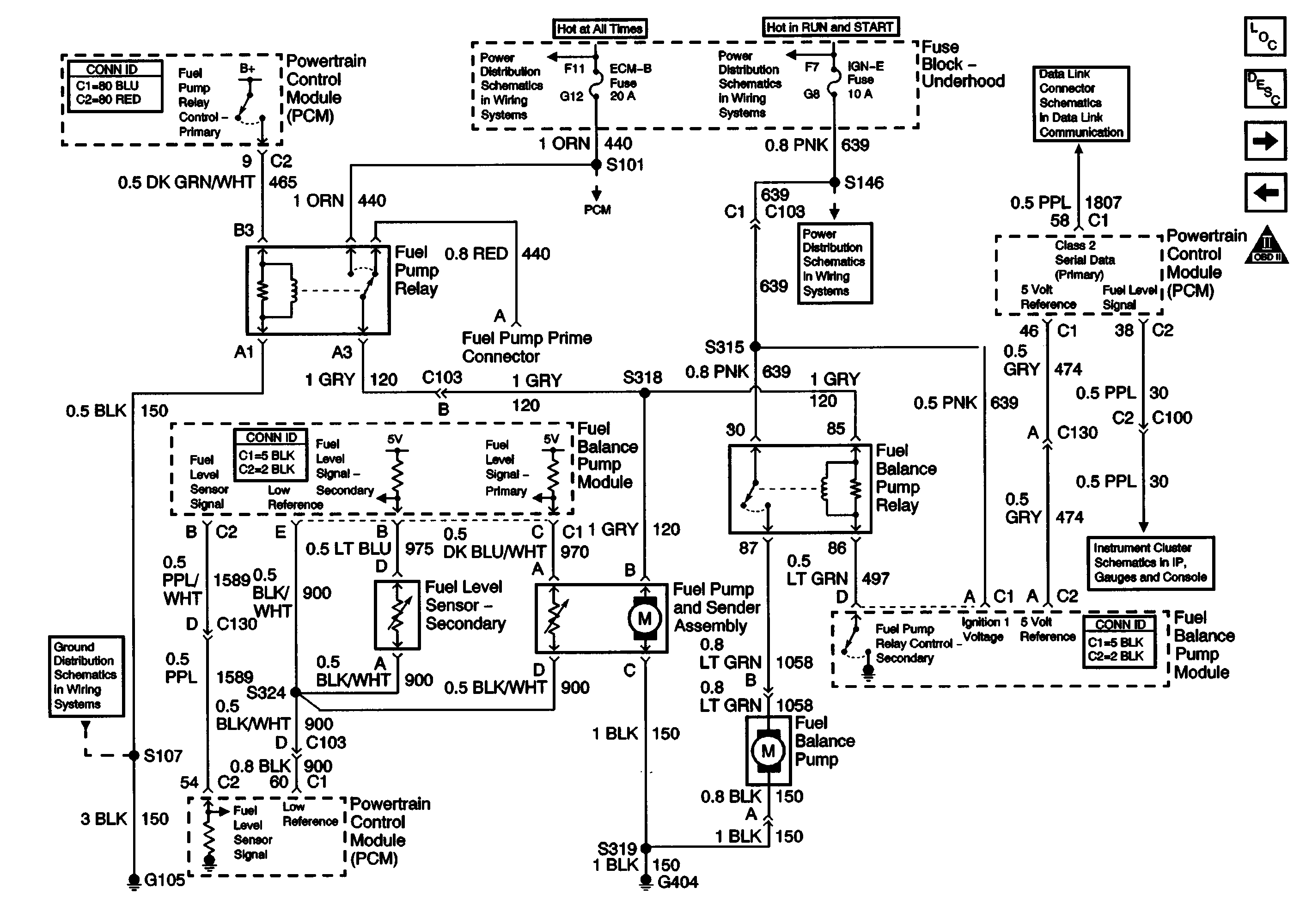
| Figure 14: |
Fuel Pump Controls, Dual Tanks
|
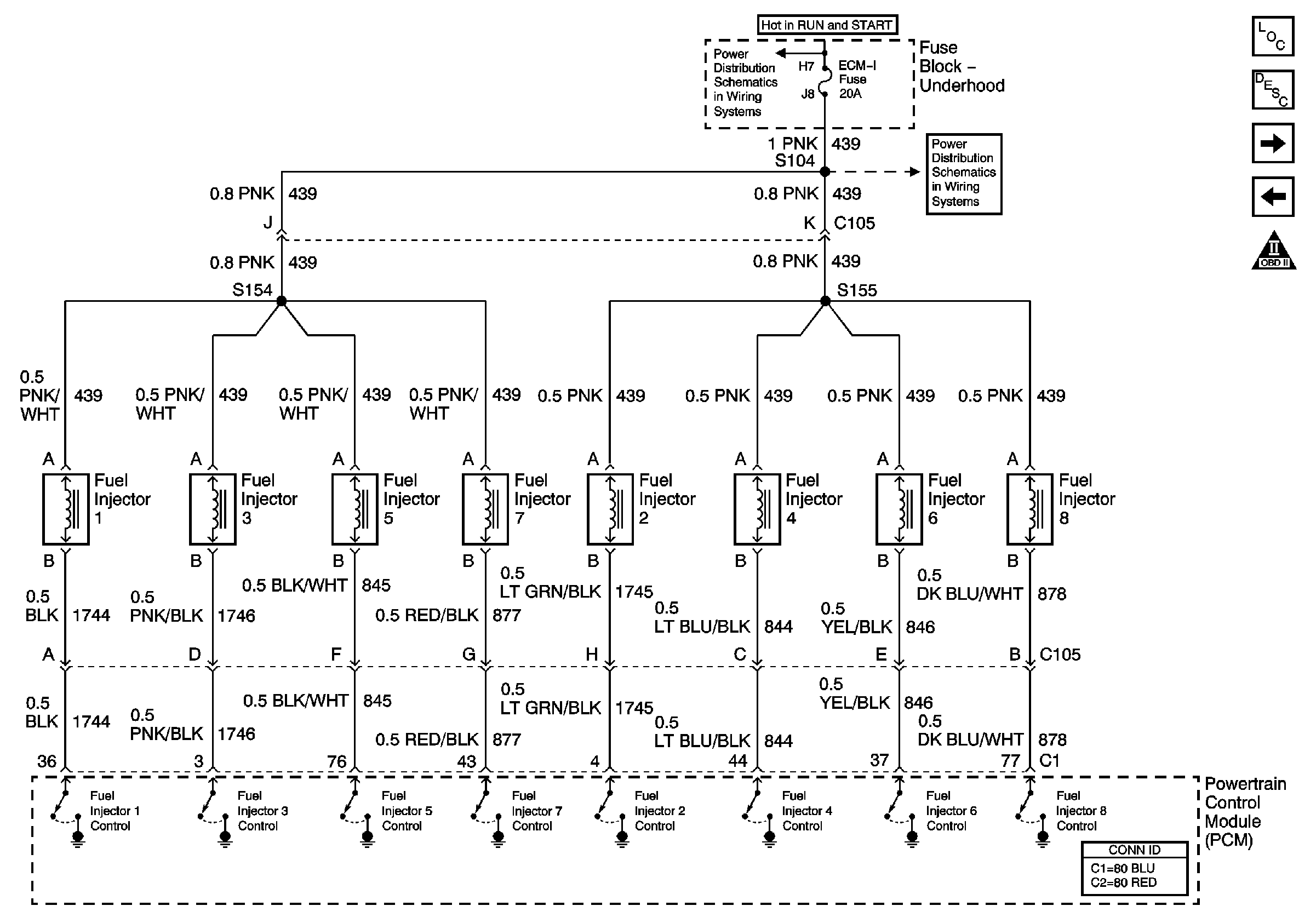
| Figure 15: |
Fuel Injector Controls
|
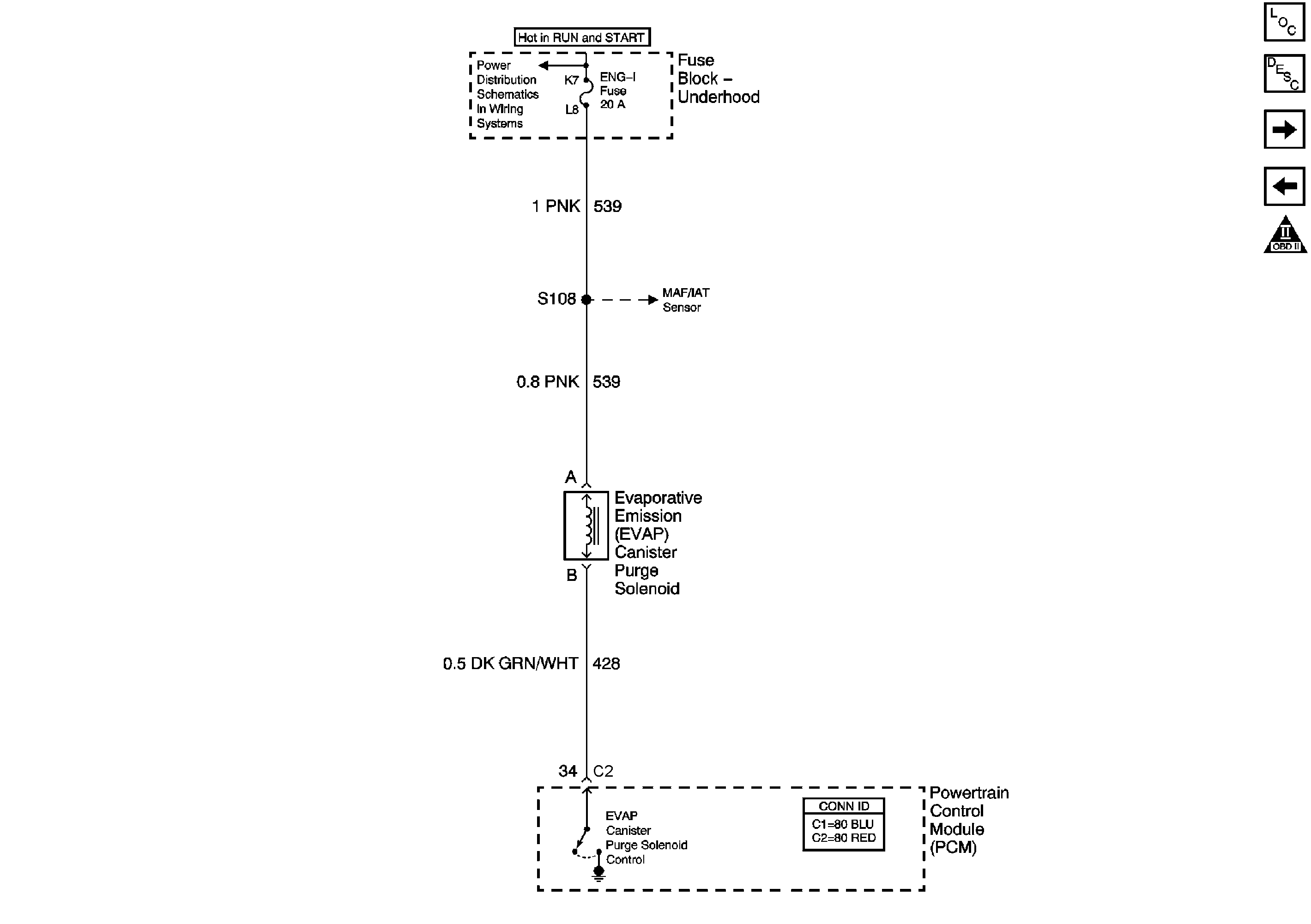
| Figure 16: |
EVAP and EGR
|
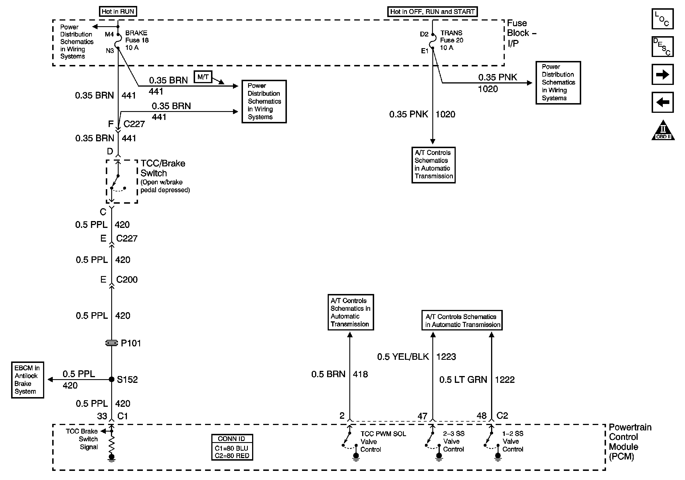
| Figure 17: |
A/T TCC/Stop Lamp Switch, Shift Solenoids
|
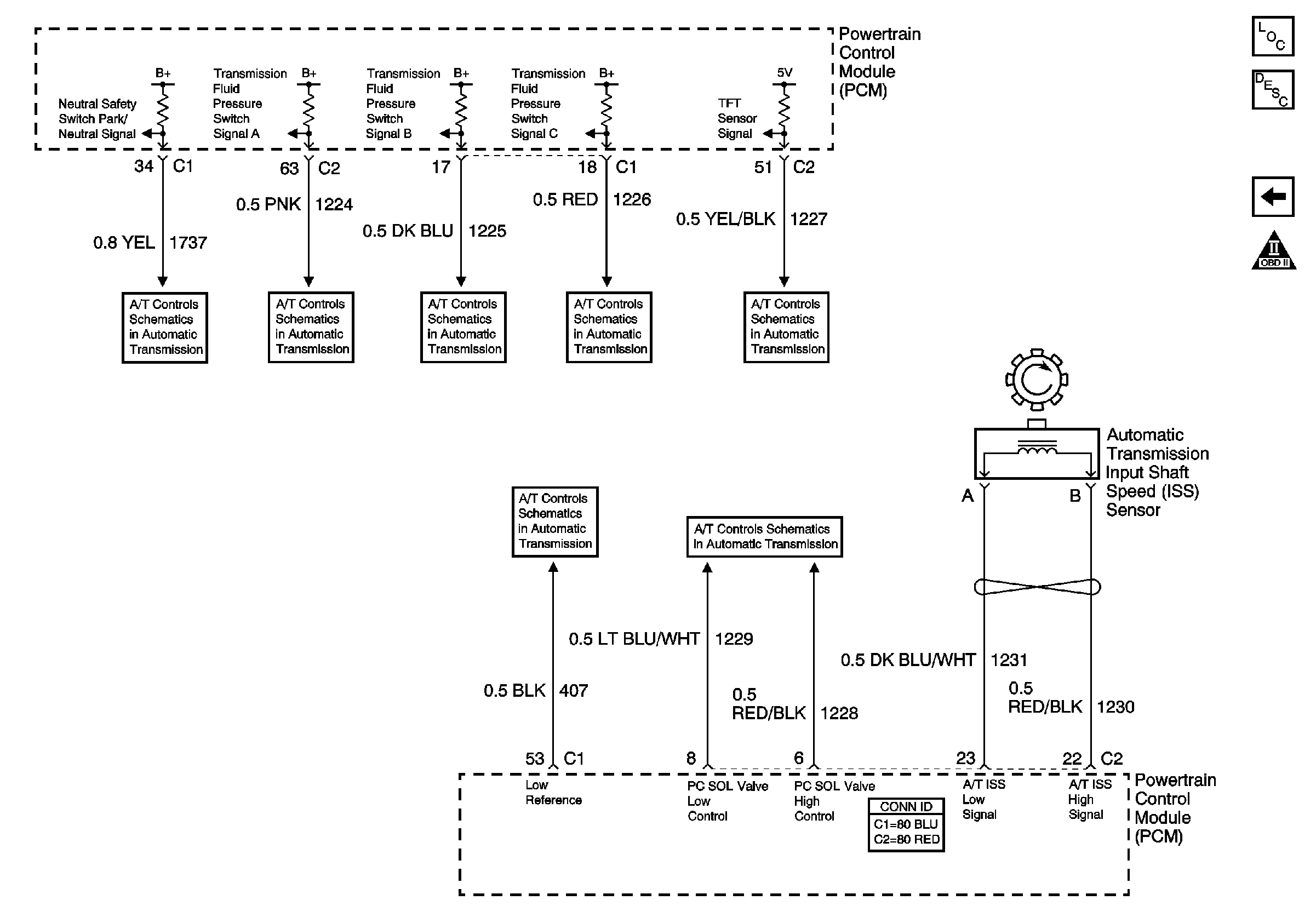
| Figure 18: |
A/T Internal Switches, TFT, PC Solenoid Valve
|


