The following components
are possible sources of driveline vibration:
| • | The transmission output shaft |
| • | The propeller shaft/s (driveshaft/s) |
The above components are either bolted or splined together. Therefore,
all of the components rotate at the same speed, vibrate at the same frequency
and have the same symptoms.
Driveline vibrations may relate either to the first or to the second
order of driveline rotation. Driveline vibrations are always related to the
speed of the vehicle. The vibration is often related to torque. If the vibration
is worse or only noticeable when accelerating, decelerating, or crowding
the throttle, then the vibration is related to the torque. The vibration
will always occur at the same speed. If a vibration is both torque and speed
sensitive, the driveline is the probable cause. Tire/wheel vibrations are
speed sensitive, but not torque sensitive.
First-Order Driveline Vibration Symptoms
The following symptoms may indicate first-order driveline vibration:
| • | The vibration is related to vehicle speed. |
| • | The vibration is torque sensitive. |
| • | A boom or moan noise is present. |
| • | The vibration occurs commonly above 72 km/h (45 mph),
but possibly as low as 48 km/h (30 mph). |
| • | The roughness or buzz vibration is felt in the seat, floor or
steering wheel. |
| • | The corresponding frequency on the EVA equals first-order driveline
rotation (25-60 Hz), depending on the speed of the vehicle and
the ratio of the axle. Refer to the worksheet in order to obtain the rotation
speed of the propeller shaft. |
Driveline Vibration Analysis
Once you identify a vibration that is related to the driveline, continue
testing in this service area. The following components are possible sources
of first-order driveline vibration:
| • | The transmission output shaft |
Locate the Source of Driveline Vibration with the EVA
Caution: Never run the vehicle faster than 112 km/h (70 mph) when
performing propeller shaft vibration or checking for balance. Stay clear of
rotating components and balance weights to avoid personal injury. Do not run
the vehicle on the hoist for extended periods of time to avoid engine or transmission
overheating. Do not step on the brake pedal with the brake drums
removed.
In order to pinpoint the source of vibration, reproduce
the vibration with the vehicle in the service stall. Then determine which
component is vibrating the most using the EVA and the following procedure:
- Raise the vehicle to curb height. Support the vehicle on a hoist
or on safety stands. Do not allow the axle to hang. Refer to Lifting and Jacking the Vehicle
in General
Information.
- Remove the rear tire/wheel assemblies. Refer to Wheel Removal (Single Wheels)
in Tires and Wheels.
- Remove the brake drums.
- Ensure that the propeller shaft is free of undercoating.
- Inspect the propeller shaft and U-joints for dents or damage.
- Start the engine.
- Place the transmission in gear.
- Run the vehicle at the speed which the vibration occurs.
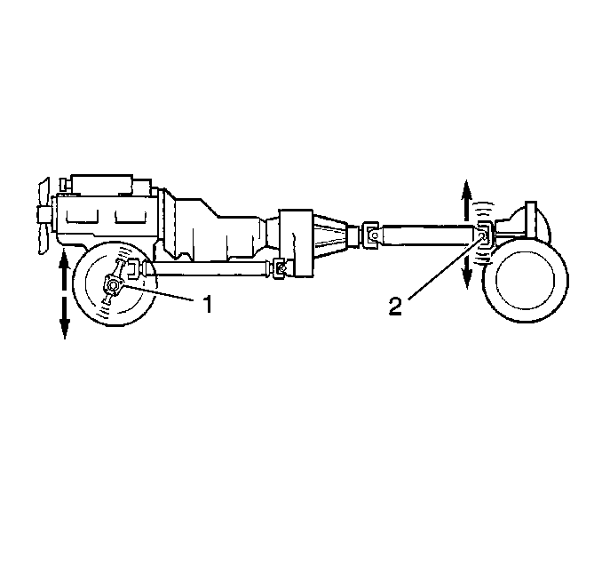
Hold the EVA sensor against the pinion nose and the transmission tailshaft
assembly in order to determine which end of the propeller shaft has the most
vibration. The end that has the most vibration will have a higher amplitude
on the EVA.
If the vehicle has a two-piece propeller shaft, inspect the center support
bearing.
If the transmission tailshaft vibrates, inspect the transmission crossmember
under the transmission mount. If the mount is secured properly, there should
be no vibration at the crossmember.
Runout and Balance Testing with the EVA
Ensure that the runout of the various driveline components are within
specifications. If the runouts are within specifications, strobe balance
the driveline. The EVA is able to simplify the balancing process. Use the
following procedure:
- Use the EVA in order to determine which end of the propeller shaft
has the most vibration.
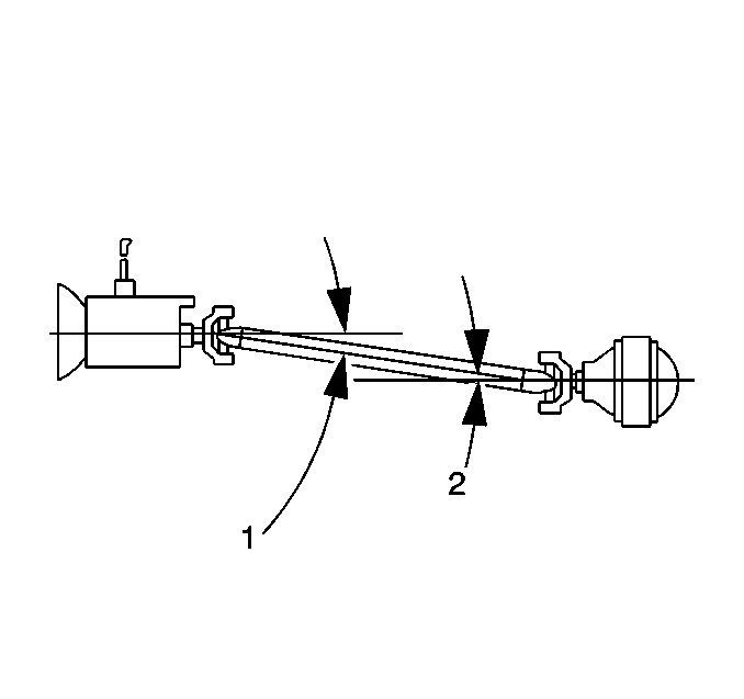
- Mark the end of the propeller shaft (1) that has the most vibration
at four points (2), 90 degrees apart. Number the marks 1 through 4.
- Mount the EVA sensor onto the bottom of the following components:
| • | The differential housing |
| • | The center bearing support (for two-part propeller shafts) |
| • | The transmission tailshaft assembly |
- Position the sensor as close to the propeller shaft as possible.
Ensure that the UP side of the sensor faces up. Ensure that the sensor is
horizontal.
Notice: Do not use cruise control to maintain vehicle speed.
- Start the engine.
- Turn off all engine accessories.
- Place the transmission in gear.
- Run the vehicle at the speed which causes the most vibration in
the propeller shaft.
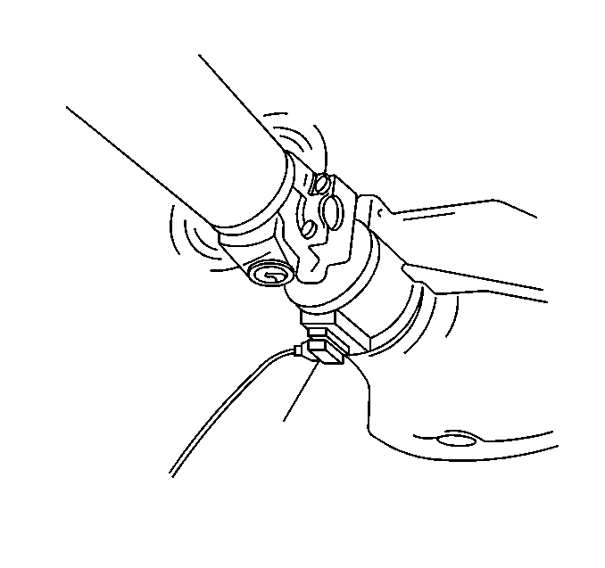
- Hook the timing light clip to the trigger wire.
- Plug the vibration sensor into Input A of the EVA. Input B does
not have strobe light capability.
- Verify that the predominant frequency on the EVA display matches
the frequency of the original vibration. Use the strobe light only if the
rotation speed of the propeller shaft is the predominant frequency.
- The EVA displays a series of questions in order to select the
correct filter. Press YES in order to select the desired filter. Ensure that
the frequency is in the middle of the filter range. Use the full range only
as a last resort.
- The EVA displays the test frequency, the amplitude and the filter
range. The driveline is balanced when the amplitude is near two. In some cases
a slightly higher amplitude will provide adequate balance.
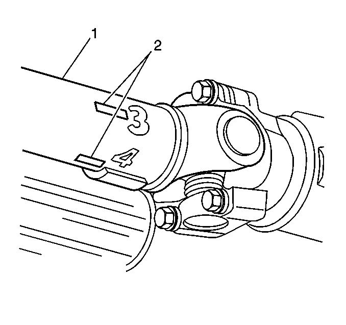
- Point the timing light at the propeller shaft. The strobe effect
will appear to freeze the propeller shaft. Note which of the numbered marks
is at the bottom of the propeller shaft (the 6 o'clock position).
This position is the light spot.
- Turn the engine off.
- Install a weight directly on the light spot.
- Start the engine.
- Run the vehicle at peak vibration speed.
- Strobe the propeller shaft again.
The propeller shaft is balanced if the strobe image is erratic and the
amplitude is near two.
The propeller shaft is not balanced if one of the following conditions
exist:
| • | The weight and the original light spot are at the 6 o'clock
position -- This condition means that there is not enough weight on the
propeller shaft. |
| | In order to correct the balance, add a second weight next to the first
weight. Inspect the balance again using the strobe light. |

| • | If the weights are now between 90 and 180 degrees off (between
the 9 and the 3 o'clock positions) there is too much weight. In order
to correct the balance, split the two weights equally on either side of the
original light spot. Splitting the weight will produce a total weight between
one and two weights. |
| | Inspect the balance again using the strobe light. Adjust the weights
as necessary. |
| • | The weight and original light spot are 90 to 180 degrees
off (between the 9 and the 3 o'clock positions) -- This condition
means that one weight is too much. |
| | In order to correct the balance, split the two weights equally on either
side of the original light spot. in order to produce a total weight less than
one (between 120 and 180 degrees apart). |
| | Inspect the balance again using the strobe light. Adjust the weights
as necessary. |
| • | The weight and the original light spot are within 180 degrees
of the 6 o'clock position. |
| | Move weight towards the 6 o'clock position. Inspect the balance
again using the strobe light. Adjust the weight as necessary. Refer to the
previous two conditions. |
If the shaft will not balance using two weights, then place a third
weight on the light spot. Split the first two weights in order to produce
a total weight between two and three weights.
If three weights fail to balance the driveline, replace the propeller
shaft.
When the propeller shaft balances, road test the vehicle in order to
verify that the vibration is eliminated.
First-Order Driveline Vibration Analysis (Torque Sensitive)
If the vehicle has a vibration that is equal to first-order driveline
rotation, and the vibration is not present when testing the vehicle in the
stall, then internal rear axle components are the probable cause of the vibration.
Internal rear axle components are also the probable cause of the vibration
if you were able to correct the vibration in the stall, but the vibration
returned during the road test. Internal rear axle vibrations may be aggravated
by the load of the vehicle working against the ring and pinion gear seat.
Since the propeller shaft and the pinion gear are bolted together through
the pinion flange, the propeller shaft and the pinion gear operate at the
same speed. Vibration in the pinion gear will therefore have the same frequency
and symptoms as the propeller shaft.
In order to isolate the vibration to the pinion gear, use the following
procedure:
- Raise the vehicle to curb height. Support the vehicle on a hoist
or on safety stands. Refer to Lifting and Jacking the Vehicle
in General Information.
- Remove the tire/wheel assemblies. Refer to Wheel Removal (Single Wheels)
in Tires and Wheels.
- Remove the brake drums. Refer to Brake Drum Replacement
in Drum Brakes.
- Touch the pinion nose, or hold the EVA vibration sensor up to
the pinion nose.
- Use another technician in order to accelerate and decelerate the
vehicle through the speed range at which the vibration was noticed during
the road test.
Example
| • | If the vibration was originally noticed at 88 km/h (55 mph),
accelerate from 72 km/h (45 mph) to 107 km/h (65 mph).
Then decelerate from 107 km/h (65 mph) back to 72 km/h
(45 mph). |
| • | Repeat the above step and note whether or not the pinion nose
vibrates under load during acceleration and/or deceleration. |
If the vibration does not occur during the above procedure, install
the brake drums and the tire/wheel assemblies. The brake drums and tire/wheel
assemblies will add additional load on the system. Then repeat the above
test.
Ensure that both axle shafts rotate at the same speed. The differential
may mask a vibration when one tire is spinning faster than the other tire.
Adjust the brakes in order to correct unequal tire rotation speed.
If you are unable to reproduce the vibration in the stall, apply the
brake lightly in order to load the system further. Maintain the vehicle speed
at which the vibration was noticed. Do not overheat the brakes.
If the pinion nose vibrates under acceleration and/or deceleration,
and the other driveline components are eliminated as the cause of the vibration,
then one of the following conditions may cause the vibration:
| • | A high spot on the pinion gear |
| • | A cocked pinion bearing |
| • | An improper axle housing bore |
Anything that effects the pinion gear and how the pinion gear contacts
the rotating ring gear may contribute to a first-order, torque-sensitive driveline
vibration. The only way to correct the condition is to replace the faulty
components. In most cases, the ring and pinion gear set and the related bearings
must be replaced. In some case, however, the axle housing must be replaced.
Complete a close-up visual inspection for damage or unusual wear in order
to measure or identify the specific faulty component.
It is possible to isolate an internal axle vibration. Install a known
good axle assembly from a stock unit. Verify that the known good axle assembly
does not have a vibration problem.
Once you correct the internal axle problem, road test the vehicle. Inspect
the vehicle for vibration. Balance the driveline as necessary in order to
eliminate any remaining vibration.
Second-Order Driveline Vibration Theory
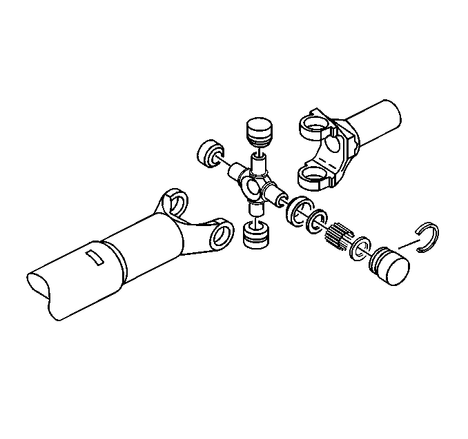
A faulty universal joint
(U-joint) may cause a vibration that occurs twice for each rotation of the
propeller shaft. This type of vibration is called a second-order vibration.
Second-order driveline vibrations are independent of runout or balance
of a driveline component.
The following description of basic U-joint theory will help you to understand
where second-order driveline vibrations originate and why they occur.
| • | As the propeller shaft rotates, the U-joints speed up and slow
down twice for each rotation of the propeller shaft. |
| • | The acceleration and deceleration of the U-joints is not visible.
If there is vibration in the U-joints, the acceleration and deceleration will
be audible and tactile. |
| • | Compare the U-joint in a vehicle to a universal-type socket. When
a universal-type socket is used to tighten a bolt, the socket will bind and
release as the socket turns toward 90 degrees. The bind and release
occurs twice for each revolution of the socket. |
| • | The U-joint in a vehicle works in the same way as the universal-type
socket. The bind and release effect is directly proportional to the angle
that the U-joint operates: the greater the angle, the greater the effect. |
| • | Because the transmission output speed is constant, the binding
and releasing of the U-joints is better described as an acceleration and deceleration
which occurs twice for each revolution of the propeller shaft. |
| • | If the propeller shaft is running slowly, the accelerating and
decelerating effect is visible. The acceleration and deceleration may create
a vibration due to the fluctuations in force that are generated at high speeds. |
Canceled Out Driveline Angles