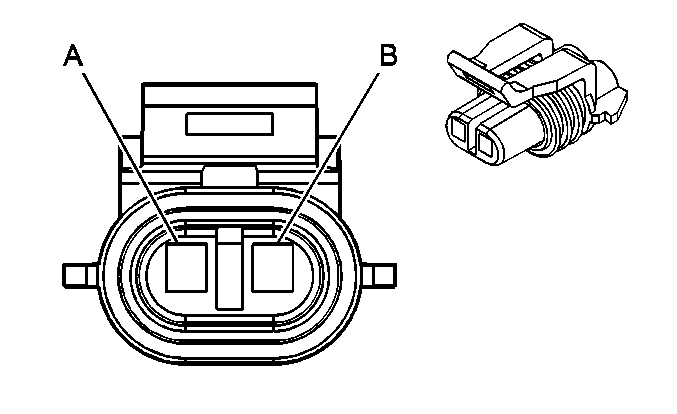
| Table 1: | Auxiliary Battery Relay |
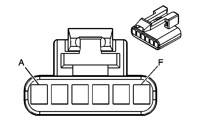
| Table 2: | Clutch Start Switch |
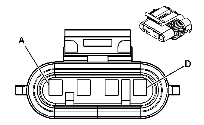
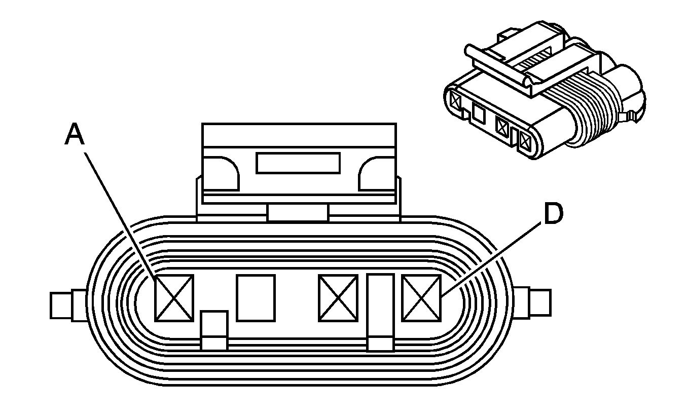
| Table 3: | Generator - Gas (w/ SBA) |
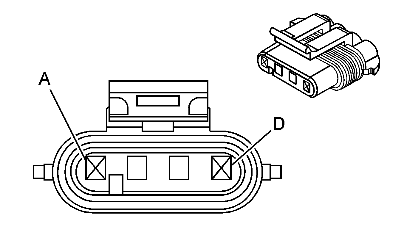
| Table 4: | Generator - Gas (w/o SBA) |
| Table 5: | Generator - Left - Diesel |
| Table 6: | Generator - Right - Diesel |
| |||||||
|---|---|---|---|---|---|---|---|
Connector Part Information |
| ||||||
Pin | Wire Color | Circuit No. | Function | ||||
A | BRN | 241 | Ignition 3 Voltage | ||||
B | BLK | 550 | Ground | ||||
| |||||||
|---|---|---|---|---|---|---|---|
Connector Part Information |
| ||||||
Pin | Wire Color | Circuit No. | Function | ||||
A | PPL | 420 | Cruise Control Release Signal | ||||
B | BRN/WHT | 379 | CPP Switch Signal | ||||
C | PNK | 639 | Ignition 1 Voltage | ||||
D | DK GRN | 1433 | Clutch Start Switch Signal | ||||
E | BRN | 441 | Ignition 3 Voltage | ||||
F | GRY | 48 | CPP Switch Signal | ||||
| |||||||
|---|---|---|---|---|---|---|---|
Connector Part Information |
| ||||||
Pin | Wire Color | Circuit No. | Function | ||||
A | DK BLU | 5668 | Engine On Signal | ||||
B | BRN | 25 | Charge Indicator Control | ||||
C | GRY | 23 | Generator Field Duty Cycle Signal | ||||
D | -- | -- | Not Used | ||||
| |||||||
|---|---|---|---|---|---|---|---|
Connector Part Information |
| ||||||
Pin | Wire Color | Circuit No. | Function | ||||
B | BRN | 25 | Charge Indicator Control | ||||
C | GRY | 23 | Generator Field Duty Cycle Signal | ||||

| |||||||
|---|---|---|---|---|---|---|---|
Connector Part Information |
| ||||||
Pin | Wire Color | Circuit No. | Function | ||||
B | BRN | 25 | Charge Indicator Control | ||||
C | GRY | 23 | Generator Field Duty Cycle Signal | ||||
| |||||||
|---|---|---|---|---|---|---|---|
Connector Part Information |
| ||||||
Pin | Wire Color | Circuit No. | Function | ||||
B | BRN | 2524 | Generator 2 Turn On Signal | ||||
