Removal Procedure
- Disconnect the negative battery cable. Refer to Battery Negative Cable Disconnection and Connection in Engine Electrical.
- Remove the air cleaner. Refer to Air Cleaner Assembly Replacement .
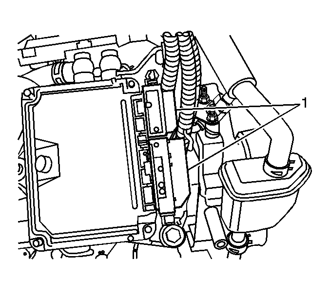
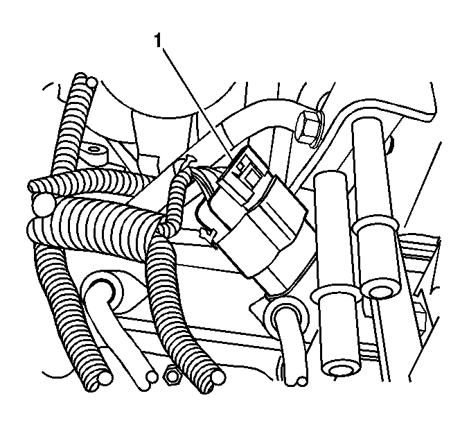
- Disconnect the fuel injection control module electrical connectors (1).
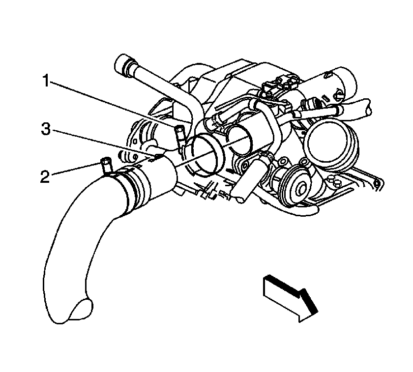
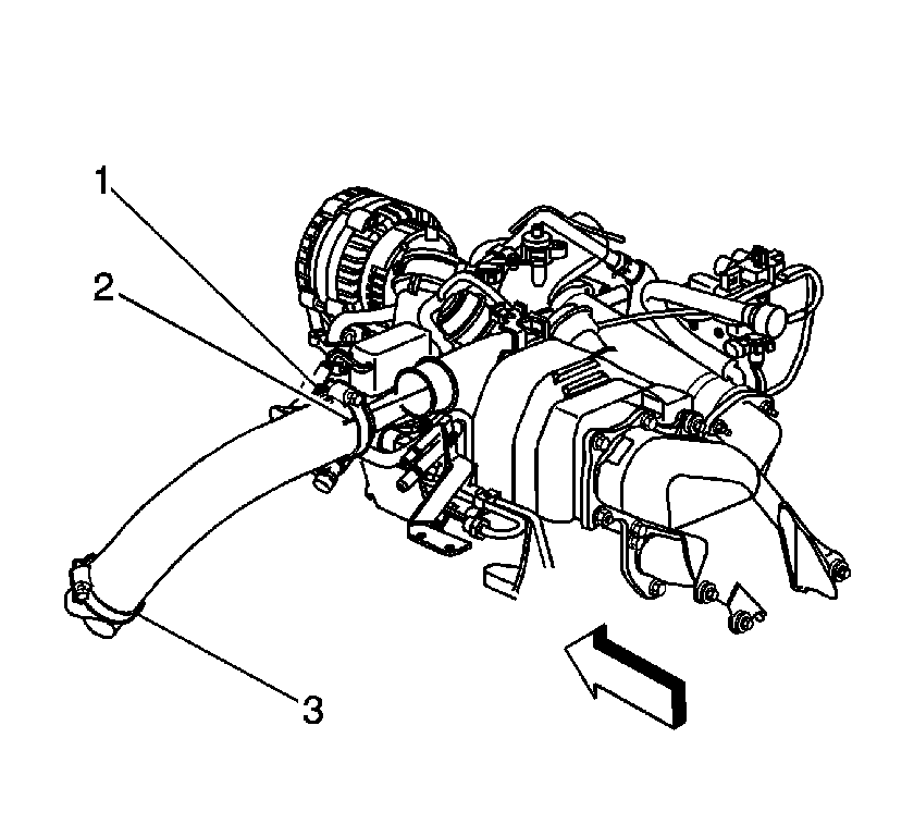
- Loosen the charged air cooler outlet duct clamp (1).
- Remove the charged air cooler outlet duct.
- Disconnect the following electrical connectors:
- Disconnect the right rear fuel injector electrical connector (1).
- Disconnect the exhaust gas recirculation (EGR) valve solenoid electrical connector (1).
- Disconnect the EGR valve vent solenoid electrical connector (1).
- Disconnect the EGR valve vacuum sensor electrical connector (1).
- Disconnect the EGR throttle valve solenoid electrical connector.
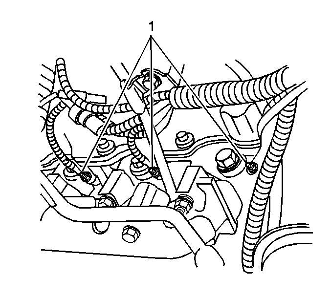
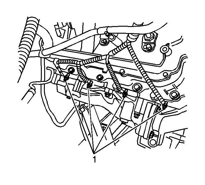
- Remove the right side glow plug electrical nuts.
- Remove the right side engine harness from the glow plug (1).
- Disconnect the right front fuel injector electrical connector (1).
- Disconnect the turbocharger boost sensor electrical connector (1).
- Remove the sight shield hold-down bolt and bracket (1).
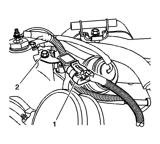
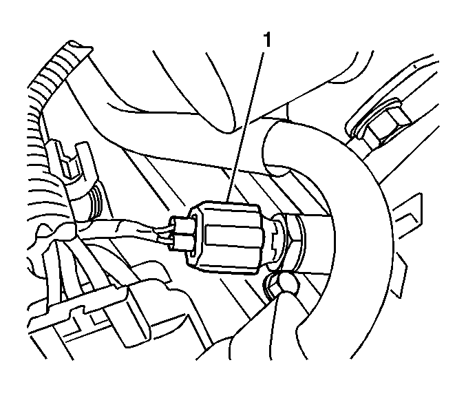
- Disconnect the engine coolant temperature (ECT) sensor electrical connector (1).
- Reposition the turbocharger water inlet hose clamp.
- Remove the turbocharger water inlet hose.
- Remove the turbocharger coolant bypass valve.
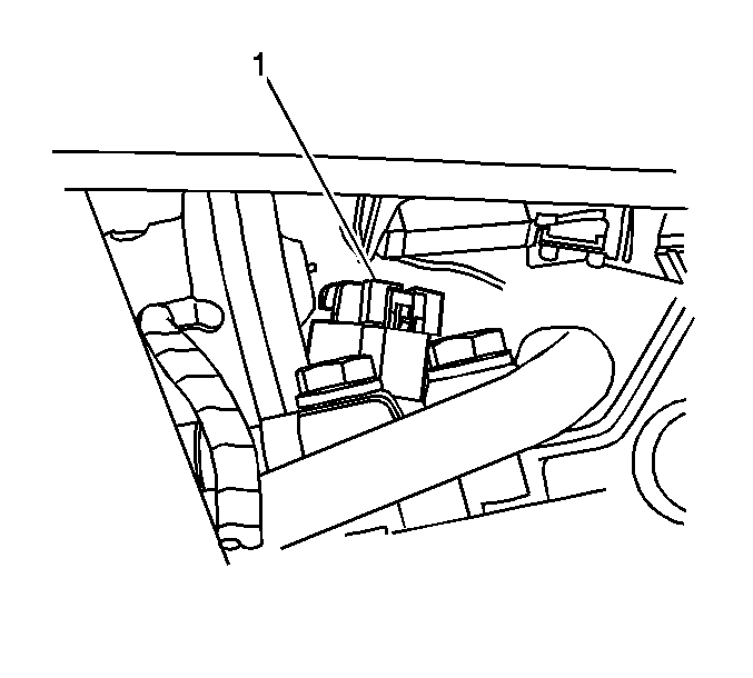
- Remove the glow plug relay. Refer to Glow Plug Relay Replacement .
- Disconnect the engine harness electrical connectors.
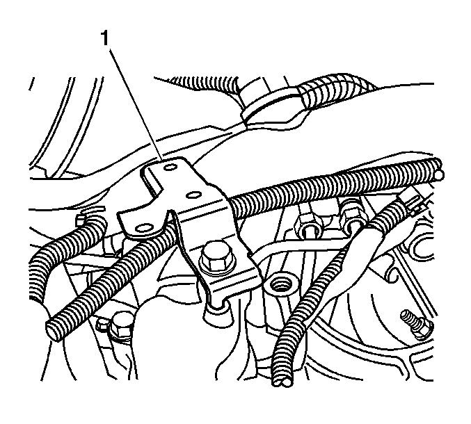
- Remove the bulk connector bolts from the bracket (1).
- Loosen the charged air cooler inlet duct to turbocharger clamp (1).
- Remove the charged air cooler inlet duct from the turbocharger.
- Reposition the positive crankcase ventilation (PCV) hose clamp.
- Remove the PCV hose from the left valve cover.
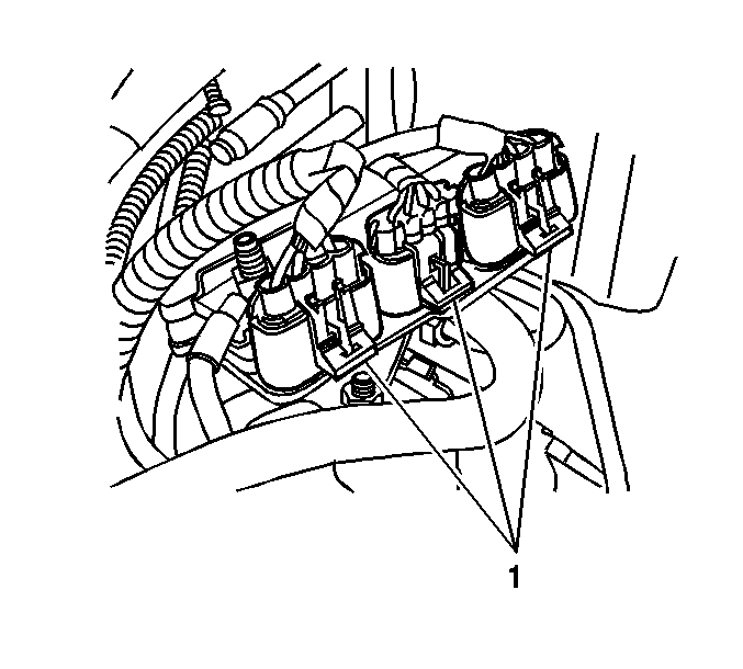
- Disconnect the left front fuel injector electrical connector (1).
- Disconnect the left rear fuel injector electrical connector (1).
- Disconnect the fuel rail temperature sensor electrical connector (1).
- Disconnect the glow plug controller electrical connectors (1).
- Remove the fuel pipe retainer nut at the valve cover.
- Remove the fuel pipe retainer (2).
- Remove the left front wheelhouse panel. Refer to Wheelhouse Panel Replacement in Body Front End.
- Remove the left side glow plug electrical nuts.
- Remove the left side engine harness from the glow plugs (1).
- Disconnect the oil level electrical connector (1).
- Disconnect the barometric pressure (BARO) sensor electrical connector (1).
- Disconnect the fuel rail pressure sensor electrical connector (1).
- Raise and suitably support the vehicle. Refer to Lifting and Jacking the Vehicle in General Information.
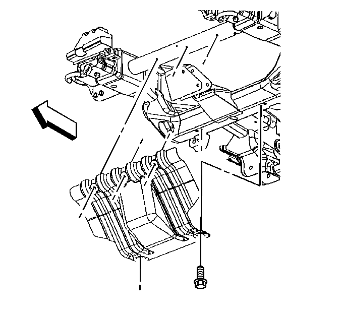
- Remove the engine shield bolts and shield.
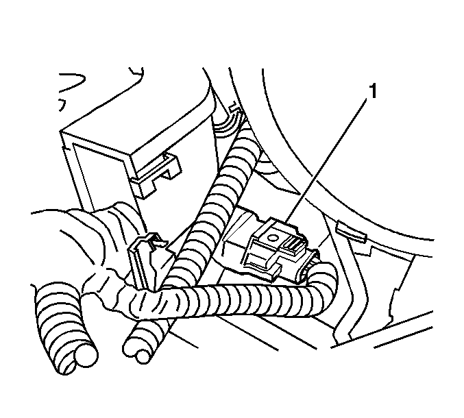
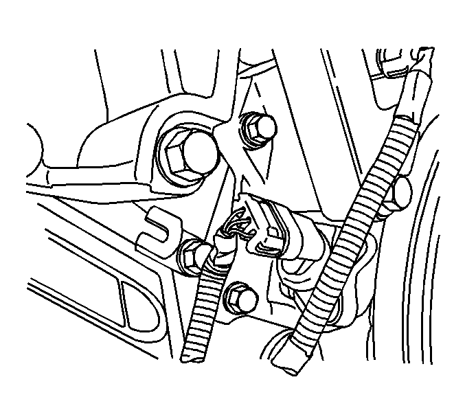
- Disconnect the crankshaft position (CKP) sensor electrical connector.
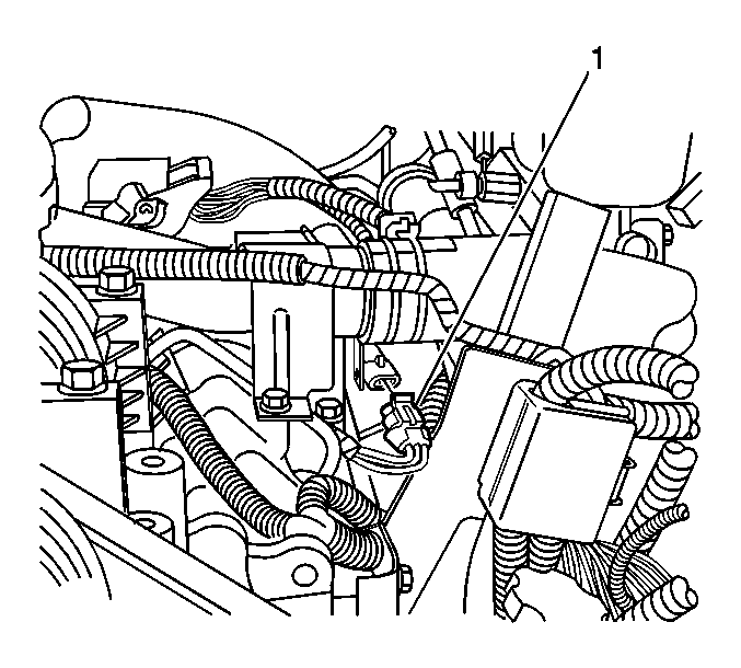
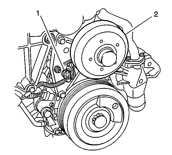
- Disconnect the camshaft position (CMP) sensor electrical connector (1).
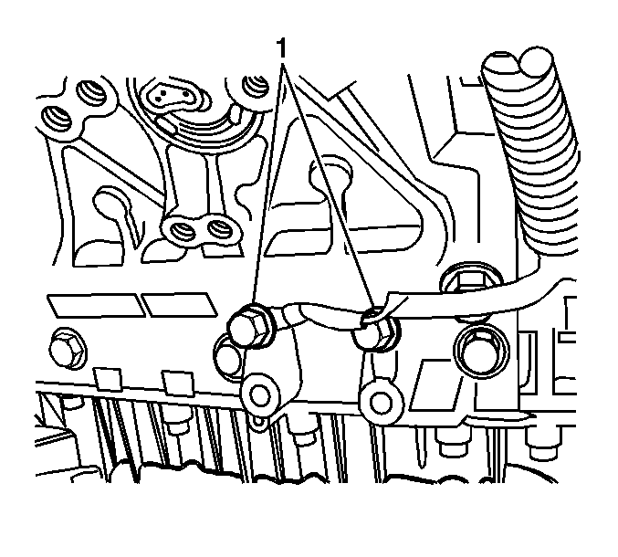
- Remove the engine harness ground bolts (1).
- Lower the vehicle.
- Unroute and lift up the engine wiring harness for access to fuel pressure regulator.
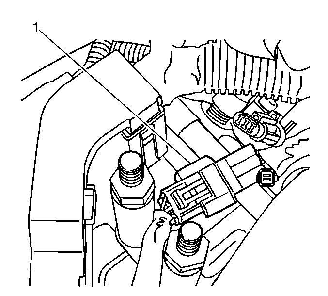
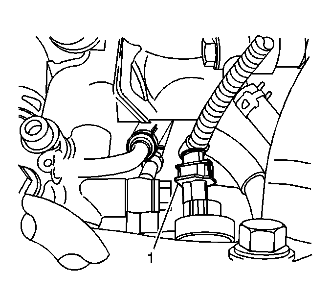
- Disconnect the fuel pressure regulator electrical connector (1).
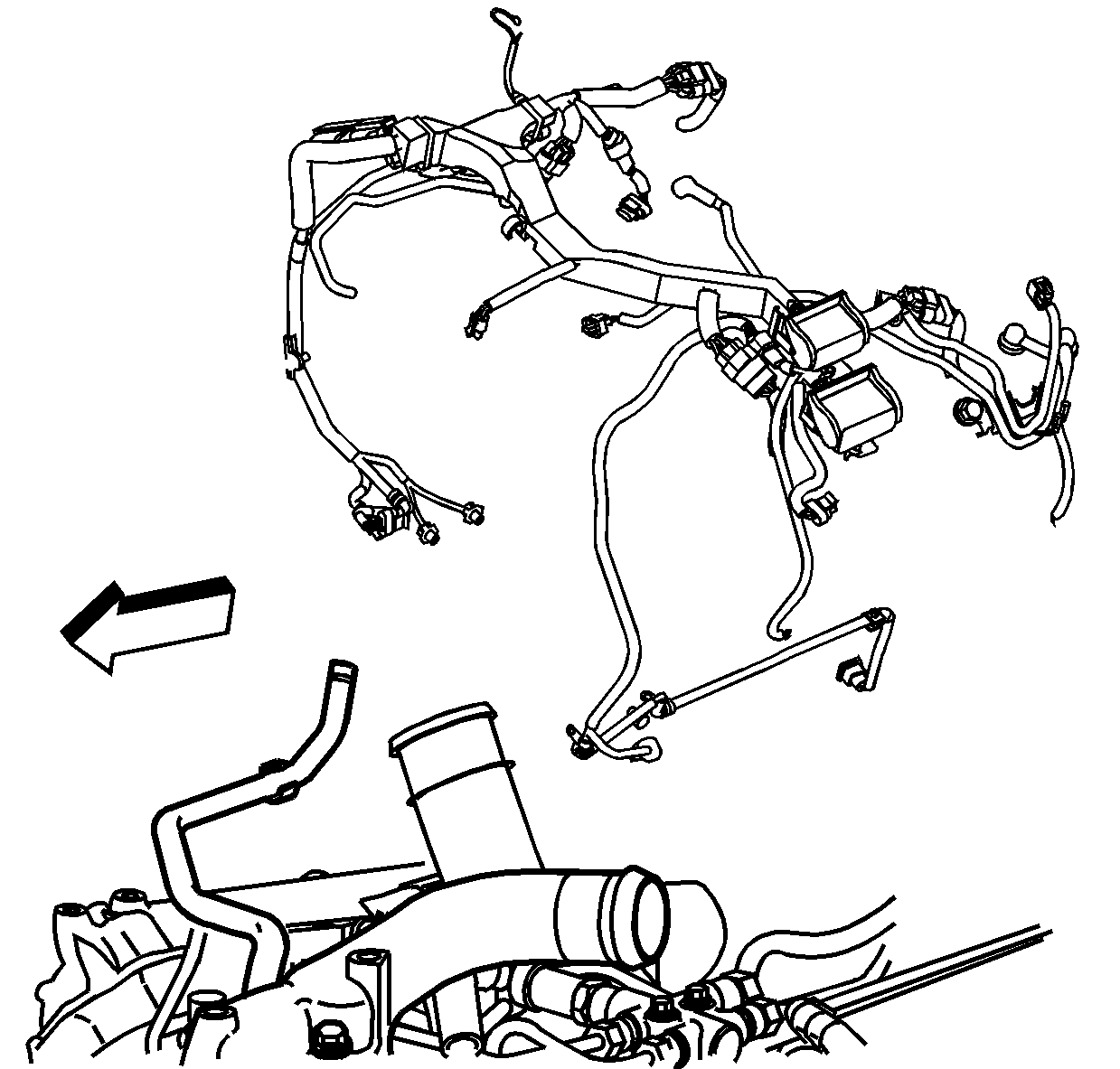
- Remove the engine wiring harness.
Important: Do not use a screwdriver or other tool to pry the hose loose. The hose can be torn or damaged. Loosen the hose by twisting.
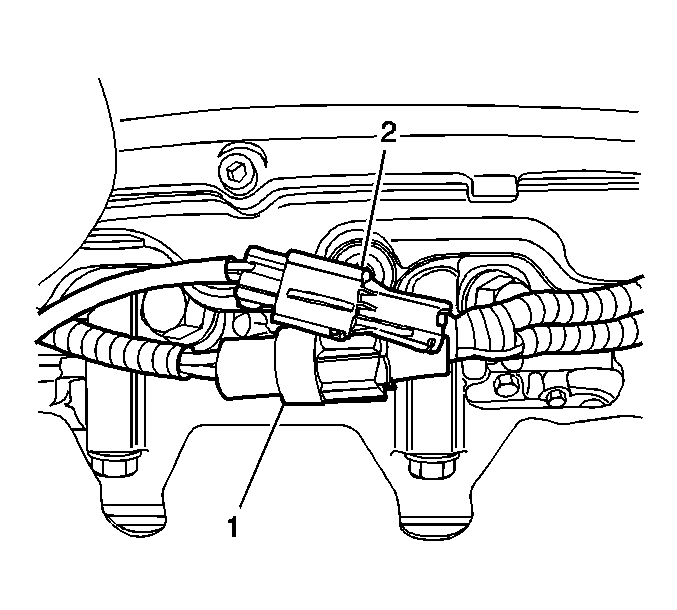
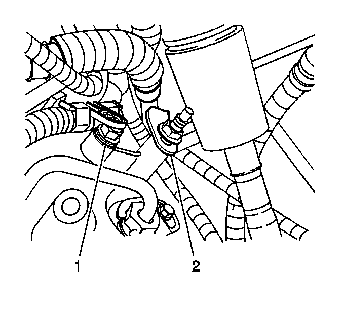
| • | Water-in-fuel sensor (1) |
| • | Fuel heater (2) |
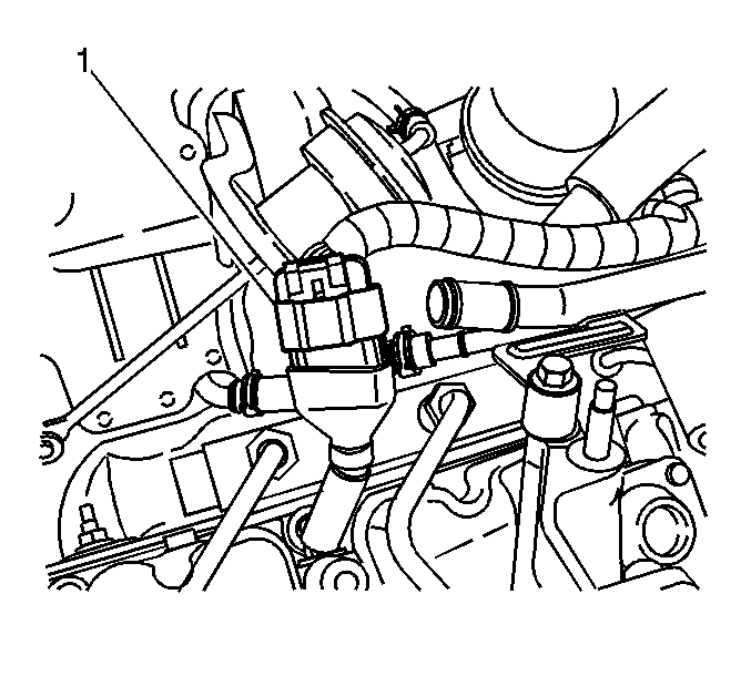
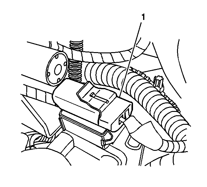
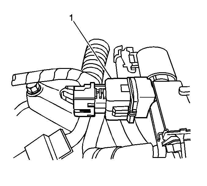
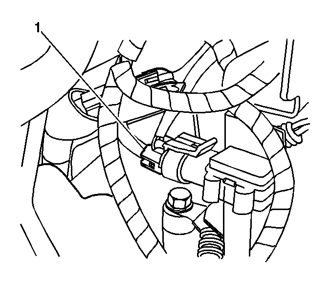
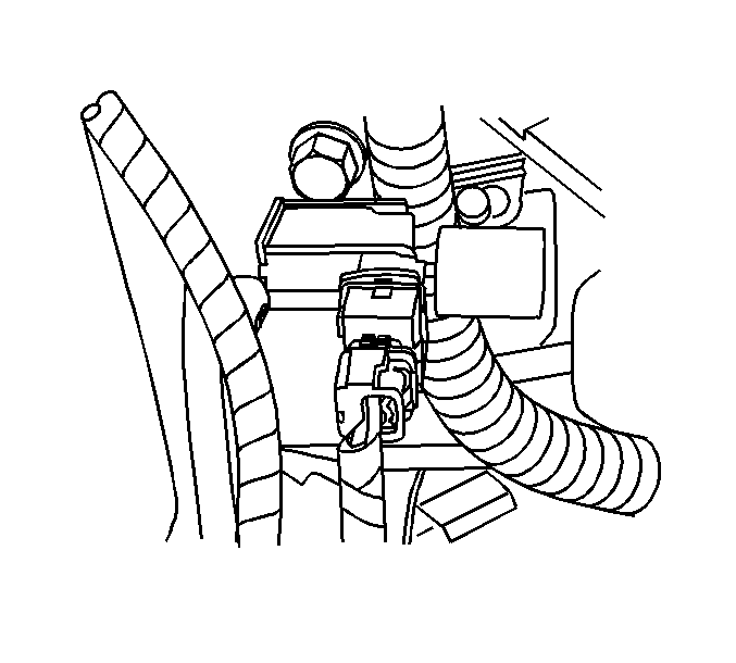
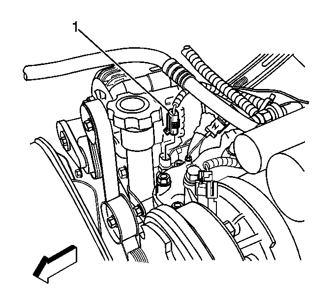
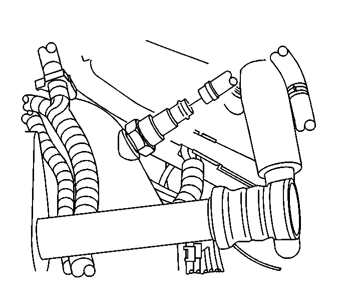
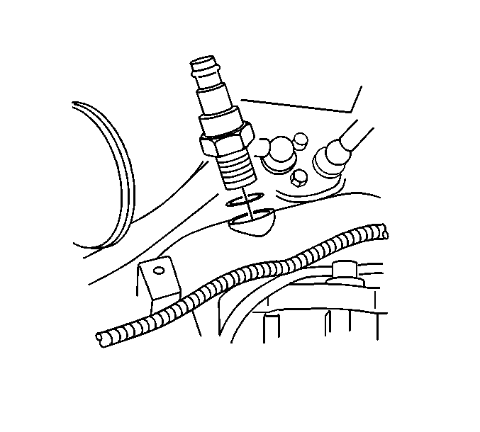
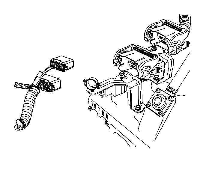
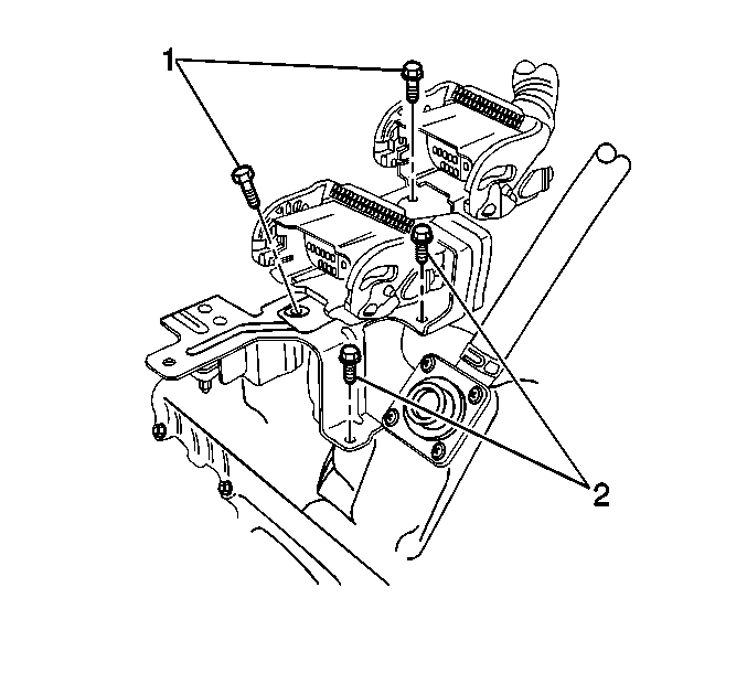
Important: Do not use a screwdriver or other tool to pry the hose loose. The hose can be torn or damaged. Loosen the hose by twisting.
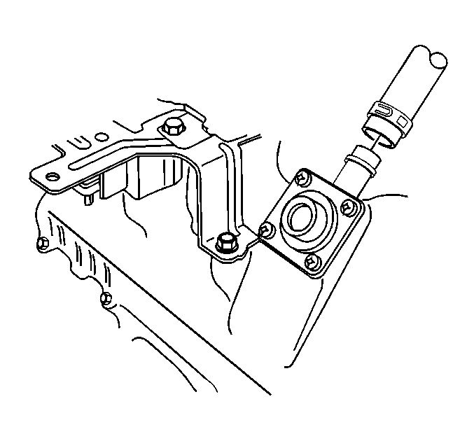
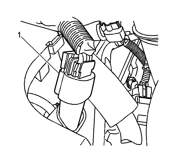
Installation Procedure
- Install the engine wiring harness.
- Connect the fuel pressure regulator electrical connector (1).
- Route the engine wiring harness to the engine.
- Raise the vehicle.
- Install the engine wiring harness ground bolts (1).
- Connect the CMP sensor electrical connector (1).
- Connect the CKP sensor electrical connector.
- Install the engine shield and bolts.
- Lower the vehicle.
- Connect the fuel rail pressure sensor electrical connector (1).
- Connect the BARO sensor electrical connector (1).
- Connect the oil level sensor electrical connector (1).
- Install the left side engine harness to the glow plugs (1).
- Install the glow plug electrical nuts.
- Install the left inner wheelhouse panel. Refer to Wheelhouse Panel Replacement in Body Front End.
- Install the fuel pipe retainer (2).
- Install the fuel pipe retainer nut at the valve cover.
- Connect the glow plug controller electrical connectors (1).
- Connect the fuel rail temperature sensor electrical connector (1).
- Connect the left rear fuel injector electrical connector (1).
- Connect the left front fuel injector electrical connector (1).
- Install the PCV hose to valve cover.
- Position the PCV hose clamp.
- Install the charged air cooler inlet duct to the turbocharger.
- Align the mark on the duct (2) with the mark on the turbocharger.
- Position the clamp (1) as shown for proper clearance.
- Install the bulk connector bolts (1) to the bracket.
- Connect the engine harness electrical connectors.
- Install the glow plug relay. Refer to Glow Plug Relay Replacement .
- Install the turbocharger coolant bypass valve.
- Install the turbocharger water inlet hose.
- Position the turbocharger water inlet hose clamp.
- Connect the ECT sensor electrical connector (1).
- Install the engine sight shield hold-down bracket (1) and bolt.
- Connect the turbocharger boost sensor electrical connector (1).
- Connect the right front fuel injector electrical connector (1).
- Install the right side engine harness to the glow plugs (1).
- Install the right side glow plug electrical nuts.
- Connect the EGR throttle valve solenoid electrical connector (1).
- Connect the EGR vacuum sensor electrical connector (1).
- Connect the EGR vent solenoid electrical connector (1).
- Connect the EGR valve solenoid electrical connector (1).
- Connect the right rear fuel injector electrical connector (1).
- Connect the following electrical connectors:
- Install the charged air cooler outlet duct to the intake.
- Tighten the charged air cooler outlet duct clamp (1).
- Connect the fuel injection control module electrical connectors (1).
- Install the air cleaner. Refer to Air Cleaner Assembly Replacement .
- Connect the negative battery cable. Refer to Battery Negative Cable Disconnection and Connection in Engine Electrical.


Notice: Refer to Fastener Notice in the Preface section.

Tighten
Tighten the bolts to 34 N·m (25 lb ft).


Tighten
Tighten the bolts to 20 N·m (15 lb ft).


Tighten
Tighten the nuts to 2 N·m (18 lb in).

Tighten
Tighten the nut to 8 N·m (70 lb in).


Tighten
Tighten the clamp to 6 N·m (53 lb in).

Tighten
Tighten the bolts to 21 N·m (15 lb ft).


Tighten
Tighten the valve to 60 N·m (44 lb ft).


Tighten
Tighten the bolt to 10 N·m (89 lb in).


Tighten
Tighten the nuts to 2 N·m (18 lb in).


| • | Water-in-fuel sensor (1) |
| • | Fuel heater (2) |

Tighten
Tighten the clamp to 6 N·m (53 lb in).

