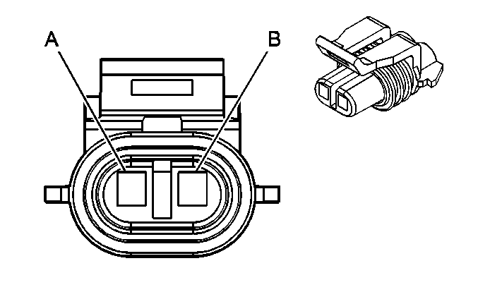
| |||||||
|---|---|---|---|---|---|---|---|
Connector Part Information |
| ||||||
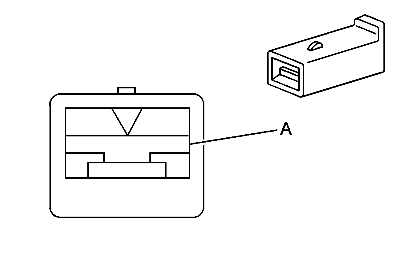
Pin | Wire Color | Circuit No. | Function | ||||
A | BRN | 241 | Ignition 3 Voltage | ||||
B | BLK | 550 | Ground | ||||
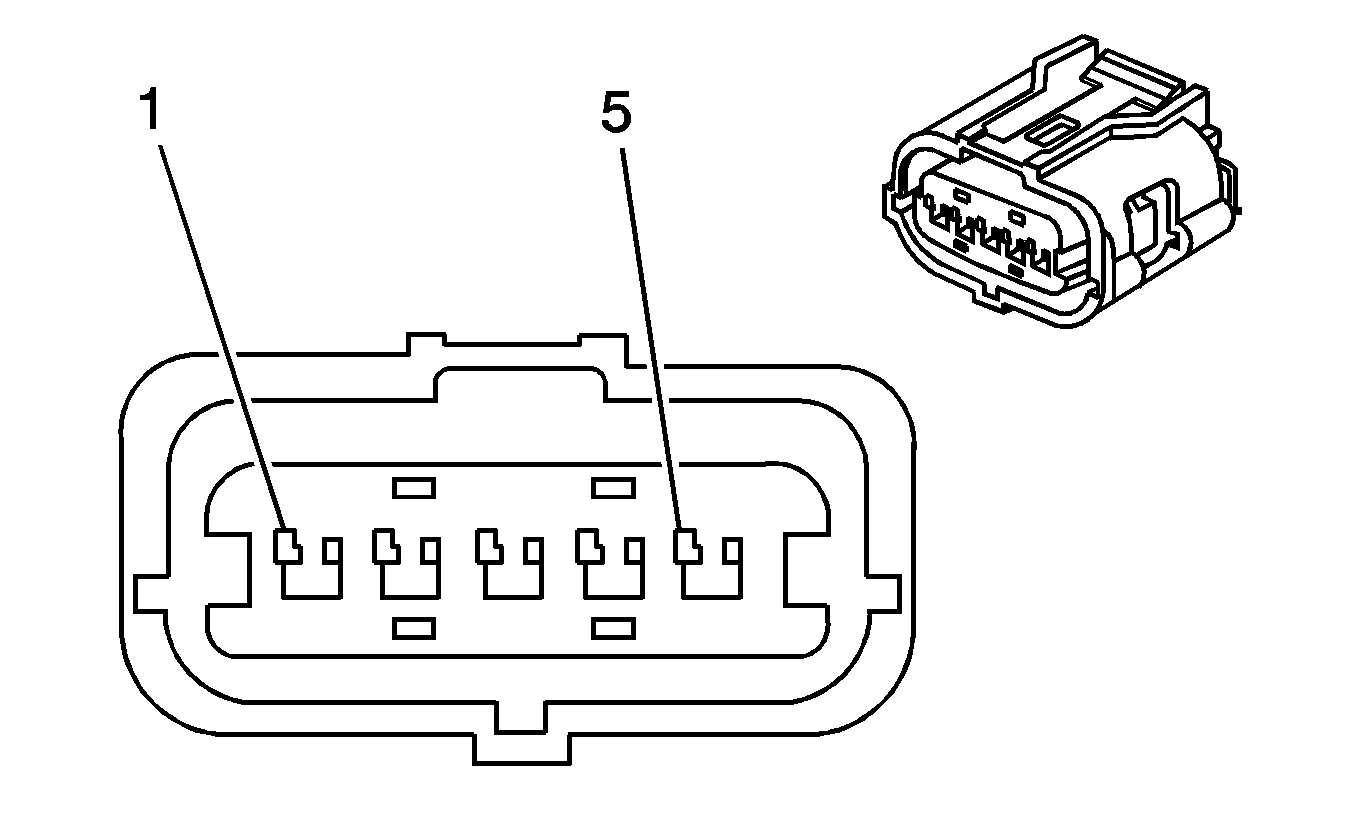
| |||||||
|---|---|---|---|---|---|---|---|
Connector Part Information |
| ||||||
Pin | Wire Color | Circuit No. | Function | ||||
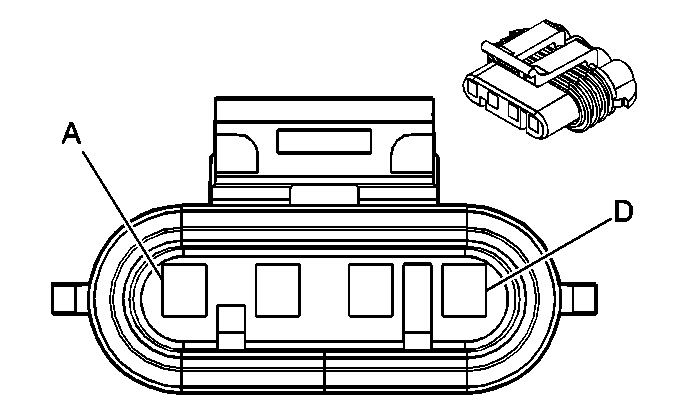
1 | WHT | 1-BCO | Ground | ||||
2 | WHT | 2-BCO | BCO Status | ||||
3 | WHT | 3-BCO | BCO Control - A | ||||
4 | WHT | 4-BCO | BCO Control - B | ||||
5 | WHT | 5-BCO | Battery Positive Voltage | ||||
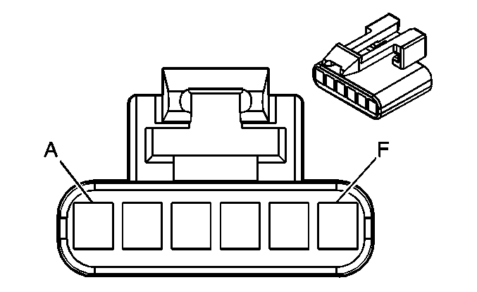
| |||||||
|---|---|---|---|---|---|---|---|
Connector Part Information |
| ||||||
Pin | Wire Color | Circuit No. | Function | ||||
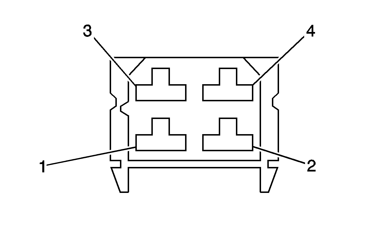
A | PPL | 420 | Cruise Control Release Signal | ||||
B | BRN/WHT | 379 | CPP Switch Signal | ||||
C | PNK | 639 | Ignition 1 Voltage | ||||
D | DK GRN | 1433 | Clutch Start Switch Signal | ||||
E | BRN | 441 | Ignition 3 Voltage | ||||
F | GRY | 48 | CPP Switch Signal | ||||
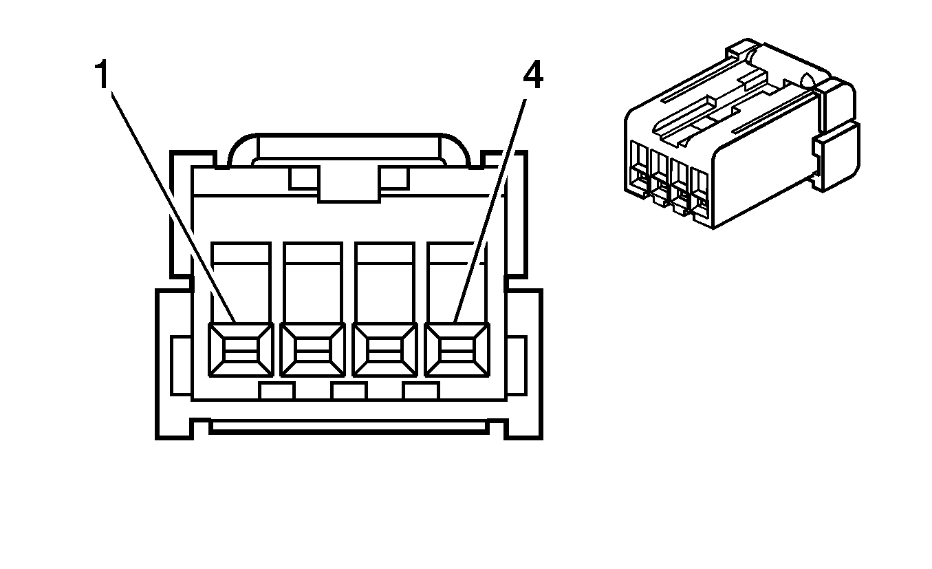
| |||||||
|---|---|---|---|---|---|---|---|
Connector Part Information |
| ||||||
Pin | Wire Color | Circuit No. | Function | ||||
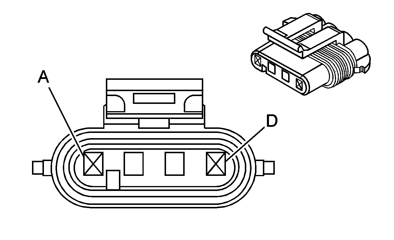
1 | WHT | 1-CS | Current Sensor Signal - A | ||||
2 | WHT | 2-CS | Current Sensor Signal - B | ||||
3 | WHT | 3-CS | Compensating Coil Voltage | ||||
4 | WHT | 4-CS | Low Reference | ||||
| |||||||
|---|---|---|---|---|---|---|---|
Connector Part Information |
| ||||||
Pin | Wire Color | Circuit No. | Function | ||||
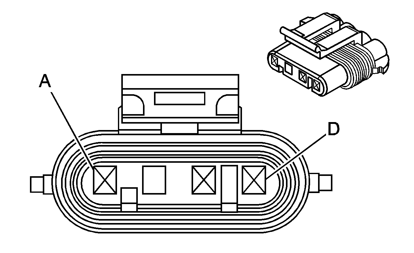
1 | WHT | 1-FAN | Fan Speed Signal | ||||
2 | WHT | 2-FAN | Low Reference | ||||
3 | -- | -- | Not Used | ||||
4 | WHT | 4-FAN | 5 Volt Reference | ||||
| |||||||
|---|---|---|---|---|---|---|---|
Connector Part Information |
| ||||||
Pin | Wire Color | Circuit No. | Function | ||||
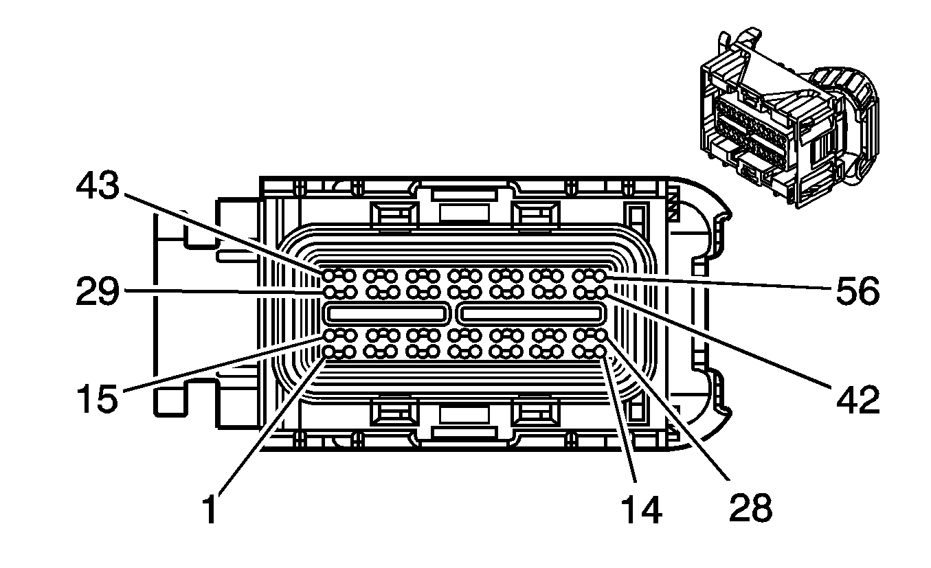
1 | WHT | 1-NTC-1 | Temperature Sensor Signal - 1 | ||||
2 | WHT | 1-NTC-2 | Temperature Sensor Signal - 2 | ||||
3 - 7 | -- | -- | Not Used | ||||
8 | WHT | 2-BCO | BCO Control - A | ||||
9 | WHT | 4-BCO | BCO Control - B | ||||
10 | WHT | 2-BCO | BCO Status | ||||
11 | WHT | 1-BCO | Ground | ||||
12 | WHT | 2-CS | Current Sensor Signal - A | ||||
13 | WHT | 3-CS | Compensating Coil Voltage | ||||
14 | WHT | 5-BCO | Battery Positive Voltage | ||||
15 | WHT | 2-FAN | Low Reference | ||||
16 | -- | -- | Not Used | ||||
17 | WHT | 2-NTC-2 | Low Reference | ||||
18 | WHT | 2-NTC-1 | Low Reference | ||||
19 | WHT | 2-NTC-3 | Low Reference | ||||
20 | WHT | 1-NTC-3 | Temperature Sensor Signal - 3 | ||||
21 | WHT | 1-R2 | Voltage Sensor Signal - 2 | ||||
22 | -- | -- | Not Used | ||||
23 | WHT | 1-R1 | Voltage Sensor Signal - 1 | ||||
24 | WHT | 1-R4 | Voltage Sensor Signal - 4 | ||||
25 | WHT | 1-R3 | Voltage Sensor Signal - 3 | ||||
26 | -- | -- | Not Used | ||||
27 | WHT | 1-CS | Current Sensor Signal - A | ||||
28 | WHT | 4-CS | Low Reference | ||||
29 | WHT | 4-FAN | 5 Volt Reference | ||||
30 | WHT | 1-FAN | Fan Speed Signal | ||||
| |||||||
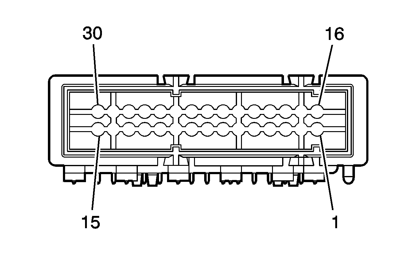
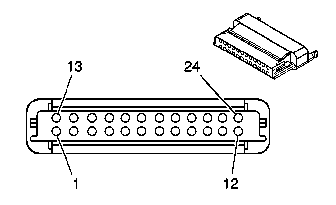
|---|---|---|---|---|---|---|---|
Connector Part Information |
| ||||||
Pin | Wire Color | Circuit No. | Function | ||||
1 - 14 | -- | -- | Not Used | ||||
15 | WHT | 1-CAR | High Speed GMLAN Serial Data (+) | ||||
18 | WHT | 7-CAR | Ignition 1 Voltage | ||||
19 - 23 | -- | -- | Not Used | ||||
24 | WHT | GND-CAR | Ground | ||||
25 - 38 | -- | -- | Not Used | ||||
39 | WHT | 2-CAR | High Speed GMLAN Serial Data (-) | ||||
40 - 41 | -- | -- | Not Used | ||||
42 | WHT | 8-CAR | Ignition 0 Voltage | ||||
43 - 47 | -- | -- | Not Used | ||||
48 | WHT | 3-CAR | Battery Positive Voltage | ||||
| |||||||
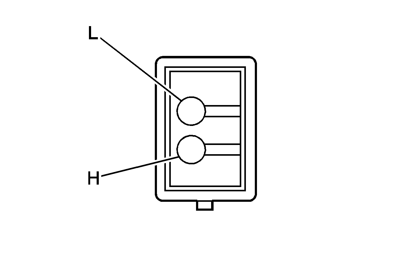
|---|---|---|---|---|---|---|---|
Connector Part Information |
| ||||||
Pin | Wire Color | Circuit No. | Function | ||||
L - H | -- | -- | Not Used | ||||
| |||||||
|---|---|---|---|---|---|---|---|
Connector Part Information |
| ||||||
Pin | Wire Color | Circuit No. | Function | ||||
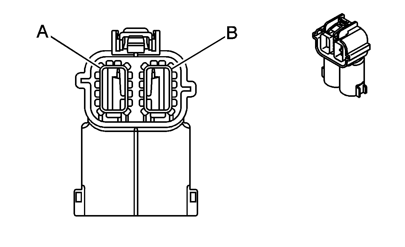
A | DK BLU | 5668 | Engine On Signal | ||||
B | BRN | 25 | Charge Indicator Control | ||||
C | GRY | 23 | Generator Field Duty Cycle Signal | ||||
D | -- | -- | Not Used | ||||
| |||||||
|---|---|---|---|---|---|---|---|
Connector Part Information |
| ||||||
Pin | Wire Color | Circuit No. | Function | ||||
A | -- | -- | Not Available | ||||
B | BRN | 25 | Charge Indicator Control | ||||
C | GRY | 23 | Generator Field Duty Cycle Signal | ||||
D | -- | -- | Not Available | ||||
|
| |||||||
|---|---|---|---|---|---|---|---|
Connector Part Information |
| ||||||
Pin | Wire Color | Circuit No. | Function | ||||
A | -- | -- | Not Available | ||||
B | BRN | 25 | Charge Indicator Control | ||||
C | GRY | 23 | Generator Field Duty Cycle Signal | ||||
D | -- | -- | Not Available | ||||
| |||||||
|---|---|---|---|---|---|---|---|
Connector Part Information |
| ||||||
Pin | Wire Color | Circuit No. | Function | ||||
A | -- | -- | Not Available | ||||
B | BRN | 2524 | Generator 2 Turn On Signal | ||||
C-D | -- | -- | Not Available | ||||
| |||||||
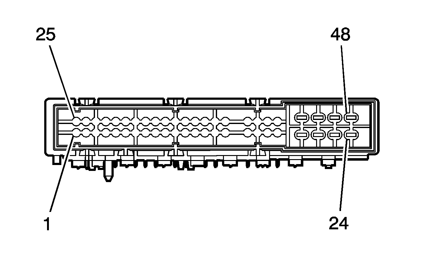
|---|---|---|---|---|---|---|---|
Connector Part Information |
| ||||||
Pin | Wire Color | Circuit No. | Function | ||||
1 | ORN | 1940 | Battery Positive Voltage | ||||
2 | PNK | 1020 | Ignition 0 Voltage | ||||
3 - 7 | -- | -- | Not Used | ||||
8 | PNK/BLK | 109 | Hood Ajar Switch Signal | ||||
9 | PPL | 5681 | APO Switch Signal | ||||
10 - 11 | -- | -- | Not Used | ||||
12 | PNK | 1939 | Ignition 1 Voltage | ||||
13 - 27 | -- | -- | Not Used | ||||
28 | PPL/WHT | 5687 | Class 2 Serial Data | ||||
29 | BLK/WHT | 451 | Ground | ||||
30 - 33 | -- | -- | Not Used | ||||
34 | ORN/BLK | 1057 | Low Reference | ||||
35 - 39 | -- | -- | Not Used | ||||
40 | TAN/WHT | 2500 | High Speed GMLAN Serial Data (+) | ||||
41 | TAN | 2501 | High Speed GMLAN Serial Data (-) | ||||
42 | -- | -- | Not Used | ||||
43 | BLK/WHT | 451 | Ground | ||||
44 | -- | -- | Not Used | ||||
45 | YEL | 5680 | APO Switch Indicator Control | ||||
46 - 47 | -- | -- | Not Used | ||||
48 | PNK/WHT | 5537 | Transmission Pump Relay Control | ||||
49 | PPL/WHT | 5539 | Power Maintain Relay Coil Control | ||||
50 | -- | -- | Not Used | ||||
51 | WHT | 5542 | Auxiliary Heater Pump Relay Control | ||||
52 | BRN/WHT | 5682 | Low Reference | ||||
53 | -- | -- | Not Used | ||||
54 | TAN/WHT | 2500 | High Speed GMLAN Serial Data (+) | ||||
55 | TAN | 2501 | High Speed GMLAN Serial Data (-) | ||||
56 | -- | -- | Not Used | ||||
| |||||||
|---|---|---|---|---|---|---|---|
Connector Part Information |
| ||||||
Pin | Wire Color | Circuit No. | Function | ||||
A | -- | -- | Not Used | ||||
B | -- | -- | Not Used | ||||

| |||||||
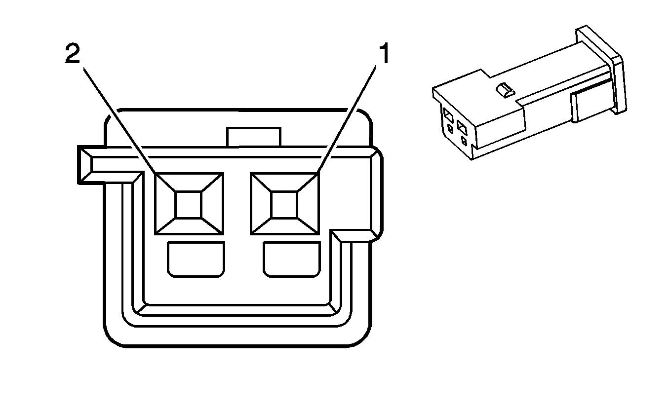
|---|---|---|---|---|---|---|---|
Connector Part Information |
| ||||||
Pin | Wire Color | Circuit No. | Function | ||||
A | BLK | 50 | Ground | ||||
B | RED | 102 | Battery Positive Voltage | ||||

| |||||||
|---|---|---|---|---|---|---|---|
Connector Part Information |
| ||||||
Pin | Wire Color | Circuit No. | Function | ||||
A | RED | 5084 | High Voltage Battery (+) | ||||
B | BLK | 5691 | High Voltage Battery (-) | ||||
| |||||||
|---|---|---|---|---|---|---|---|
Connector Part Information |
| ||||||
Pin | Wire Color | Circuit No. | Function | ||||
1 | TAN/WHT | 2500 | High Speed GMLAN Serial Data (+) | ||||
2 | TAN/WHT | 2500 | High Speed GMLAN Serial Data (+) | ||||
3 - 6 | -- | -- | Not Used | ||||
7 | YEL/BLK | 625 | Starter Enable Relay Control | ||||
8 | PNK | 1020 | Ignition 0 Voltage | ||||
9 | LT BLU/BLK | 647 | Medium Resolution Engine Speed Signal | ||||
10 - 11 | -- | -- | Not Used | ||||
12 | WHT | 2368 | Cooling Fan Clutch Supply Voltage | ||||
13 | TAN | 2501 | High Speed GMLAN Serial Data (-) | ||||
14 | TAN | 2501 | High Speed GMLAN Serial Data (-) | ||||
15 - 20 | -- | -- | Not Used | ||||
21 | WHT | 121 | Engine Speed Signal | ||||
22 - 23 | -- | -- | Not Used | ||||
24 | PNK | 2014 | Coolant Pump Relay Control | ||||
| |||||||
|---|---|---|---|---|---|---|---|
Connector Part Information |
| ||||||
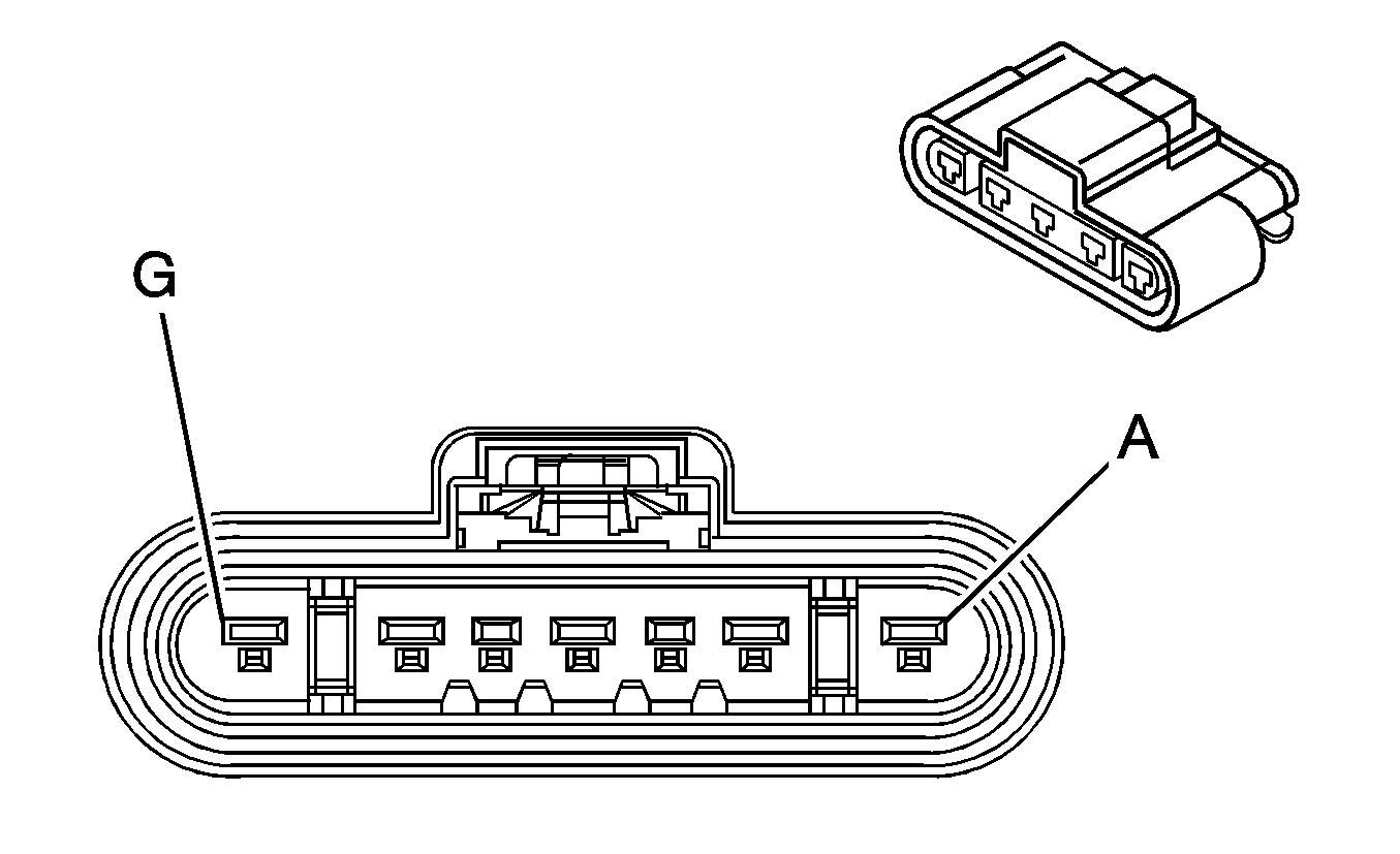
Pin | Wire Color | Circuit No. | Function | ||||
A | -- | -- | Not Used | ||||
B | WHT | 5685 | APO Neutral | ||||
C | ORN | 5595 | High Voltage Interlock Loop Signal - 2 | ||||
D | BLK | 50 | Ground | ||||
E | PPL | 5087 | High Voltage Interlock Loop Signal - 1 | ||||
F | DK GRN | 5686 | Ground | ||||
G | BLK | 5683 | APO Phase A | ||||
| |||||||
|---|---|---|---|---|---|---|---|
Connector Part Information |
| ||||||
Pin | Wire Color | Circuit No. | Function | ||||
1 | WHT | 1-NTC-1 | Temperature Sensor Signal - 1 | ||||
2 | WHT | 2-NTC-1 | Low Reference | ||||
|
| |||||||
|---|---|---|---|---|---|---|---|
Connector Part Information |
| ||||||
Pin | Wire Color | Circuit No. | Function | ||||
1 | WHT | 1-NTC-2 | Temperature Sensor Signal - 2 | ||||
2 | WHT | 2-NTC-2 | Low Reference | ||||
|
| |||||||
|---|---|---|---|---|---|---|---|
Connector Part Information |
| ||||||
Pin | Wire Color | Circuit No. | Function | ||||
1 | WHT | 1-NTC-3 | Temperature Sensor Signal - 3 | ||||
2 | WHT | 2-NTC-3 | Low Reference | ||||
| |||||||
|---|---|---|---|---|---|---|---|
Connector Part Information |
| ||||||
Pin | Wire Color | Circuit No. | Function | ||||
A | WHT | 1-R1 | Voltage Sensor Signal - 1 | ||||
|
| |||||||
|---|---|---|---|---|---|---|---|
Connector Part Information |
| ||||||
Pin | Wire Color | Circuit No. | Function | ||||
A | WHT | 1-R2 | Voltage Sensor Signal - 2 | ||||
|
| |||||||
|---|---|---|---|---|---|---|---|
Connector Part Information |
| ||||||
Pin | Wire Color | Circuit No. | Function | ||||
A | WHT | 1-R3 | Voltage Sensor Signal - 3 | ||||
|
| |||||||
|---|---|---|---|---|---|---|---|
Connector Part Information |
| ||||||
Pin | Wire Color | Circuit No. | Function | ||||
A | WHT | 1-R4 | Voltage Sensor Signal - 4 | ||||
