| |||||||
|---|---|---|---|---|---|---|---|
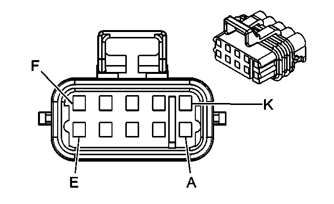
Connector Part Information |
| ||||||
Pin | Wire Color | Circuit No. | Function | ||||
A | GY | 1273 | Low Reference | ||||
B | PU | 1272 | Low Reference | ||||
C | L-BU | 1162 | APP Sensor 2 Signal | ||||
D | TN | 1274 | 5-Volt Reference | ||||
E | BN | 1271 | Low Reference | ||||
F | D-BU | 1161 | APP Sensor 1 Signal | ||||
G | WH/BK | 1164 | 5-Volt Reference | ||||
H | -- | -- | Not Used | ||||
J | YE/BK | 1275 | 5-Volt Reference | ||||
K | D-GN | 1163 | APP Sensor 3 Signal | ||||
| |||||||
|---|---|---|---|---|---|---|---|
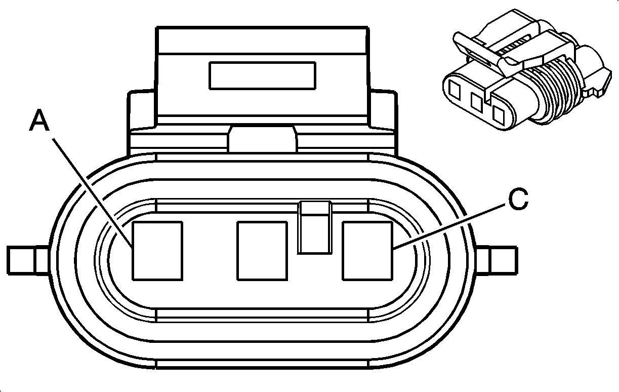
Connector Part Information |
| ||||||
Pin | Wire Color | Circuit No. | Function | ||||
A | OG/BK | 1057 | Low Reference | ||||
B | GY/BK | 433 | BARO Sensor Signal | ||||
C | WH/BK | 2932 | 5-Volt Reference | ||||

| |||||||
|---|---|---|---|---|---|---|---|
Connector Part Information |
| ||||||
Pin | Wire Color | Circuit No. | Function | ||||
A | OG/BK | 469 | Low Reference | ||||
B | L-GN | 432 | Turbocharger Boost Sensor Signal | ||||
C | GY | 597 | 5-Volt Reference | ||||
| |||||||
|---|---|---|---|---|---|---|---|
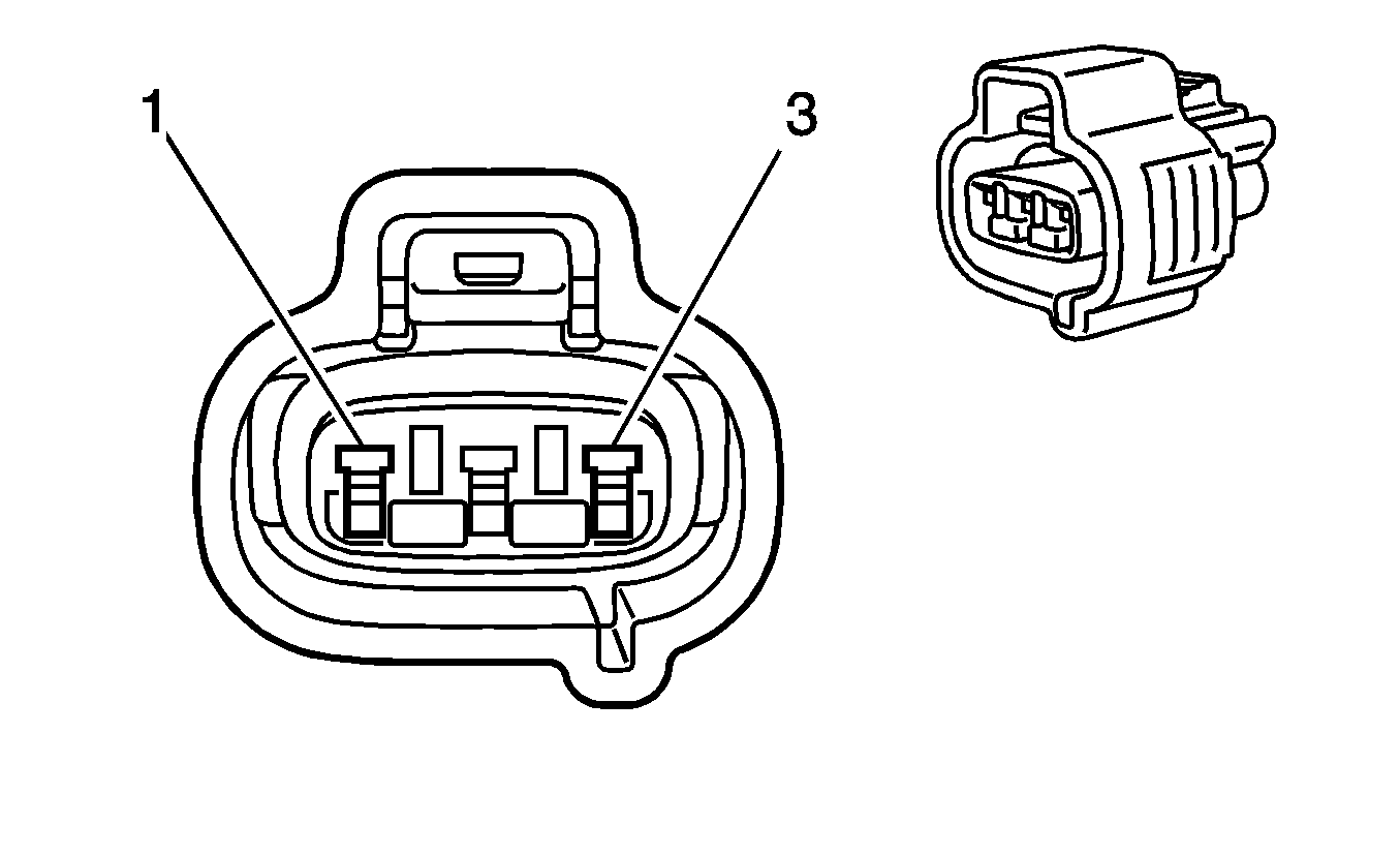
Connector Part Information |
| ||||||
Pin | Wire Color | Circuit No. | Function | ||||
1 | BN/WH | 633 | CMP Sensor Signal | ||||
2 | PK/BK | 632 | Low Reference | ||||
3 | RD | 631 | 5-Volt Reference | ||||

| |||||||
|---|---|---|---|---|---|---|---|
Connector Part Information |
| ||||||
Pin | Wire Color | Circuit No. | Function | ||||
1 | D-BU/WH | 1869 | CKP Sensor Signal | ||||
2 | YE/BK | 1868 | Low Reference | ||||
3 | L-GN | 1867 | 12-Volt Reference | ||||
| |||||||
|---|---|---|---|---|---|---|---|
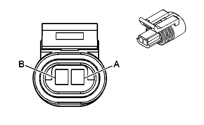
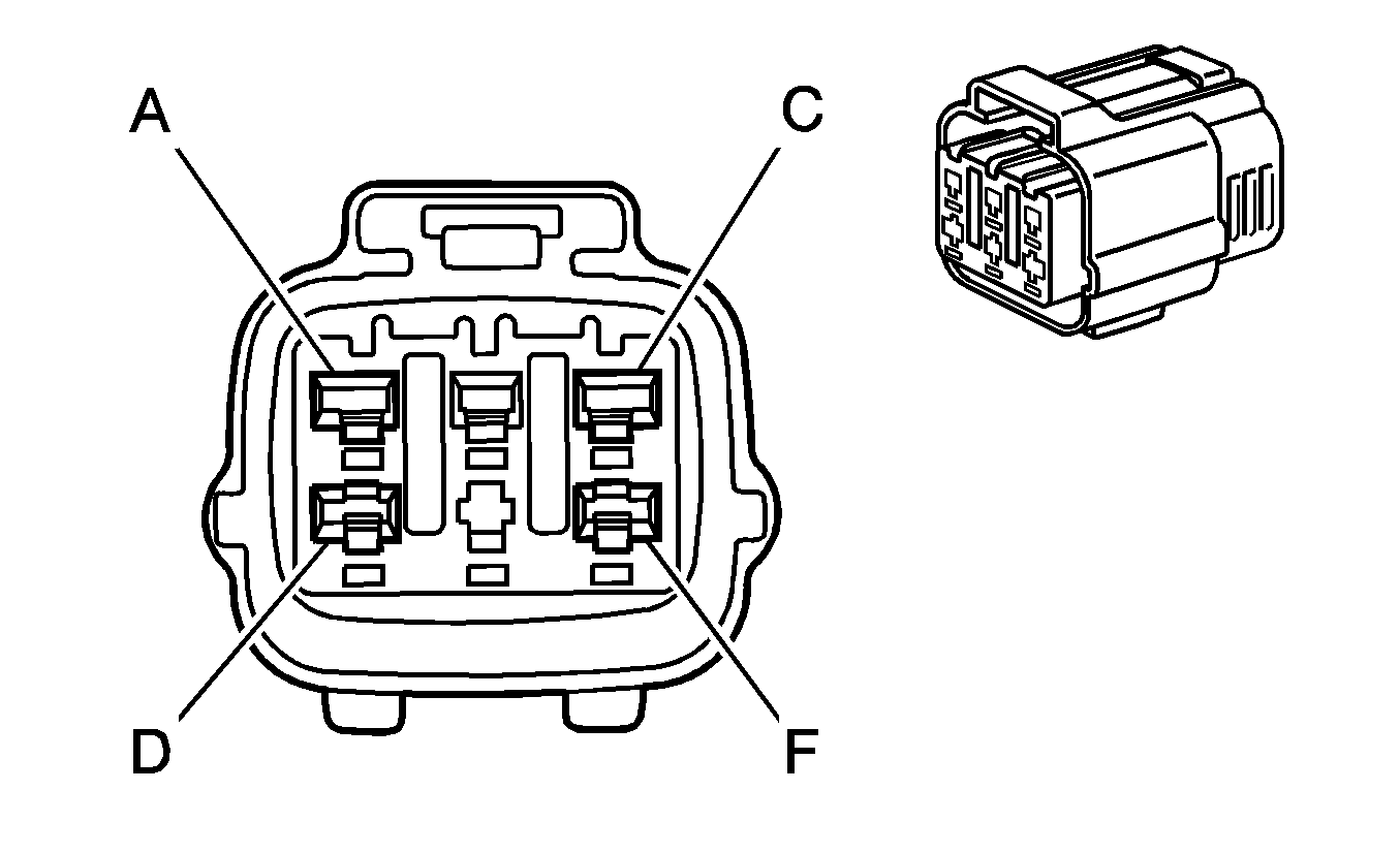
Connector Part Information |
| ||||||
Pin | Wire Color | Circuit No. | Function | ||||
A | GY | 720 | Low Reference | ||||
B | YE | 410 | ECT Sensor Signal | ||||
| |||||||
|---|---|---|---|---|---|---|---|
Connector Part Information |
| ||||||
Pin | Wire Color | Circuit No. | Function | ||||
A | PU | 2703 | 5-Volt Reference | ||||
B | YE/BK | 2754 | Low Reference | ||||
C | D-BU/WH | 5763 | EGR Valve Position Signal | ||||
D | PK | 5764 | EGR Motor High Control | ||||
E | -- | -- | Not Used | ||||
F | WH | 5746 | EGR Motor Low Control | ||||
| |||||||
|---|---|---|---|---|---|---|---|
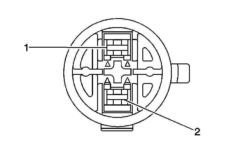
Connector Part Information |
| ||||||
Pin | Wire Color | Circuit No. | Function | ||||
1 | PK | 239 | Ignition 1 Voltage | ||||
2 | BK | 50 | Ground | ||||
| |||||||
|---|---|---|---|---|---|---|---|
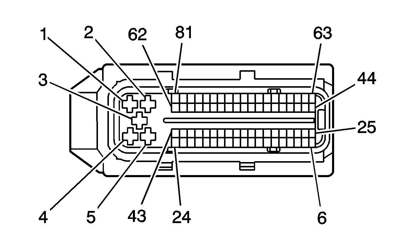
Connector Part Information |
| ||||||
Pin | Wire Color | Circuit No. | Function | ||||
1 | WH/L-GN | IC18 | Fuel Injector 4 Command | ||||
2 | YE/BK | IZ17 | Ground | ||||
3 | OG | IC13 | Injector Supply Voltage | ||||
4 | RD/L-GN | IC15 | Fuel Injector 1 Command | ||||
5 | PK | 339 | Ignition 1 Voltage | ||||
6-43 | -- | -- | Not Used | ||||
44 | L-BU/BK | 844 | Fuel Injector 4 Control | ||||
45 | BK/WH | 845 | Fuel Injector 5 Control | ||||
46 | -- | -- | Not Used | ||||
47 | PK/BK | 1746 | Fuel Injector 3 Control | ||||
48 | RD/BK | 877 | Fuel Injector 7 Control | ||||
49-58 | -- | -- | Not Used | ||||
59 | D-BU/WH | IC20 | Fuel Injector 6 Command | ||||
60 | D-BU/WH | IC520 | Fuel Injector 6 Command | ||||
61 | WH/RD | IC21 | Fuel Injector 7 Command | ||||
62 | WH/RD | IC521 | Fuel Injector 7 Command | ||||
63 | D-BU/WH | 878 | Fuel Injector 8 Control | ||||
64 | YE/BK | 846 | Fuel Injector 6 Control | ||||
65 | -- | -- | Not Used | ||||
66 | BK | 1744 | Fuel Injector 1 Control | ||||
67 | L-GN/BK | 1745 | Fuel Injector 2 Control | ||||
68-81 | -- | -- | Not Used | ||||
| |||||||
|---|---|---|---|---|---|---|---|
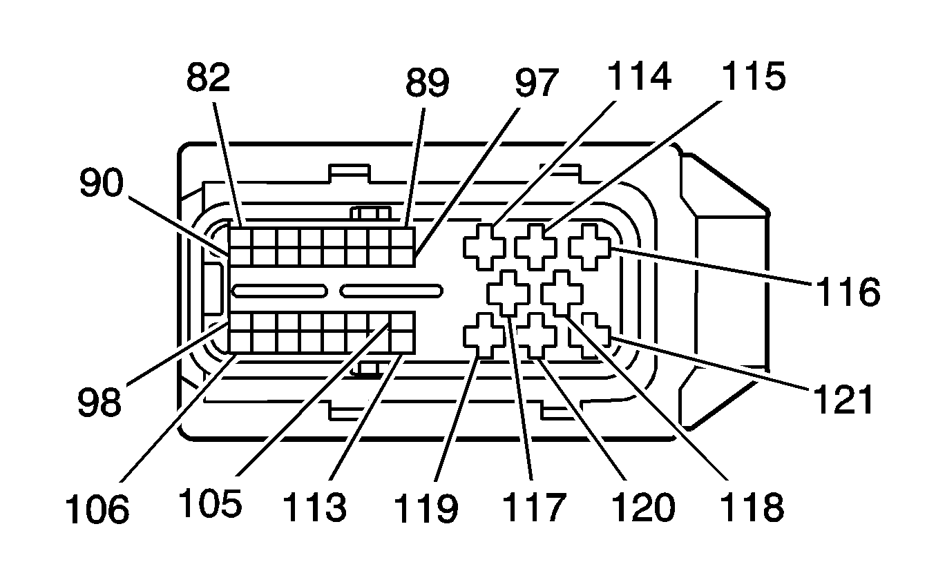
Connector Part Information |
| ||||||
Pin | Wire Color | Circuit No. | Function | ||||
82-89 | -- | -- | Not Used | ||||
90 | D-GN | 2362 | SAE J1939 Serial Data Bus - | ||||
91 | YE | 2361 | SAE J1939 Serial Data Bus + | ||||
92-93 | -- | -- | Not Used | ||||
94 | L-BU | 2832 | Engine Speed Signal | ||||
95-113 | -- | -- | Not Used | ||||
114 | BK/GN | IZ18 | Ground | ||||
115 | WH/L-BU | IC17 | Fuel Injector 3 Command | ||||
116 | RD/L-GN | IC19 | Fuel Injector 5 Command | ||||
117 | -- | -- | Not Used | ||||
118 | RD/WH | IC60 | Injector Supply Voltage | ||||
119 | PK | 339 | Ignition 1 Voltage | ||||
120 | WH/GN | IC22 | Fuel Injector 8 Command | ||||
121 | WH/YE | IC16 | Fuel Injector 2 Command | ||||
| |||||||
|---|---|---|---|---|---|---|---|
Connector Part Information |
| ||||||
Pin | Wire Color | Circuit No. | Function | ||||
1 | RD/L-GN | IC15 | Fuel Injector 1 Command | ||||
2 | OG | IC13 | Injector Supply Voltage | ||||

| |||||||
|---|---|---|---|---|---|---|---|
Connector Part Information |
| ||||||
Pin | Wire Color | Circuit No. | Function | ||||
1 | WH/YE | IC16 | Fuel Injector 2 Command | ||||
2 | RD/WH | IC14 | Injector Supply Voltage | ||||

| |||||||
|---|---|---|---|---|---|---|---|
Connector Part Information |
| ||||||
Pin | Wire Color | Circuit No. | Function | ||||
1 | WH/BU | IC17 | Fuel Injector 3 Command | ||||
2 | RD/WH | IC60 | Injector Supply Voltage | ||||

| |||||||
|---|---|---|---|---|---|---|---|
Connector Part Information |
| ||||||
Pin | Wire Color | Circuit No. | Function | ||||
1 | WH/L-GN | IC18 | Fuel Injector 4 Command | ||||
2 | OG | IC62 | Injector Supply Voltage | ||||

| |||||||
|---|---|---|---|---|---|---|---|
Connector Part Information |
| ||||||
Pin | Wire Color | Circuit No. | Function | ||||
1 | RD/L-GN | IC19 | Fuel Injector 5 Command | ||||
2 | RD/WH | IC61 | Injector Supply Voltage | ||||

| |||||||
|---|---|---|---|---|---|---|---|
Connector Part Information |
| ||||||
Pin | Wire Color | Circuit No. | Function | ||||
1 | D-BU/WH | IC20 | Fuel Injector 6 Command | ||||
2 | OG | IC64 | Injector Supply Voltage | ||||

| |||||||
|---|---|---|---|---|---|---|---|
Connector Part Information |
| ||||||
Pin | Wire Color | Circuit No. | Function | ||||
1 | WH/RD | IC21 | Fuel Injector 7 Command | ||||
2 | OG | IC63 | Injector Supply Voltage | ||||

| |||||||
|---|---|---|---|---|---|---|---|
Connector Part Information |
| ||||||
Pin | Wire Color | Circuit No. | Function | ||||
1 | WH/GN | IC22 | Fuel Injector 8 Command | ||||
2 | RD/WH | IC65 | Injector Supply Voltage | ||||

| |||||||
|---|---|---|---|---|---|---|---|
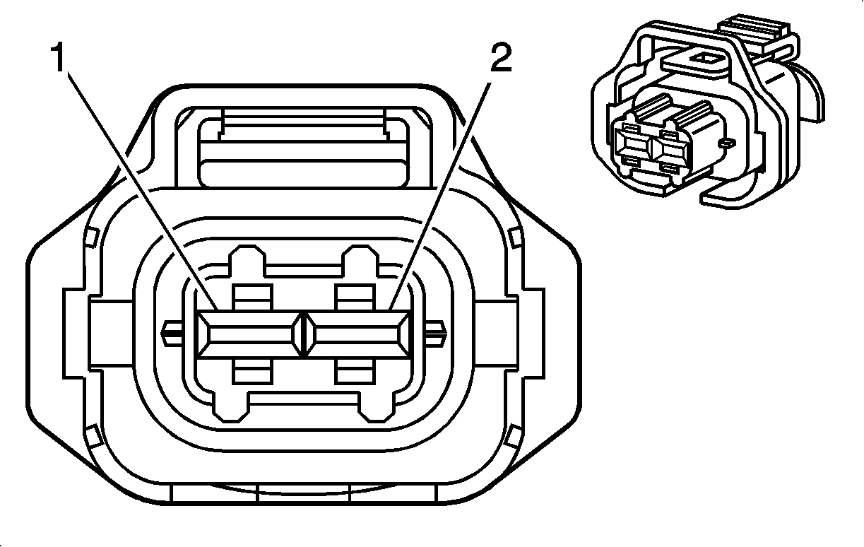
Connector Part Information |
| ||||||
Pin | Wire Color | Circuit No. | Function | ||||
1 | PU/WH | 2530 | Fuel Pressure Regulator Solenoid Supply Voltage | ||||
2 | YE | 2834 | Fuel Pressure Solenoid Control | ||||
| |||||||
|---|---|---|---|---|---|---|---|
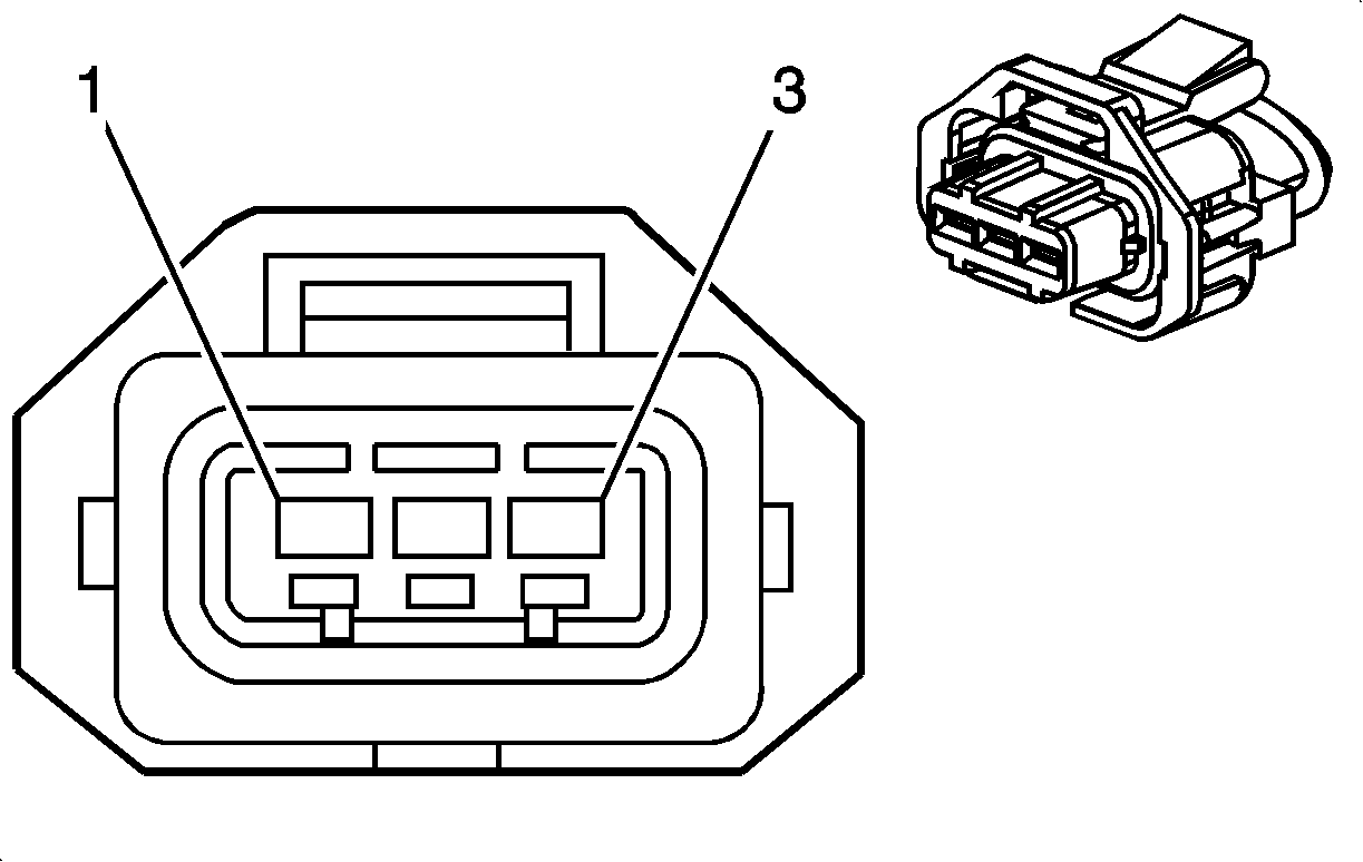
Connector Part Information |
| ||||||
Pin | Wire Color | Circuit No. | Function | ||||
1 | OG/BK | 2919 | Low Reference | ||||
2 | YE | 2918 | FRP Sensor Signal | ||||
3 | TN | 2917 | 5-Volt Reference | ||||
| |||||||
|---|---|---|---|---|---|---|---|
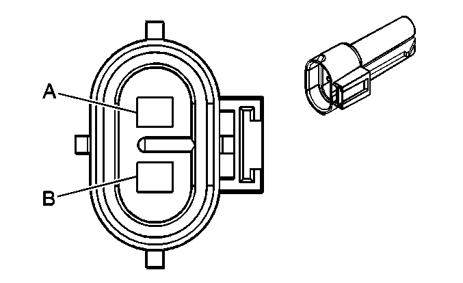
Connector Part Information |
| ||||||
Pin | Wire Color | Circuit No. | Function | ||||
A | GY | 120 | Fuel Pump Supply Voltage | ||||
B | BK | 1650 | Ground (20 Series) | ||||
BK | 2150 | Ground (30 Series) | |||||
| |||||||
|---|---|---|---|---|---|---|---|
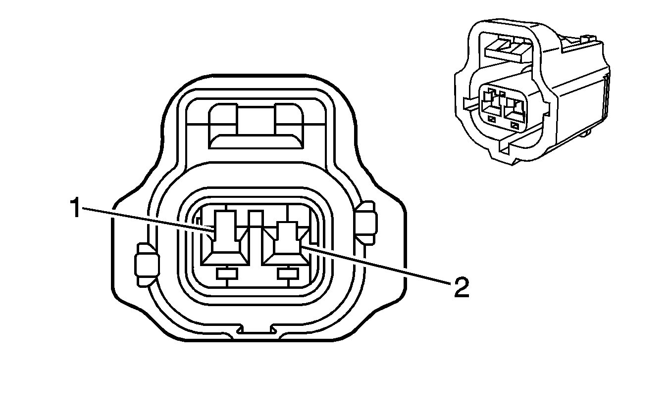
Connector Part Information |
| ||||||
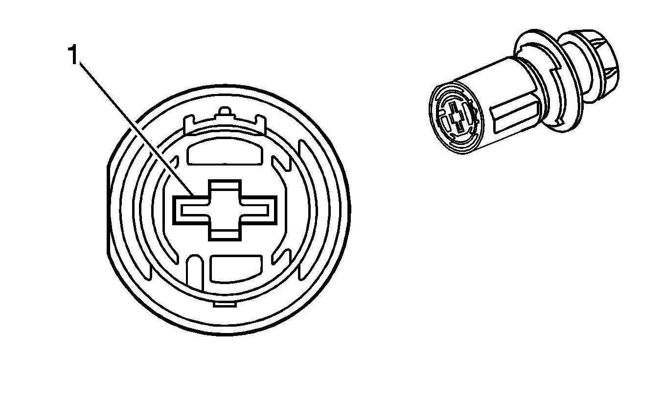
Pin | Wire Color | Circuit No. | Function | ||||
1 | YE | 1578 | Fuel Temperature Signal | ||||
2 | BN | 718 | Low Reference | ||||
| |||||||
|---|---|---|---|---|---|---|---|
Connector Part Information |
| ||||||
Pin | Wire Color | Circuit No. | Function | ||||
1 | BK | 1042 | Battery Positive Voltage | ||||
| |||||||
|---|---|---|---|---|---|---|---|
Connector Part Information |
| ||||||
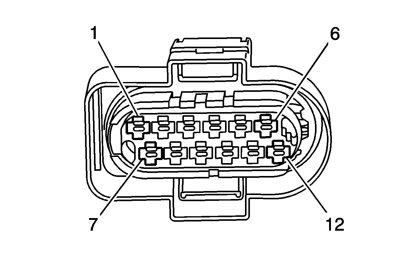
Pin | Wire Color | Circuit No. | Function | ||||
1 | RD/GN | HB11 | Glow Plug 1 Supply Voltage | ||||
2 | WH/GN | HB12 | Glow Plug 2 Supply Voltage | ||||
3 | RD/WH | HB13 | Glow Plug 3 Supply Voltage | ||||
4 | WH/YE | HB14 | Glow Plug 4 Supply Voltage | ||||
5 | PK | 239 | Ignition 1 Voltage | ||||
6 | D-GN | 2362 | SAE J1939 Serial Data Bus | ||||
7 | RD/L-GN | HB15 | Glow Plug 5 Supply Voltage | ||||
8 | WH/L-GN | HB16 | Glow Plug 6 Supply Voltage | ||||
9 | RD/BU | HB17 | Glow Plug 7 Supply Voltage | ||||
10 | WH/BU | HB18 | Glow Plug 8 Supply Voltage | ||||
11 | PK/YE | HB03 | Ground | ||||
12 | YE | 2361 | SAE J1939 Serial Data Bus + | ||||
| |||||||
|---|---|---|---|---|---|---|---|
Connector Part Information |
| ||||||
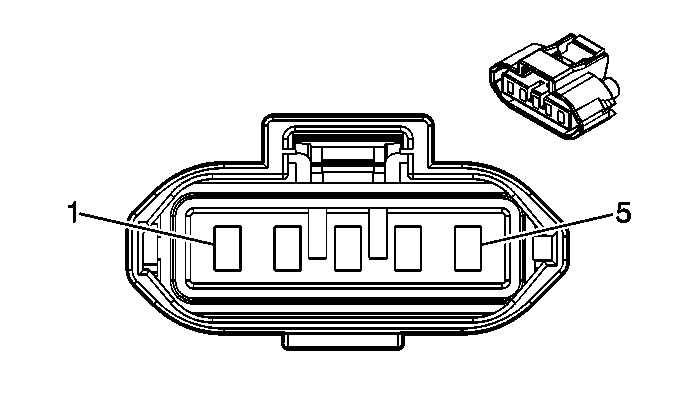
Pin | Wire Color | Circuit No. | Function | ||||
1 | BK | 552 | Low Reference | ||||
2 | TN | 472 | IAT Sensor Signal | ||||
3 | PK | 439 | Ignition 1 Voltage | ||||
4 | GY/BK | 2931 | Low Reference | ||||
5 | YE | 492 | MAF Sensor Signal | ||||
| |||||||
|---|---|---|---|---|---|---|---|
Connector Part Information |
| ||||||
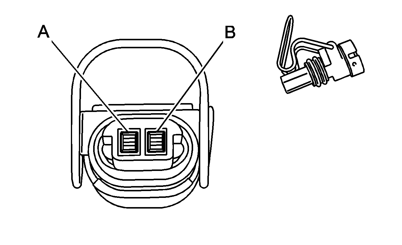
Pin | Wire Color | Circuit No. | Function | ||||
A | D-BU | 5930 | Turbocharger Vane Position Control Solenoid Valve | ||||
B | WH | 5931 | Low Reference | ||||
| |||||||
|---|---|---|---|---|---|---|---|
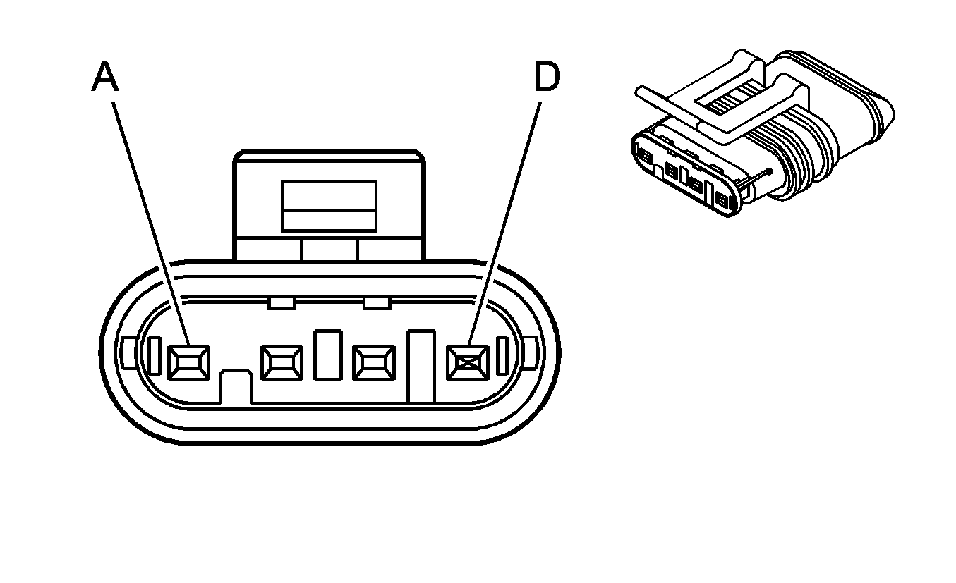
Connector Part Information |
| ||||||
Pin | Wire Color | Circuit No. | Function | ||||
A | OG/BK | 5929 | 5-Volt Reference | ||||
B | TN | 5928 | Low Reference | ||||
C | YE | 5947 | Turbocharger Vane Position Sensor Signal | ||||
D | -- | -- | Not Used | ||||
