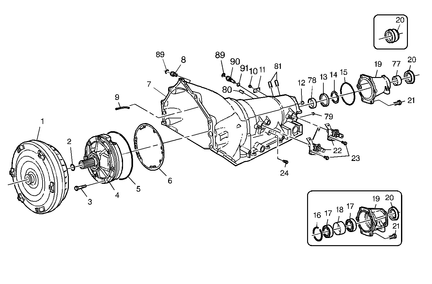
| Figure 1: |
Case and Associated Parts (1 of 3)
|
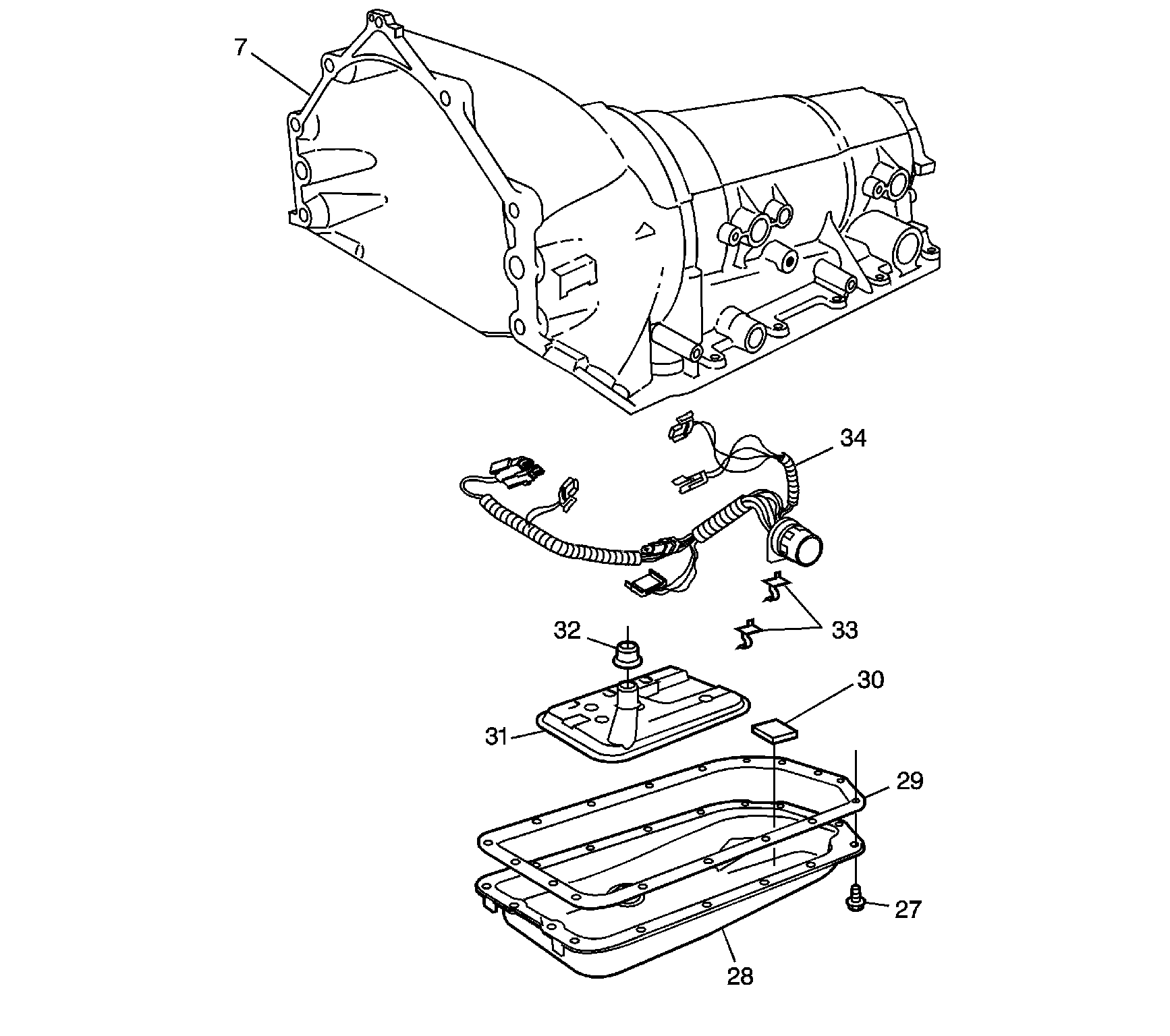
| Figure 2: |
Case and Associated Parts (2 of 3)
|
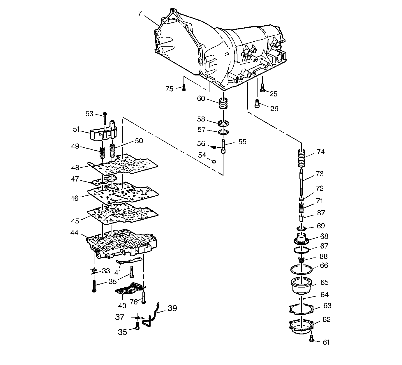
| Figure 3: |
Case and Associated Parts (3 of 3)
|
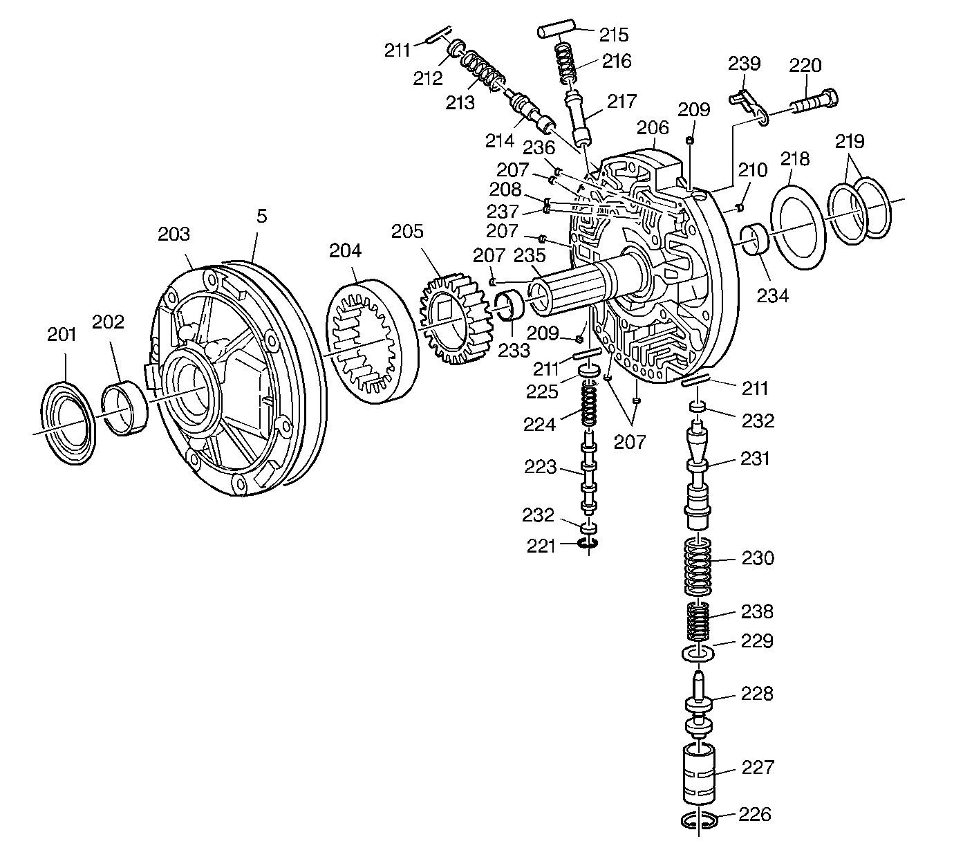
| Figure 4: |
Oil Pump Assembly
|
| Figure 5: |
Control Valve Body Assembly (1 of 2)
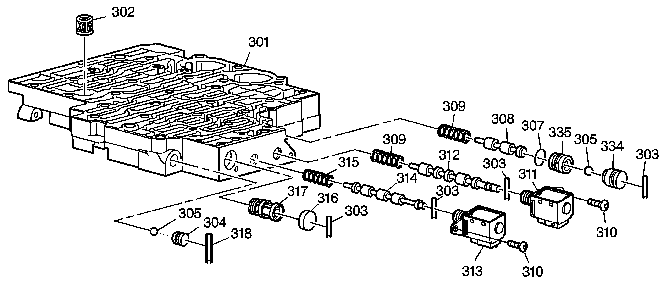
|
| Figure 6: |
Control Valve Body Assembly (2 of 2)
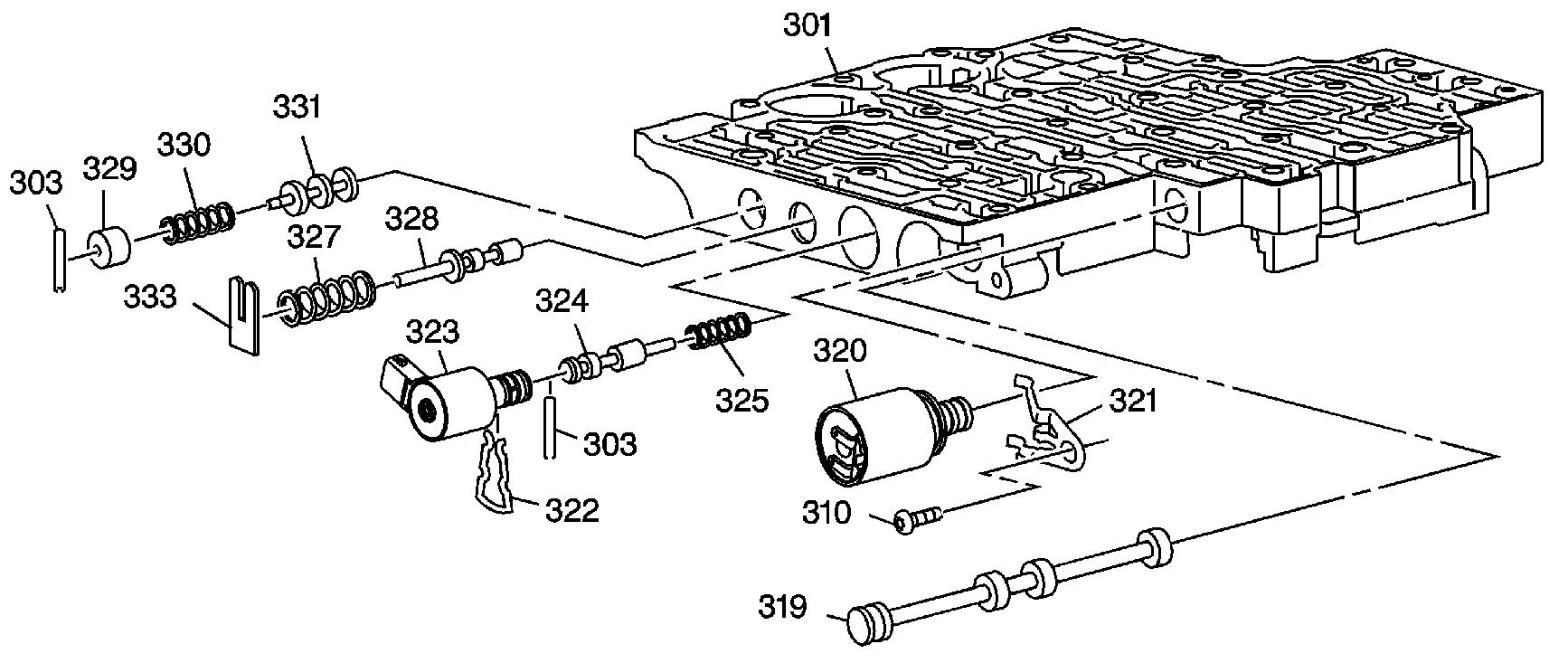
|
| Figure 7: |
Accumulator Assembly
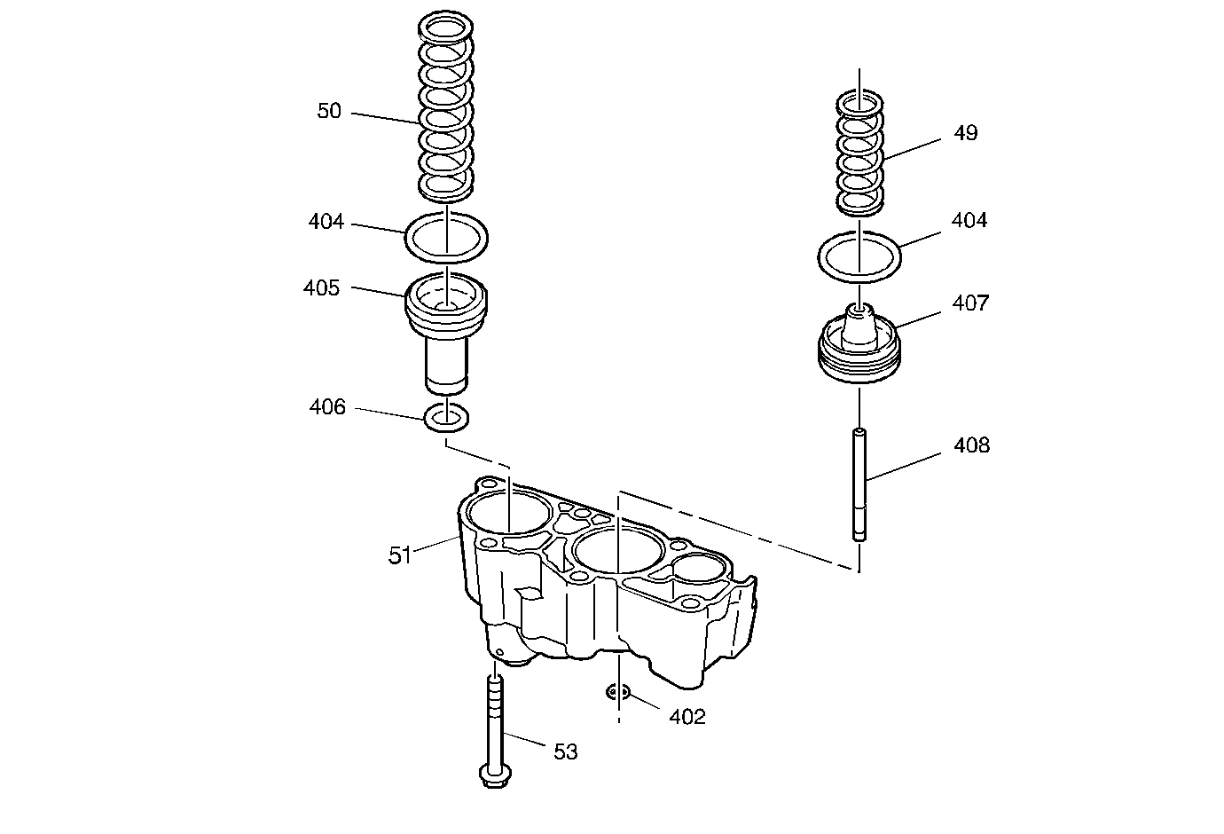
|
| Figure 8: |
Overrun Clutch Assembly
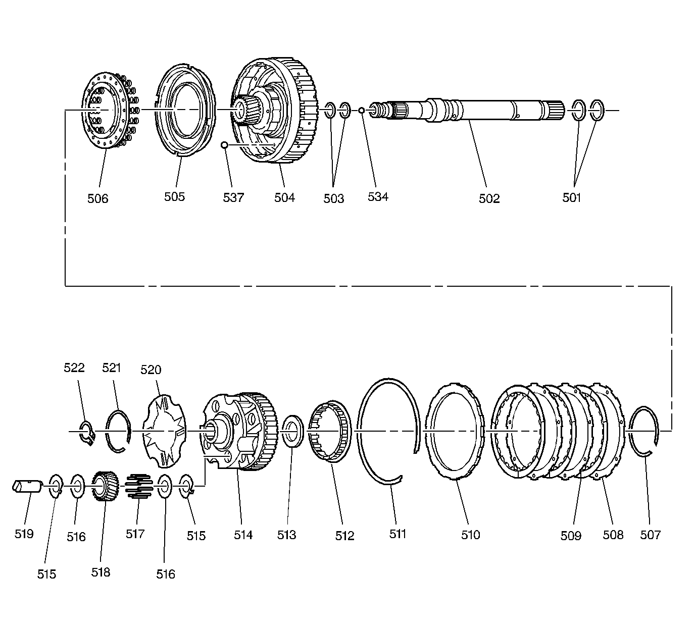
|
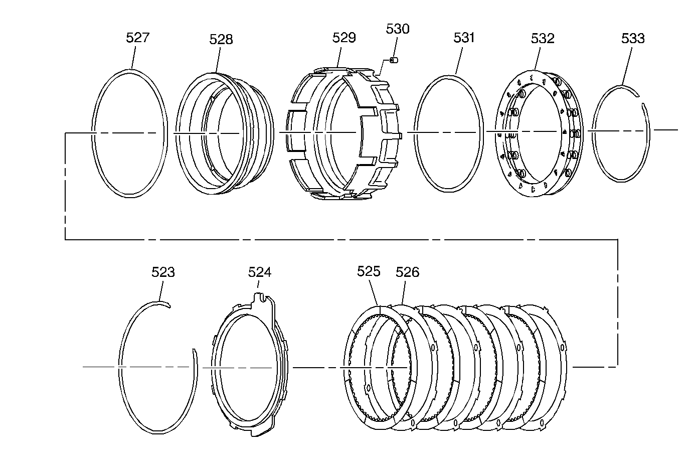
| Figure 9: |
Fourth Clutch Assembly
|
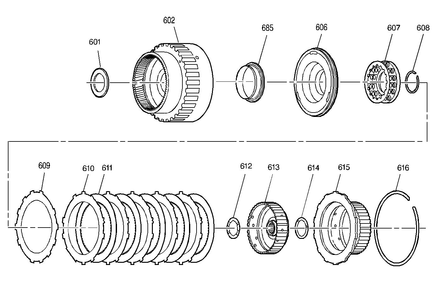
| Figure 10: |
Forward Clutch Assembly
|
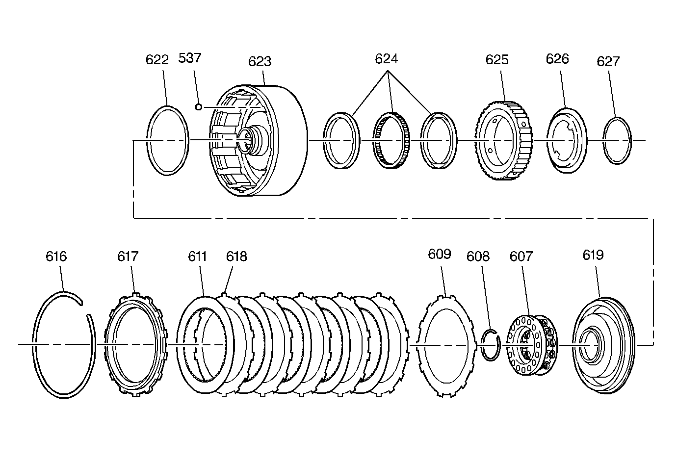
| Figure 11: |
Direct Clutch and Intermediate Sprag Assembly
|
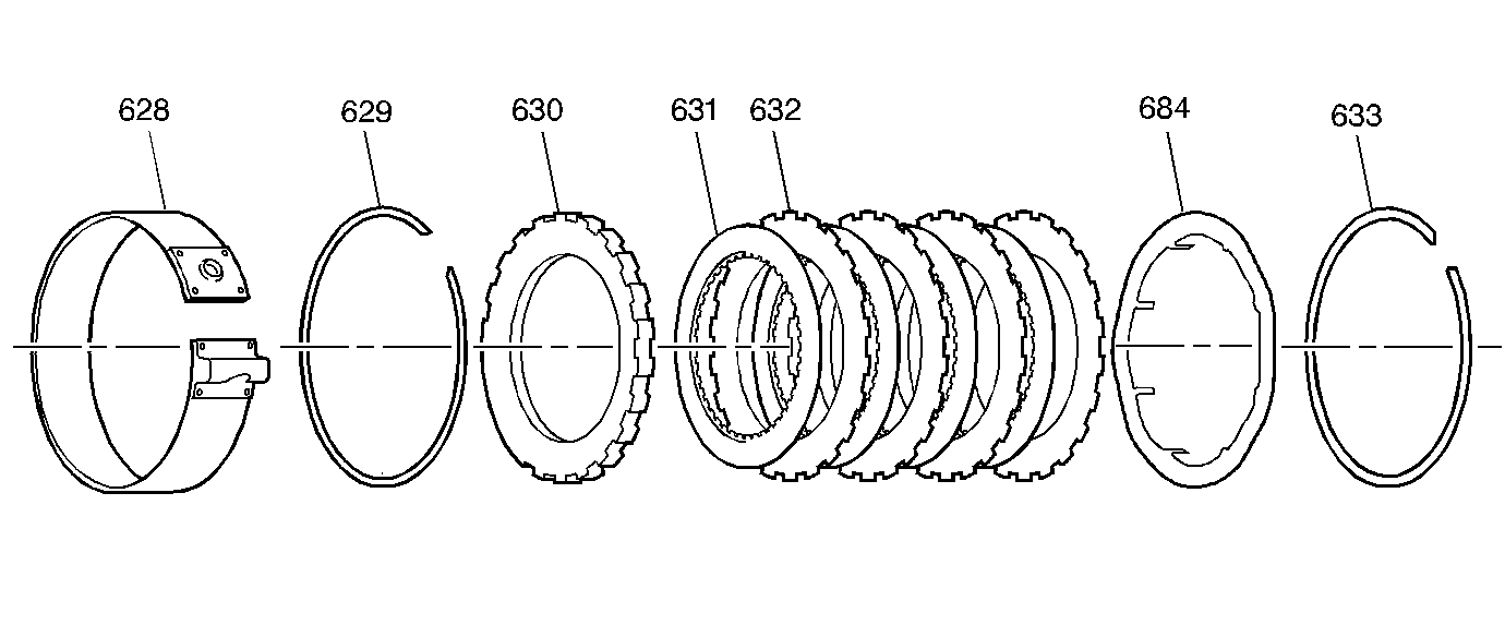
| Figure 12: |
Intermediate Clutch Plates and Manual 2-1 Band Assembly
|
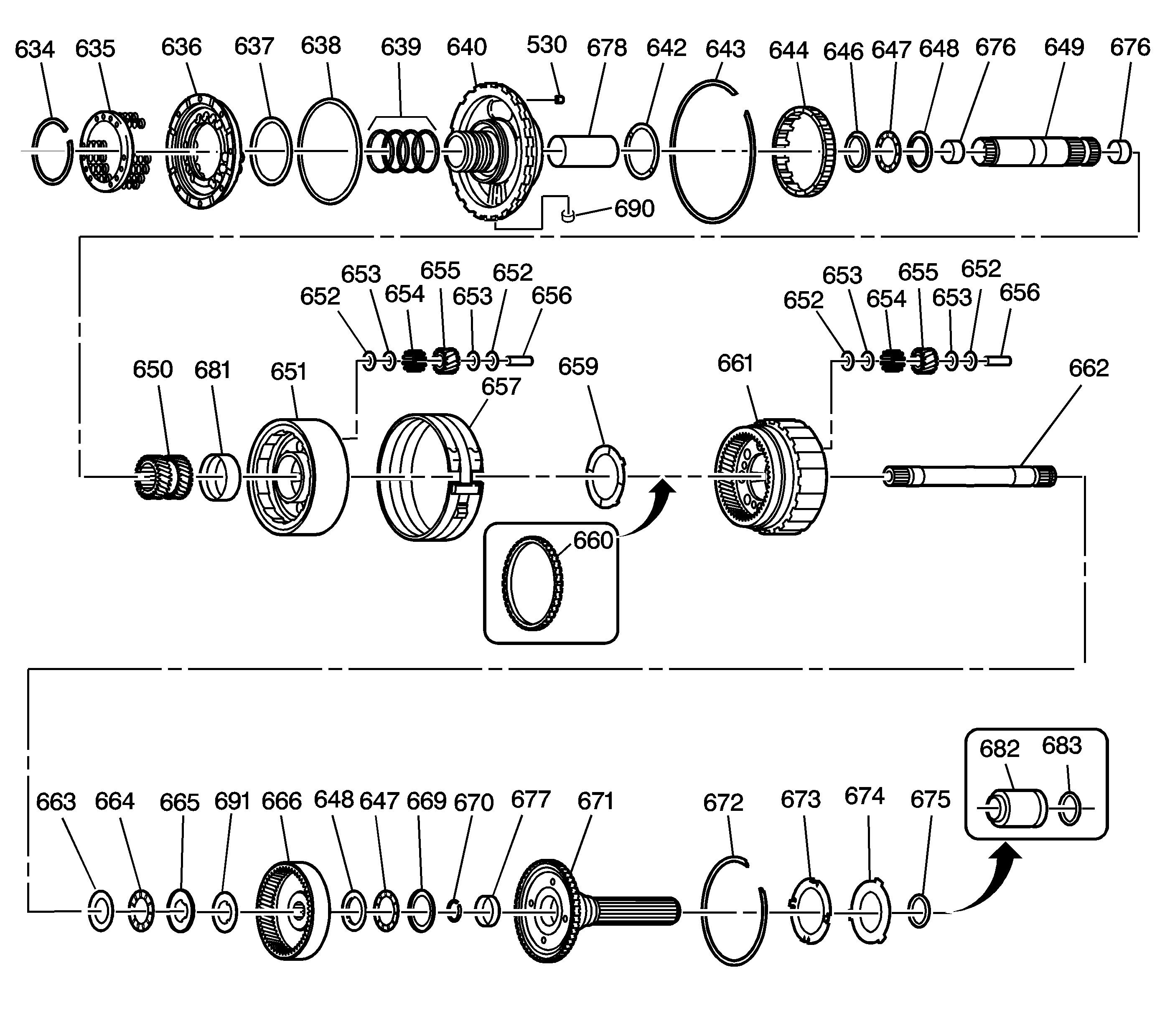
| Figure 13: |
Center Support and Gear Unit Assembly
|
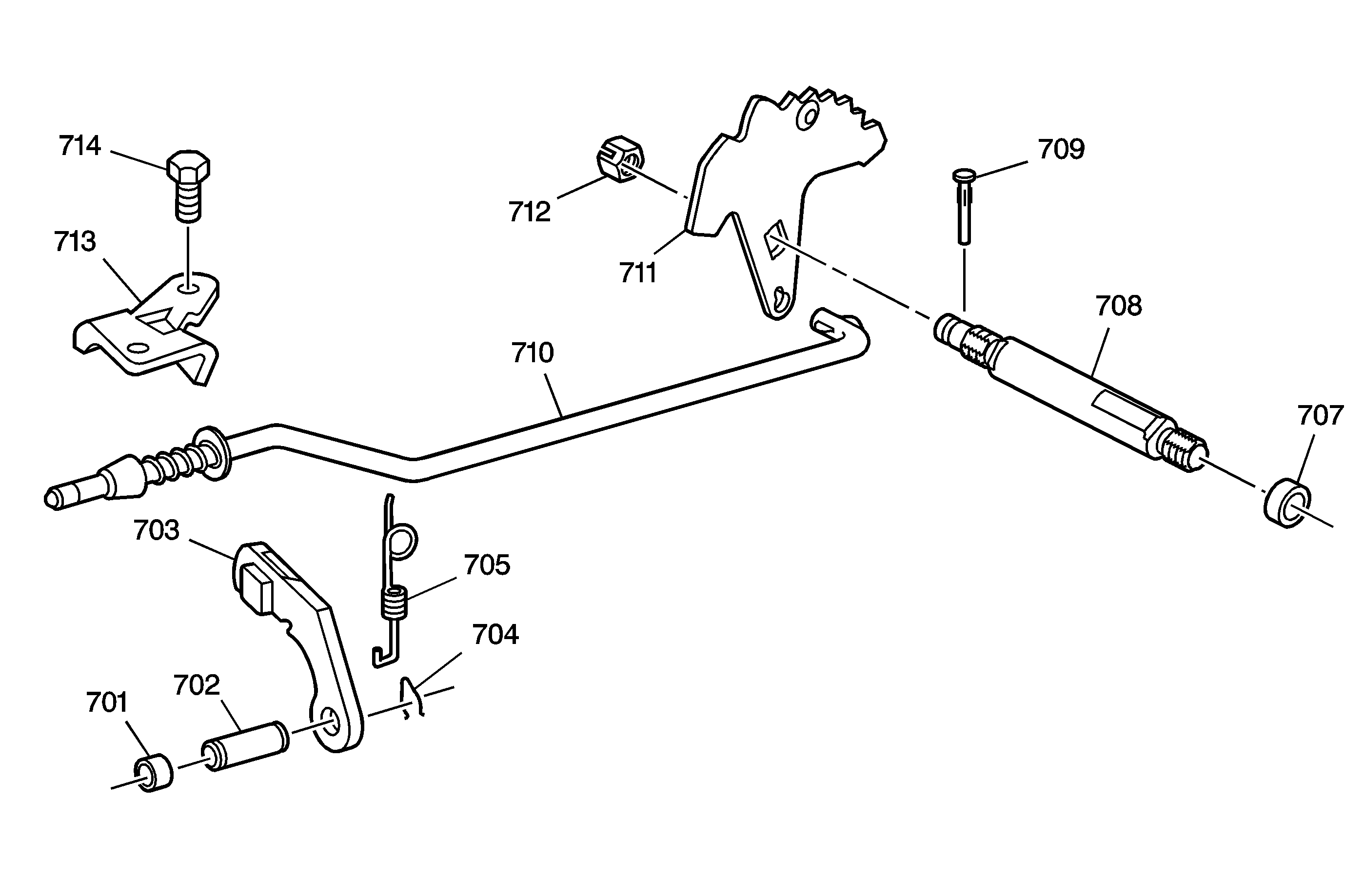
| Figure 14: |
Parking Lock and Actuator Assembly
|
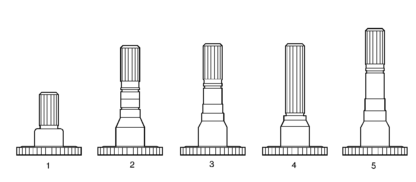
| Figure 15: |
Output Shaft Identification
|
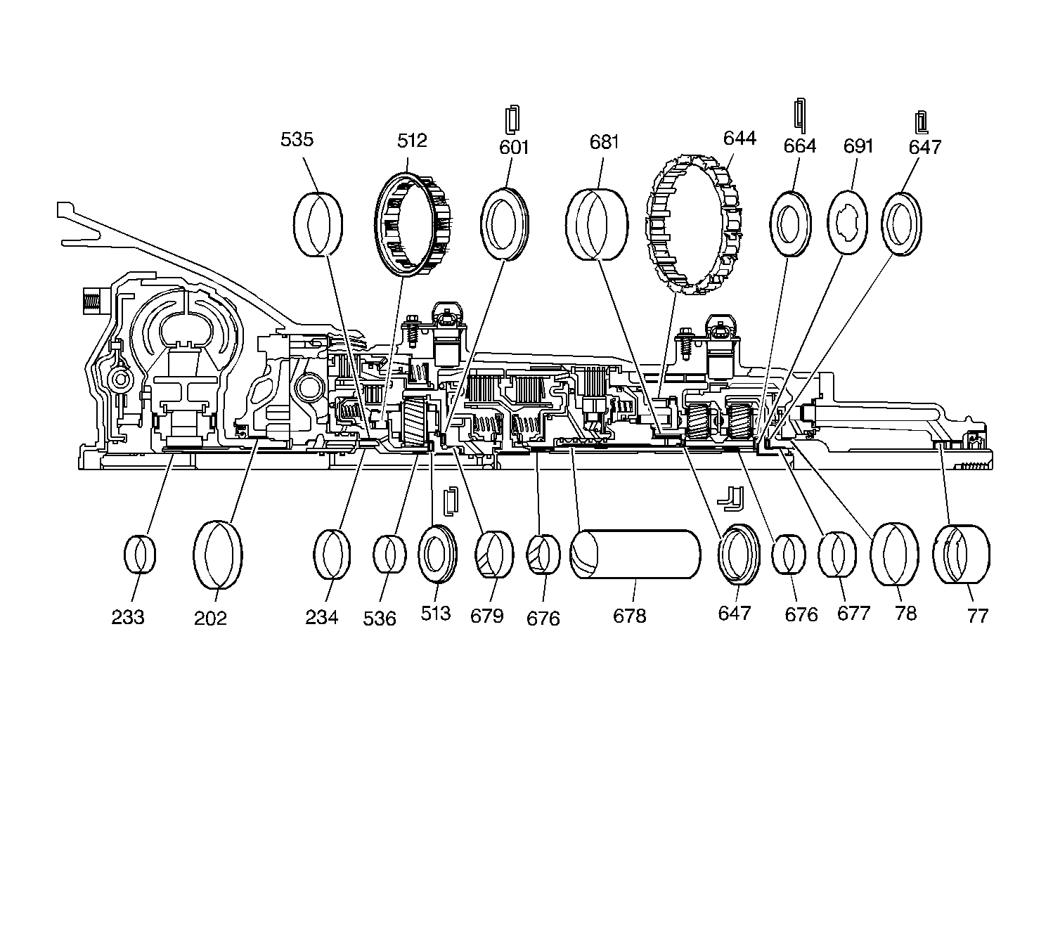
| Figure 16: |
Bushing and Bearing Locations
|
| Figure 17: |
Seals
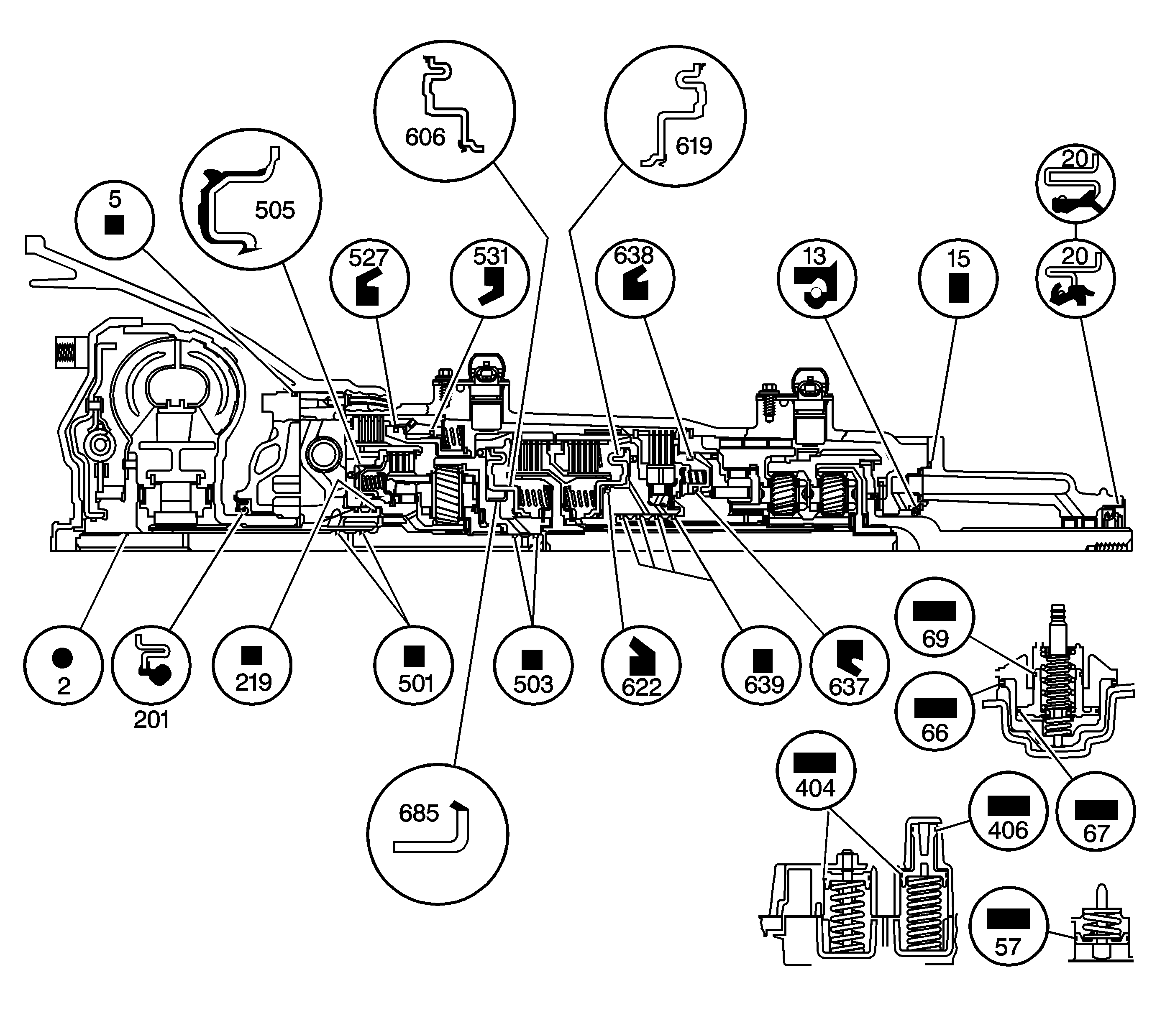
|
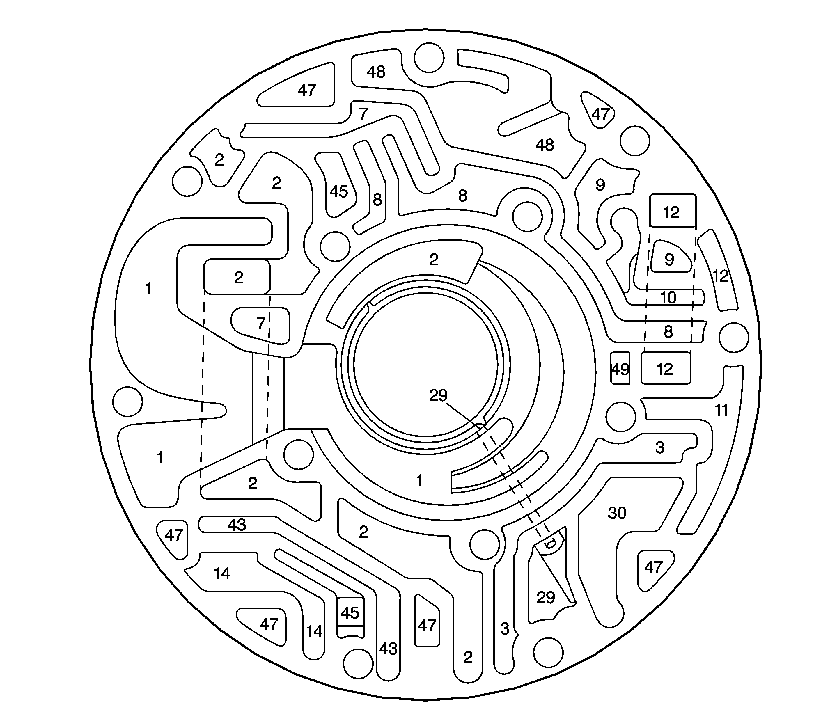
| Figure 18: |
Pump Body Fluid Passages (Pump Cover Side)
|
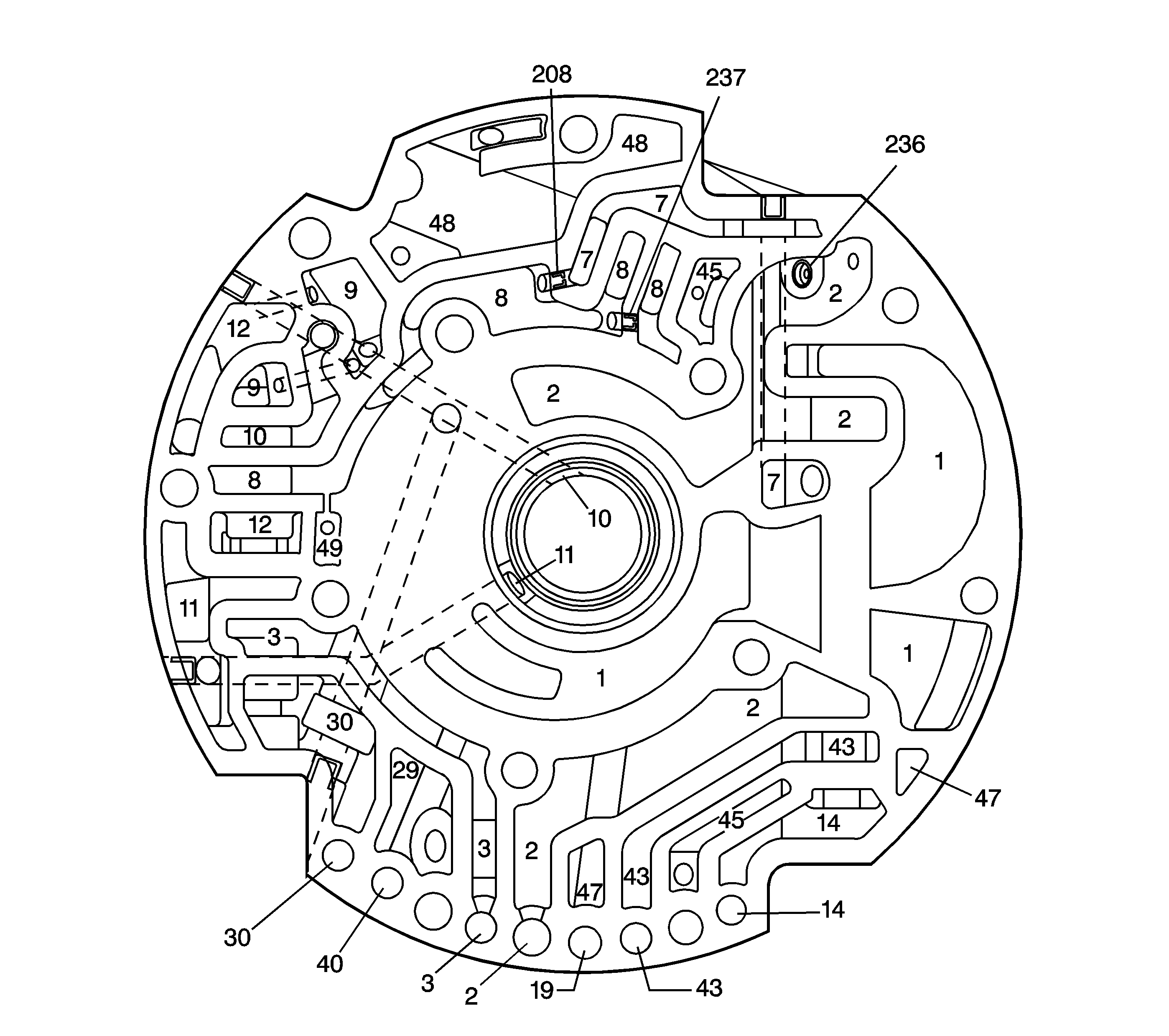
| Figure 19: |
Pump Cover Fluid Passages (Pump Body Side)
|
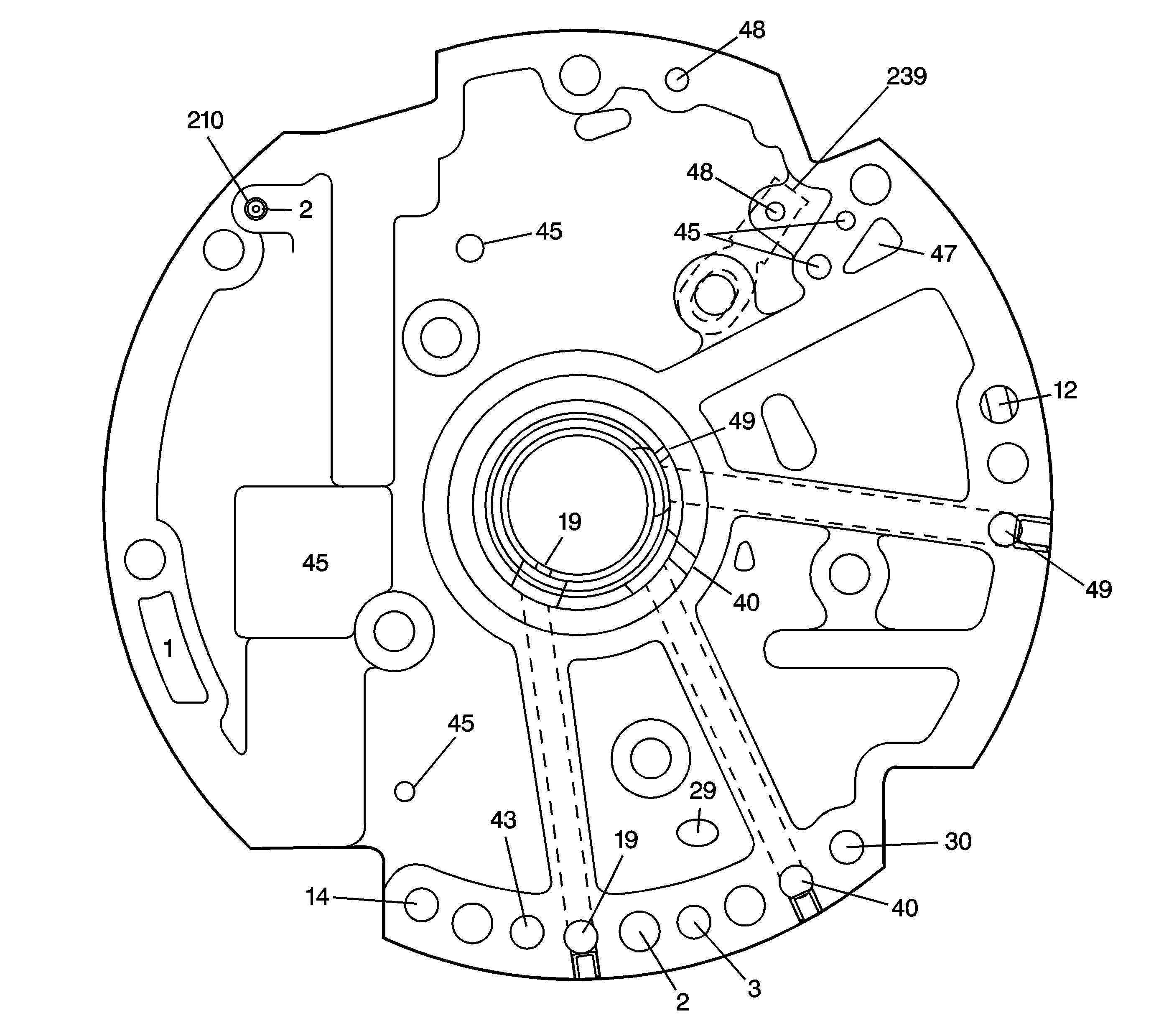
| Figure 20: |
Pump Cover Fluid Passages (Case Side)
|
| Figure 21: |
Case Fluid Passages (Pump Cover Side)

|
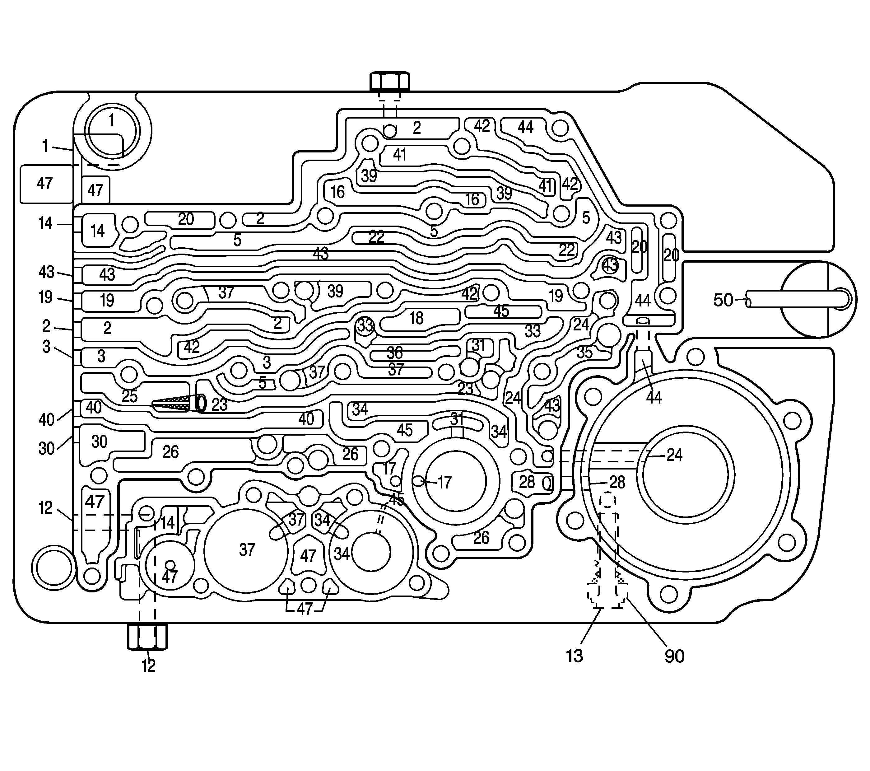
| Figure 22: |
Case Fluid Passages (Control Valve Body Side)
|
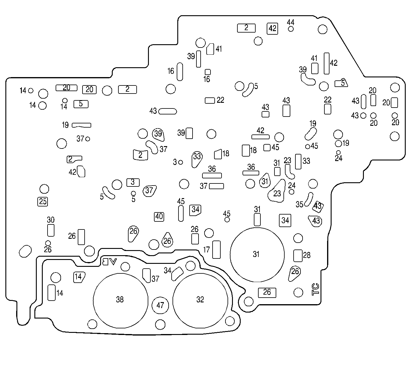
| Figure 23: |
Spacer Plate to Case Gasket with Accumulator Housing Gasket
|
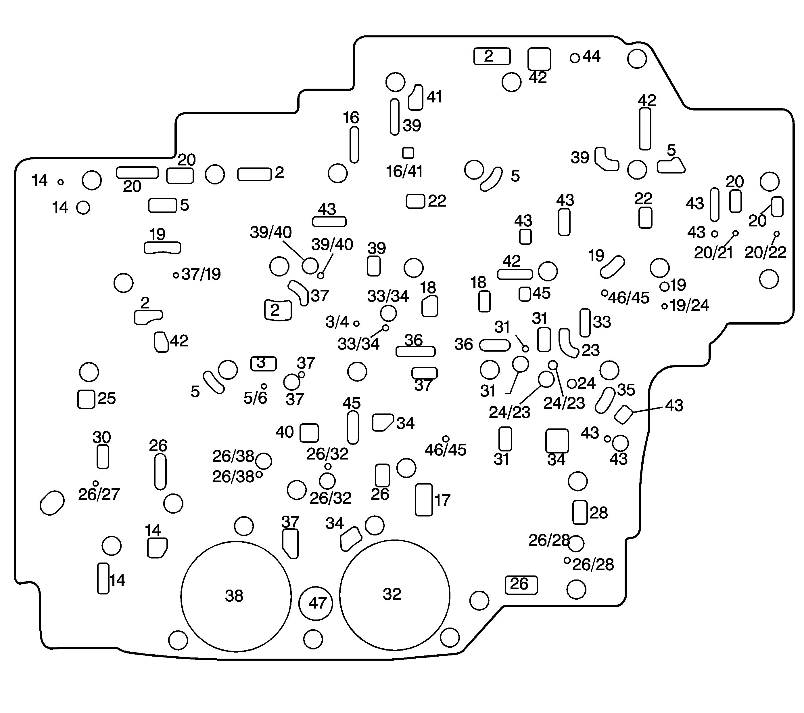
| Figure 24: |
Spacer Plate
|
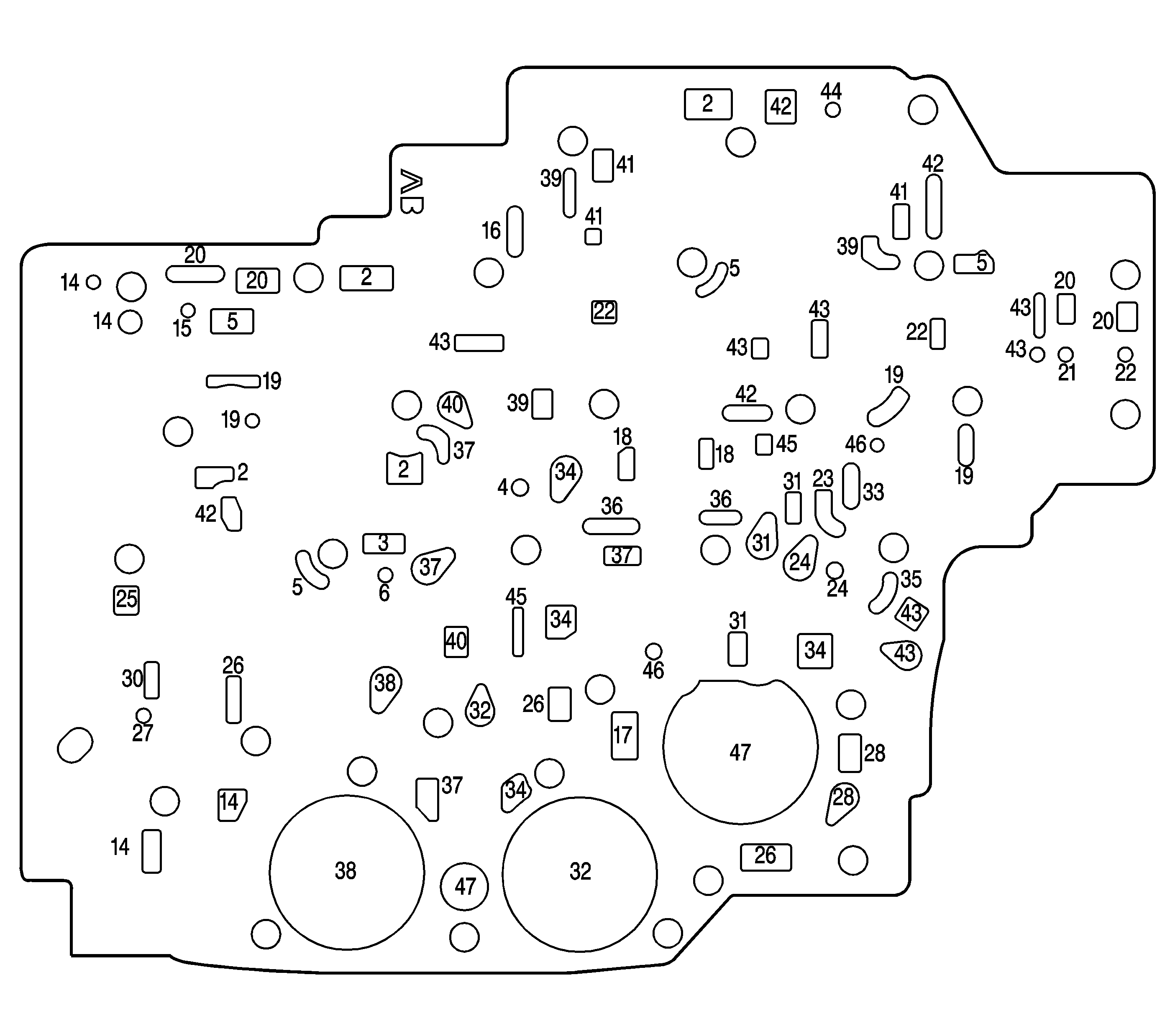
| Figure 25: |
Spacer Plate to Control Valve Body Gasket
|
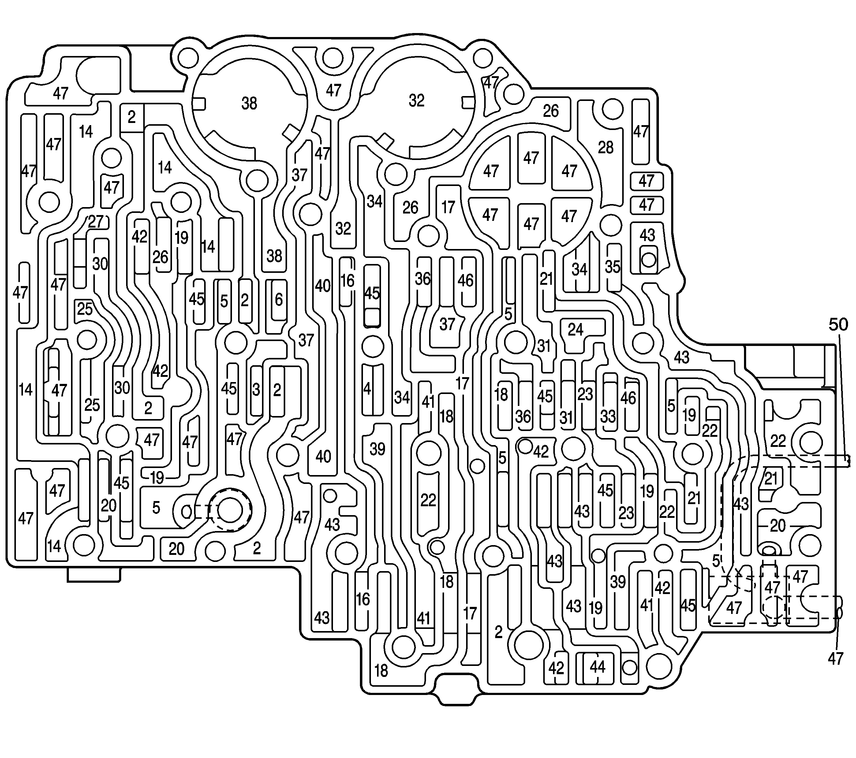
| Figure 26: |
Control Valve Body Fluid Passages (Case Side)
|