Tools Required
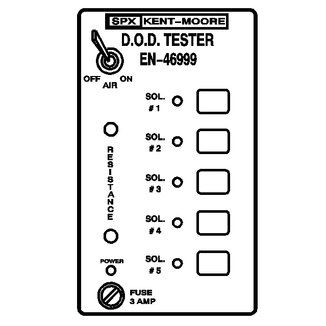
| • | EN-46999
Active Fuel Management Tester |
| • | EN-46999-1
Active Fuel Management Tester Air Adapter |
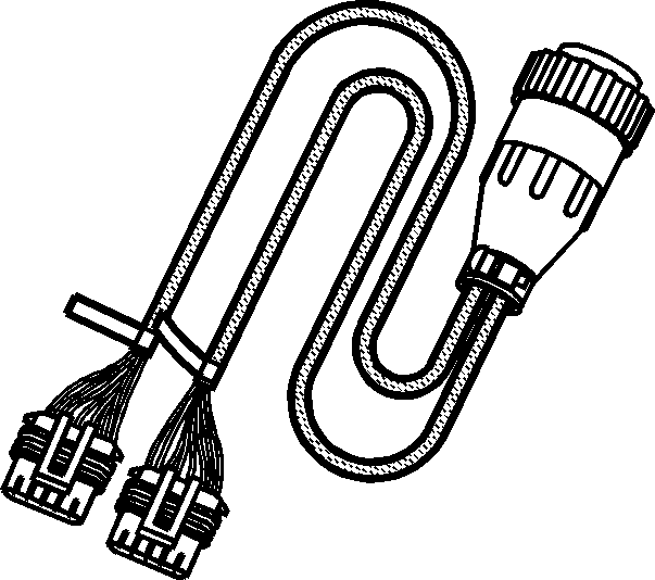
| • | EN-46999-5
Active Fuel Management Tester Harness - Small Block V8 |
Important:
| • | Active Fuel Management Valve Lifter Oil Manifold Diagnosis and Testing is applicable for RPO LC9/LY5/LMG/L76/L92. |
| • | Active fuel management hardware is present in first design L92 engines. The system is inactive for the 2007 model year. |
| • | A minimum shop air source of 206 kPa (30 psi) is required for manifold testing. |
| • | A water bleed is located on the side of the
EN-46999
. Occasionally, depress the valve in order to remove excess water from the tool. |
The manifold bench test provides a maximum 206 kPa (30 psi) of filtered shop air to the manifold and will test each solenoid/valve for the following conditions:
| • | A stuck open condition - constant air flow |
| • | A stuck closed condition - no air flow |
| • | A flow restriction within the manifold |
- Individually depress each of the buttons 1-4 on the
EN-46999
in order to activate each of the solenoid/valves. When activating each solenoid/valve, a loud click should be heard from
the solenoid and an increased amount of air will exit the outlet ports.
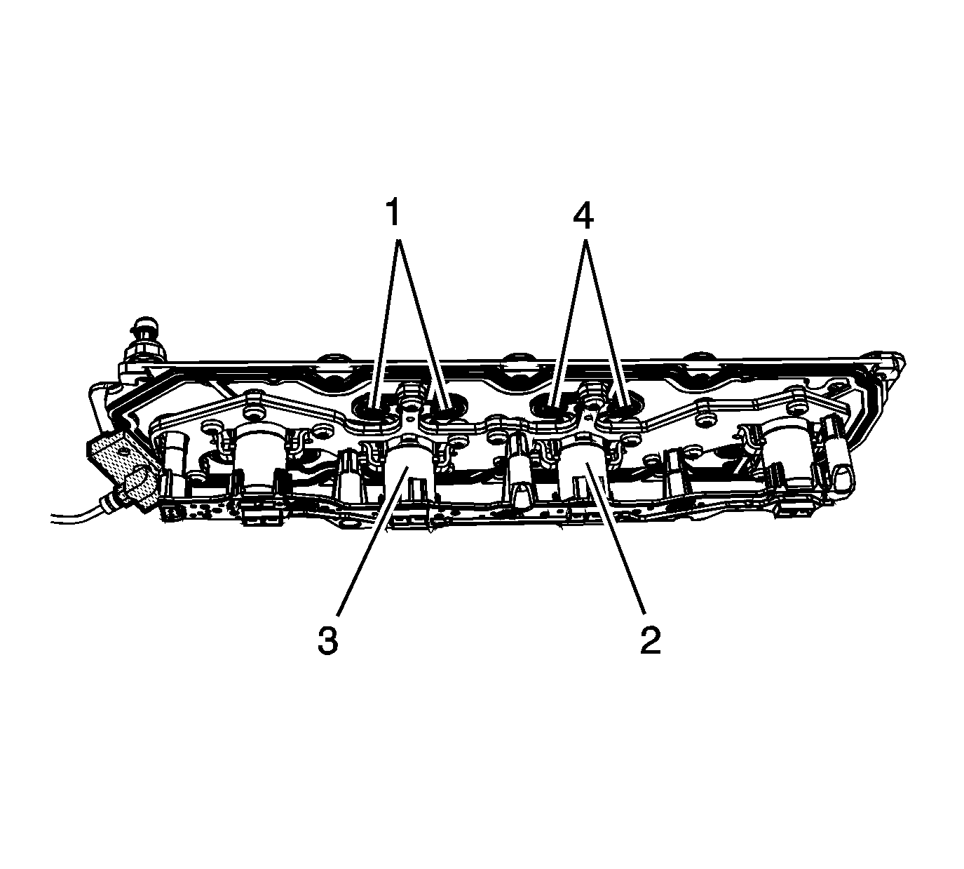
| • | Button 1 will energize the solenoid/valve 1 for engine cylinder number 1. |
| • | Button 2 will energize the solenoid/valve 2 for engine cylinder number 4. |
| • | Button 3 will energize the solenoid/valve 3 for engine cylinder number 6. |
| • | Button 4 will energize the solenoid/valve 4 for engine cylinder number 7. |
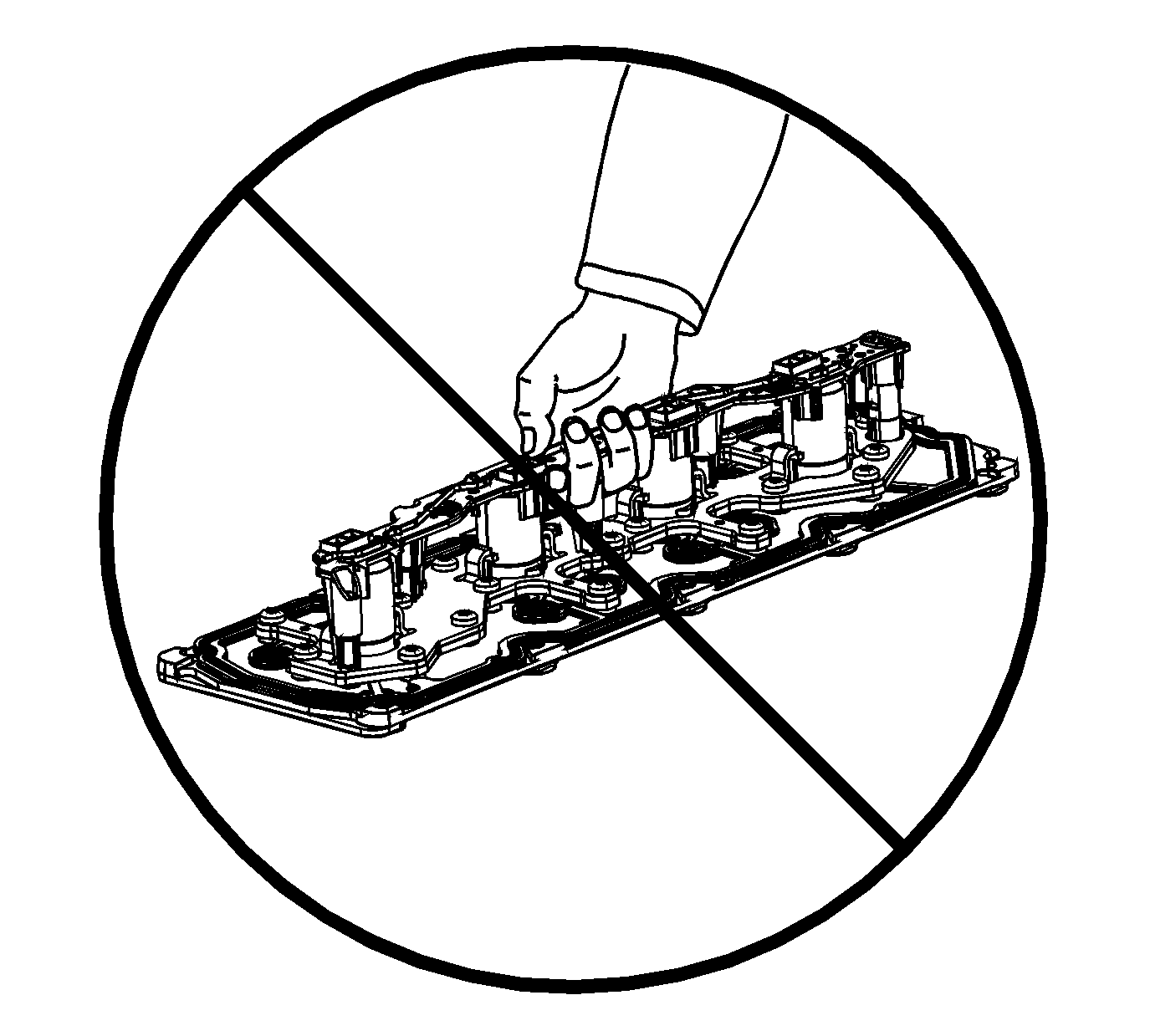
- Do not lift the manifold assembly by
the electrical lead frame.
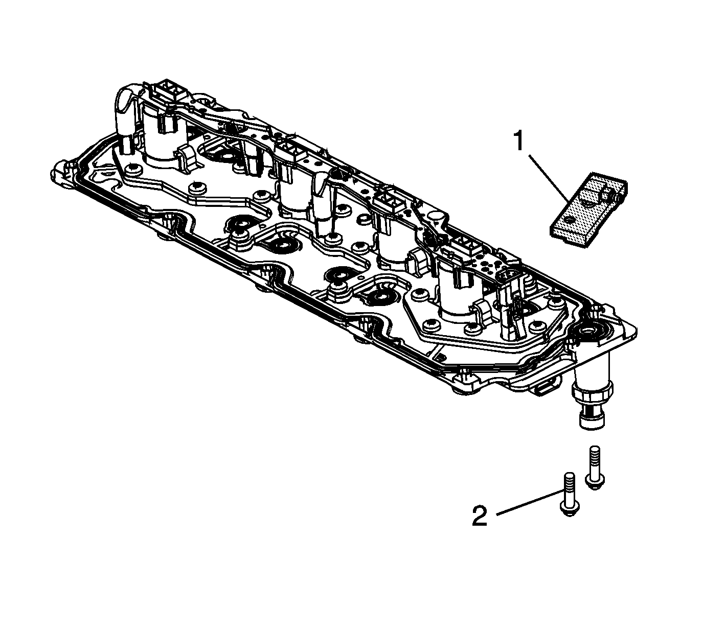
- Install the
EN-46999-1
(1)
to the manifold.
Notice: Refer to Fastener Notice in the Preface section.
- Install 2 of the manifold bolts (2) to the
EN-46999-1
.
Tighten
Tighten the bolts to 25 N·m (18 lb ft).
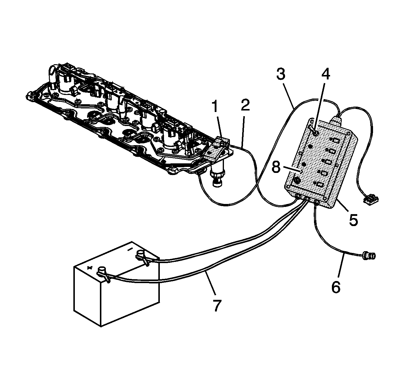
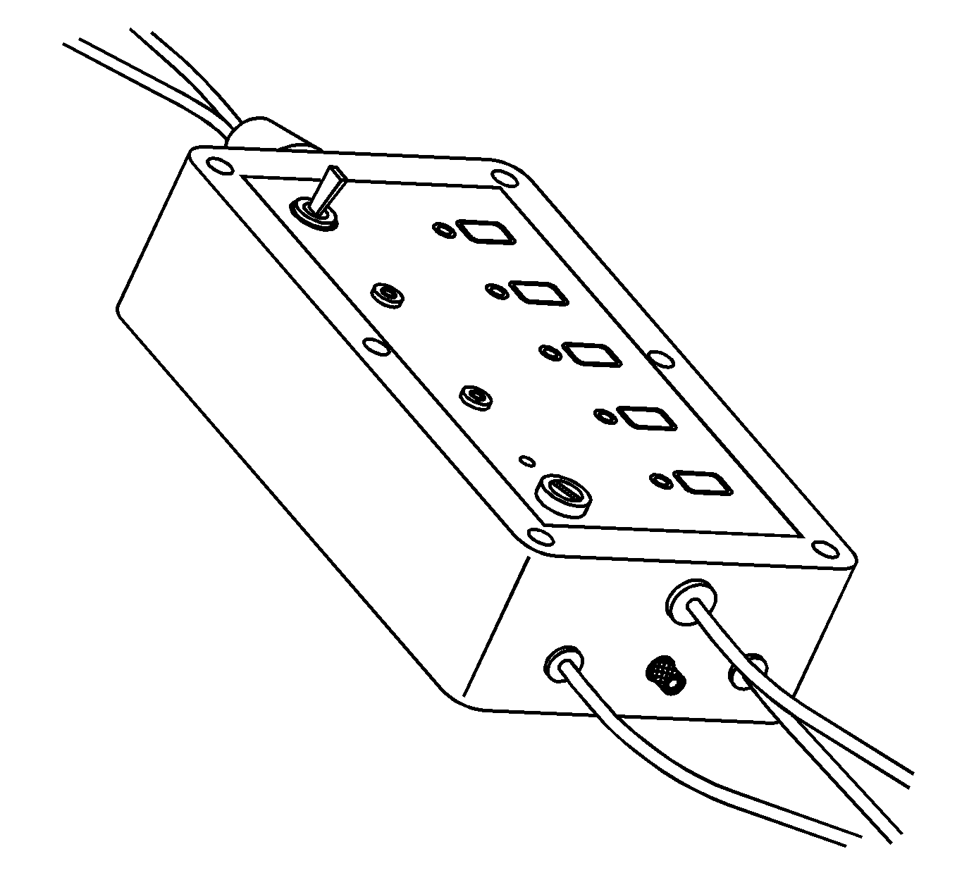
- Connect the air out hose (2) of the
EN-46999
(5) to the
EN-46999-1
(1). Verify the air supply switch (4) is in the off position.
- Connect the air in hose (6) of the
EN-46999
(5) to a shop air source.
- Connect the 12 volt power supply connectors (7) of the
EN-46999
(5) to a 12 volt power supply. Verify the Power light (8) on the tool is illuminated. If the
light on the tool is not illuminated when connected to a 12 volt power supply, test and/or replace the 3 amp fuse.
- Connect the
EN-46999-5
power cable (3) to the electrical connector of the manifold.
- Turn the air supply switch of the
EN-46999
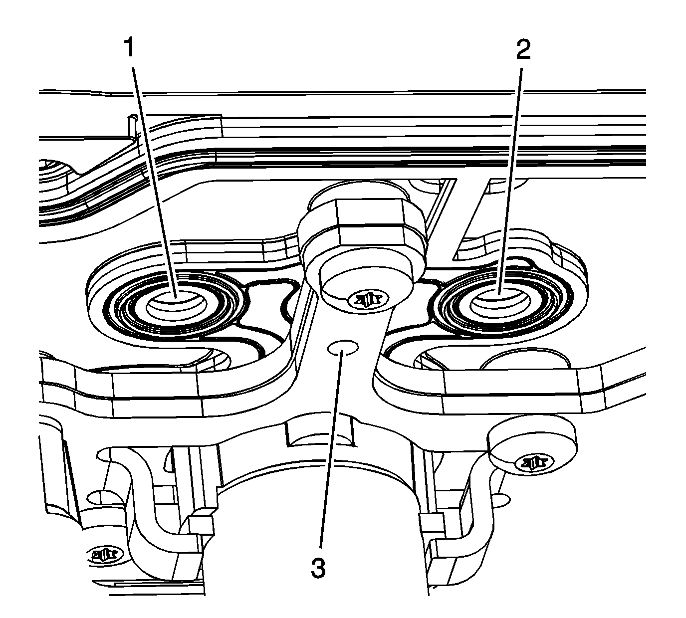
to the ON position. With the air supply connected to the manifold assembly and the solenoid/valves in the closed position, a limited amount of air will exit each of the bleed holes (3) and outlet ports (1,
2) of the manifold.

Important: The manifold must be tested in the proper position to ensure the solenoid/valves operate as designed.
- Position the manifold assembly onto a bench at a 45 degree angle in order to test solenoid/valves 1 and 4.
- Depress button number 1 on the tool to activate solenoid/valve 1. With button 1 depressed, the solenoid/valve (1) should open, allowing an increased amount of air to exit the outlet ports (2) of the manifold.
- Depress button number 4 on the tool to activate solenoid/valve 4. With button 4 depressed, the solenoid/valve (4) should open, allowing an increased amount of air to exit the outlet ports (3) of the manifold.
- Reposition the manifold assembly onto a bench at a 45 degree angle in order
to test solenoid/valves 2 and 3.
- Depress button number 2 on the tool to activate solenoid/valve 2. With button 2 depressed, the solenoid/valve (2) should open, allowing an increased amount of air to exit the outlet ports (4) of the manifold.
- Depress button number 3 on the tool to activate solenoid/valve 3. With button 3 depressed, the solenoid/valve (3) should open, allowing an increased amount of air to exit the outlet ports (1) of the manifold.
- When the test is completed, turn the air source switch on the
EN-46999
to the off position and disconnect the tool from the 12 volt power supply, shop air source and manifold assembly.
- If after testing, it has been determined that one or more of the solenoid/valves is not functioning properly, replace the manifold as an assembly.
- If after testing, it has been determined that the solenoid/valves are functioning properly, replace the valve lifters as required. Both intake and exhaust lifters should be replaced in pairs.
