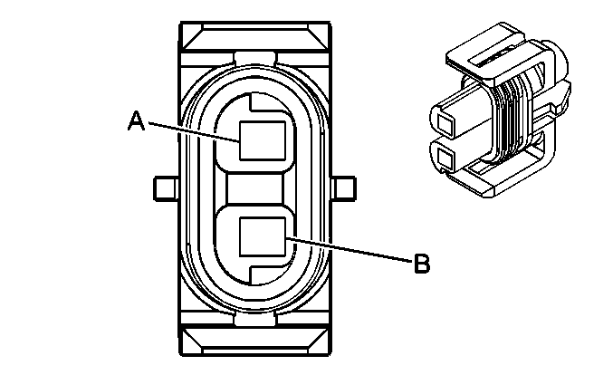
| |||||||
|---|---|---|---|---|---|---|---|
Connector Part Information |
| ||||||
Pin | Wire Color | Circuit No. | Function | ||||
A | BLK | 550 | Ground | ||||
B | DK GRN | 59 | A/C Compressor Clutch Supply Voltage | ||||
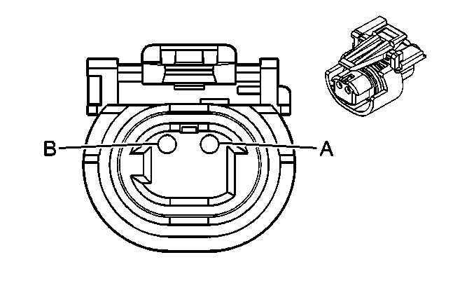
| |||||||
|---|---|---|---|---|---|---|---|
Connector Part Information |
| ||||||
Pin | Wire Color | Circuit No. | Function | ||||
A | LT BLU | 203 | A/C Request Signal | ||||
B | DK GRN/WHT | 2523 | A/C Request Signal | ||||
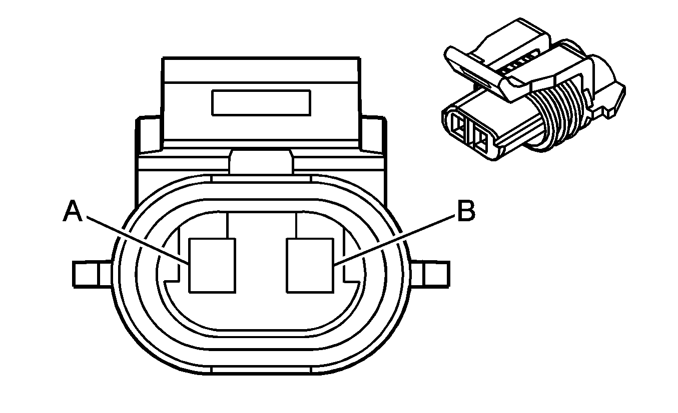
| |||||||
|---|---|---|---|---|---|---|---|
Connector Part Information |
| ||||||
Pin | Wire Color | Circuit No. | Function | ||||
A | DK GRN | 603 | A/C Low Pressure Switch Signal | ||||
B | BLK | 550 | Ground | ||||
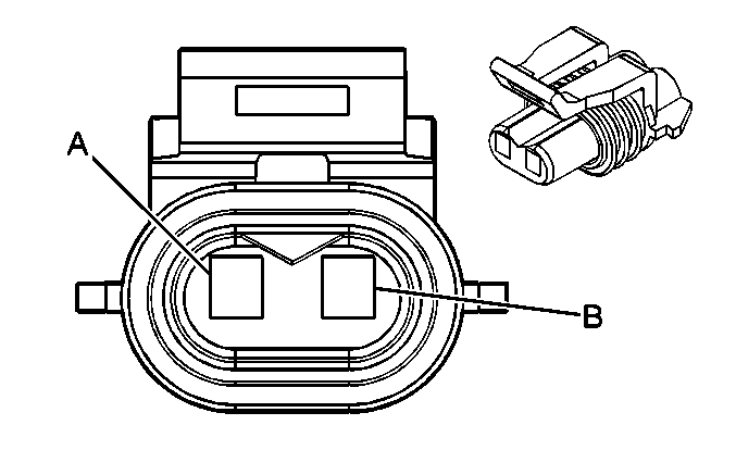
| |||||||
|---|---|---|---|---|---|---|---|
Connector Part Information |
| ||||||
Pin | Wire Color | Circuit No. | Function | ||||
A | DK BLU | 604 | A/C High Pressure Recirculation Switch Signal | ||||
B | BLK | 150 | Ground | ||||
| |||||||
|---|---|---|---|---|---|---|---|
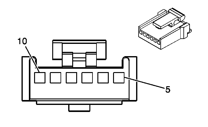
Connector Part Information |
| ||||||
Pin | Wire Color | Circuit No. | Function | ||||
5 | BRN | 341 | Ignition 3 Voltage | ||||
6 | DK BLU | 1199 | Auxiliary Air Temperature Door Control | ||||
7 | BLK | 2450 | Ground | ||||
8 | -- | -- | Not Used | ||||
9 | LT BLU | 733 | Auxiliary Air Temperature Door Position Signal | ||||
10 | GRY | 598 | 5 Volt Reference | ||||

| |||||||
|---|---|---|---|---|---|---|---|
Connector Part Information |
| ||||||
Pin | Wire Color | Circuit No. | Function | ||||
5 | BRN | 541 | Ignition 3 Voltage | ||||
6 | WHT/BLK | 1236 | Air Temperature Door Control - Auxiliary | ||||
7 | GRY/BLK | 1798 | Ground | ||||
8 | -- | -- | Not Used | ||||
9 | DK BLU | 1646 | Air Temperature Door Position Signal - Auxiliary | ||||
10 | GRY | 598 | 5 Volt Reference | ||||

| |||||||
|---|---|---|---|---|---|---|---|
Connector Part Information |
| ||||||
Pin | Wire Color | Circuit No. | Function | ||||
5-6 | -- | -- | Not Used | ||||
7 | BLK | 1450 | Ground | ||||
8 | WHT | 454 | Mode Door Control - Auxiliary | ||||
9 | -- | -- | Not Used | ||||
10 | BRN | 541 | Ignition 3 Voltage | ||||
| |||||||
|---|---|---|---|---|---|---|---|
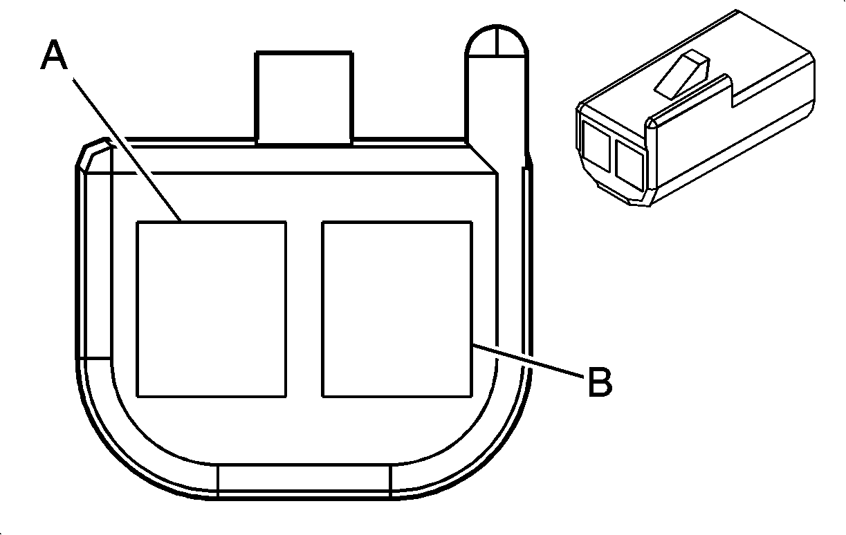
Connector Part Information |
| ||||||
Pin | Wire Color | Circuit No. | Function | ||||
A | LT GRN | 404 | Upper Air Temperature Sensor Signal | ||||
B | BRN | 718 | Low Reference | ||||

| |||||||
|---|---|---|---|---|---|---|---|
Connector Part Information |
| ||||||
Pin | Wire Color | Circuit No. | Function | ||||
A | TAN | 517 | Upper Auxiliary Air Temperature Sensor Signal | ||||
B | BLK | 808 | Low Reference | ||||

| |||||||
|---|---|---|---|---|---|---|---|
Connector Part Information |
| ||||||
Pin | Wire Color | Circuit No. | Function | ||||
A | LT GRN | 405 | Lower Air Temperature Sensor Signal | ||||
B | BRN | 718 | Low Reference | ||||

| |||||||
|---|---|---|---|---|---|---|---|
Connector Part Information |
| ||||||
Pin | Wire Color | Circuit No. | Function | ||||
A | BLK | 520 | Lower Auxiliary Air Temperature Sensor Signal | ||||
B | BRN | 808 | Low Reference | ||||
| |||||||
|---|---|---|---|---|---|---|---|
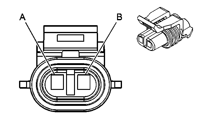
Connector Part Information |
| ||||||
Pin | Wire Color | Circuit No. | Function | ||||
A | LT GRN/BLK | 735 | Ambient Air Temperature Sensor Signal | ||||
B | BRN | 718 | Low Reference | ||||
| |||||||
|---|---|---|---|---|---|---|---|
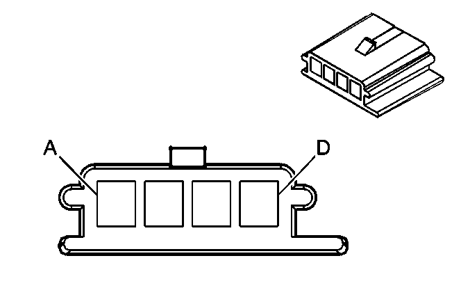
Connector Part Information |
| ||||||
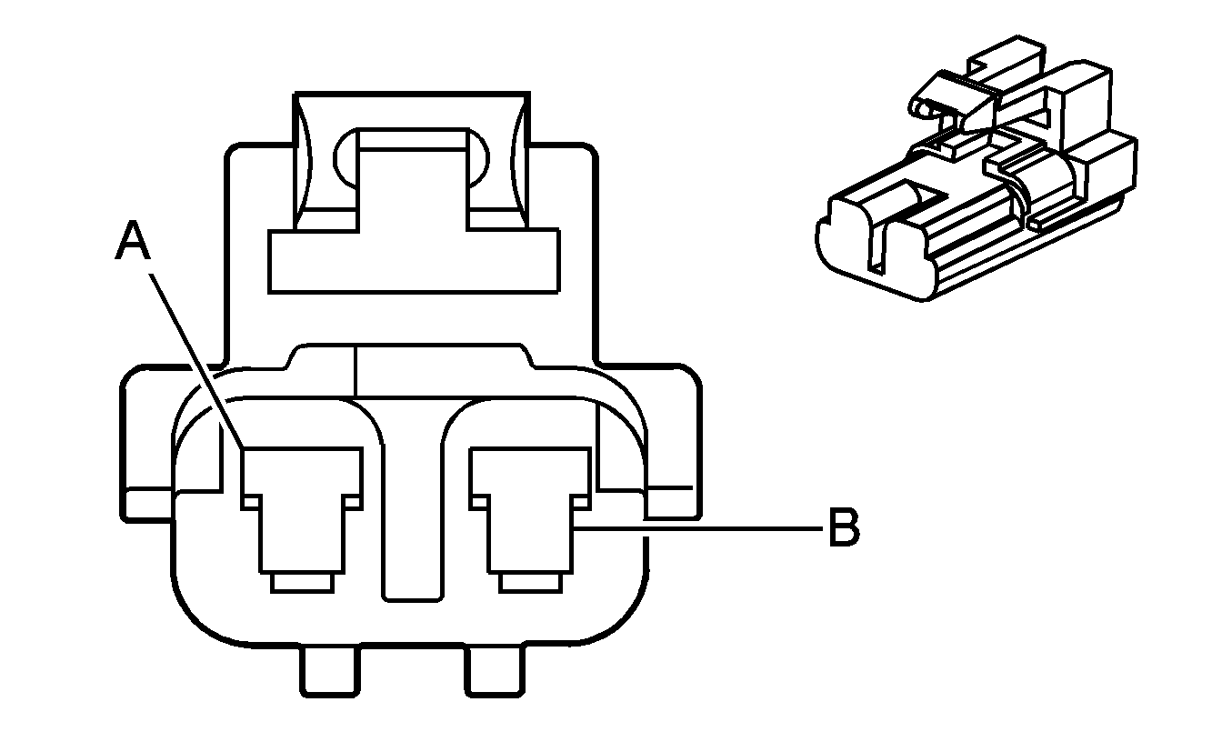
Pin | Wire Color | Circuit No. | Function | ||||
A | DK GRN | 734 | Inside Air Temperature Sensor Signal | ||||
B | PNK | 39 | Ignition 1 Voltage | ||||
C | BLK | 1850 | Ground | ||||
D | BRN | 718 | Low Reference | ||||
| |||||||
|---|---|---|---|---|---|---|---|
Connector Part Information |
| ||||||
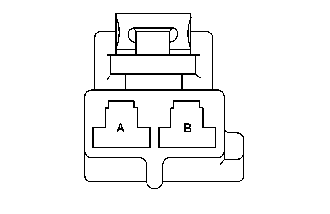
Pin | Wire Color | Circuit No. | Function | ||||
A | PPL | 65 | Blower Motor Supply Voltage | ||||
B | BLK | 1050 | Ground | ||||
| |||||||
|---|---|---|---|---|---|---|---|
Connector Part Information |
| ||||||
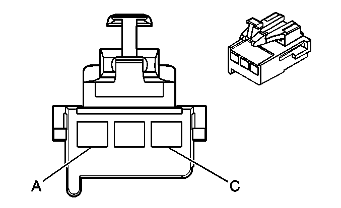
Pin | Wire Color | Circuit No. | Function | ||||
A | BLK | -- | Ground | ||||
B | PPL | -- | Blower Motor - Auxiliary Supply Voltage | ||||
| |||||||
|---|---|---|---|---|---|---|---|
Connector Part Information |
| ||||||
Pin | Wire Color | Circuit No. | Function | ||||
A | BLK | 1450 | Ground | ||||
B | PPL | 374 | Auxiliary Blower Motor Speed Control | ||||
C | ORN | 1740 | Battery Positive Voltage | ||||

| |||||||
|---|---|---|---|---|---|---|---|
Connector Part Information |
| ||||||
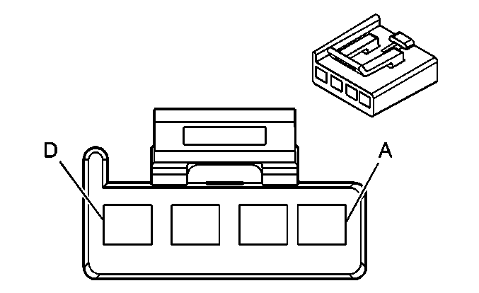
Pin | Wire Color | Circuit No. | Function | ||||
A | DK BLU | 1926 | Auxiliary Blower Motor Low Speed Control | ||||
B | RED | 1925 | Auxiliary Blower Motor Medium Speed Control | ||||
C | WHT | 1924 | Auxiliary Blower Motor High Speed Control | ||||
| |||||||
|---|---|---|---|---|---|---|---|
Connector Part Information |
| ||||||
Pin | Wire Color | Circuit No. | Function | ||||
A | BLK | 1450 | Ground | ||||
B | ORN | 1740 | Battery Positive Voltage | ||||
C | -- | -- | Not Used | ||||
D | BRN | 541 | Ignition 3 Voltage | ||||
| |||||||
|---|---|---|---|---|---|---|---|
Connector Part Information |
| ||||||
Pin | Wire Color | Circuit No. | Function | ||||
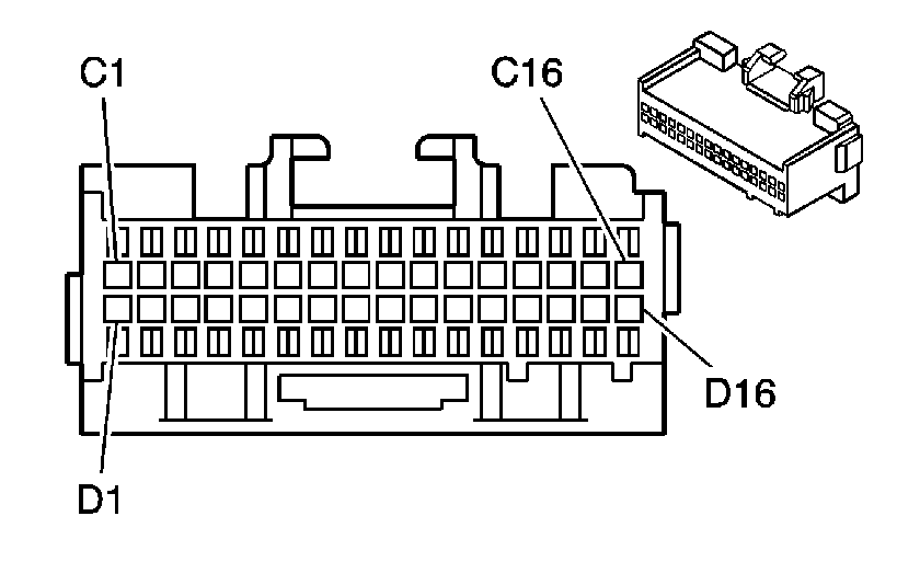
C1 | LT BLU/BLK | 590 | Sunload Sensor Signal | ||||
C2 | BRN | 404 | Upper Air Temperature Sensor Signal | ||||
C3 | LT GRN | 405 | Lower Air Temperature Sensor Signal | ||||
C4 | LT BLU | 733 | Air Temperature Door Position Signal | ||||
C5 | PPL | 1838 | Recirculation Door Position Signal | ||||
C6 | BRN | 341 | Ignition 3 Voltage | ||||
C7 | DK GRN | 1614 | Recirculation Door Control | ||||
C8 | WHT | 119 | Mode Door Control | ||||
C9 | DK BLU | 1199 | Air Temperature Door Control | ||||
C10 | BLK | 2450 | Ground | ||||
C11 | WHT | 1038 | HVAC Class 2 Serial Data | ||||
C12 | ORN | 340 | Battery Positive Voltage | ||||
C13-C15 | -- | -- | Not Used | ||||
C16 | GRY/BLK | 754 | Blower Motor Speed Control | ||||
D1 | DK GRN | 734 | Inside Air Temperature Sensor Signal | ||||
D2 | LT GRN/BLK | 735 | Ambient Air Temperature Sensor Signal | ||||
D3 | RED | 708 | Mode Door Position Signal | ||||
D4 | -- | -- | Not Used | ||||
D5 | GRY | 598 | 5 Volt Reference | ||||
D6 | -- | -- | Not Used | ||||
D7 | GRY | 8 | Instrument Panel Lamp Supply Voltage - 1 | ||||
D8 | LT BLU | 203 | A/C Request Signal | ||||
D9 | BRN | 718 | Low Reference | ||||
D10 | GRY/BLK | 1798 | Ground | ||||
D11 | LT BLU | 2820 | HVAC Control Module Clock Signal | ||||
D12 | RED | 2819 | HVAC Control Module Data Signal | ||||
D13 | -- | -- | Not Used | ||||
D14 | WHT | 193 | Rear Defog Relay Control | ||||
D15-D16 | -- | -- | Not Used | ||||
| |||||||
|---|---|---|---|---|---|---|---|
Connector Part Information |
| ||||||
Pin | Wire Color | Circuit No. | Function | ||||
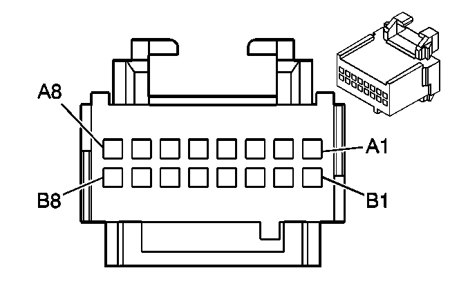
A1 | GRY | 8 | Instrument Panel Lamp Supply Voltage - 1 | ||||
A2-A4 | -- | -- | Not Used | ||||
A5 | WHT | 1924 | Auxiliary Blower Motor High Speed Control | ||||
A6 | RED | 1925 | Auxiliary Blower Motor Medium Speed Control | ||||
A7 | DK BLU | 1926 | Auxiliary Blower Motor Low Speed Control | ||||
A8 | BLK | 1450 | Ground | ||||
B1-B3 | -- | -- | Not Used | ||||
B4 | BLK | 1450 | Ground -Loop Anchor | ||||
B5-B7 | -- | -- | Not Used | ||||
B8 | BLK | 1450 | Ground -Loop Anchor | ||||

| |||||||
|---|---|---|---|---|---|---|---|
Connector Part Information |
| ||||||
Pin | Wire Color | Circuit No. | Function | ||||
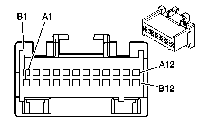
A1 | -- | -- | Not Used | ||||
A2 | GRY | 2821 | 5 Volt Reference | ||||
A3-A4 | -- | -- | Not Used | ||||
A5 | BLK | 1050 | Ground | ||||
A6-A7 | -- | -- | Not Used | ||||
A8 | GRY | 8 | Instrument Panel Lamp Supply Voltage - 1 | ||||
B1 | BLK | 2930 | Temperature Switch Control | ||||
B2 | -- | -- | Not Used | ||||
B3 | WHT | 454 | Mode Door Control - Auxiliary | ||||
B4-B5 | -- | -- | Not Used | ||||
B6 | BLK/WHT | 2933 | Low Reference | ||||
B7 | -- | -- | Not Used | ||||
B8 | PPL/WHT | 760 | Auxiliary Blower Motor Speed Control | ||||
| |||||||
|---|---|---|---|---|---|---|---|
Connector Part Information |
| ||||||
Pin | Wire Color | Circuit No. | Function | ||||
A1 | -- | -- | Not Used | ||||
A2 | PPL | 374 | Auxiliary Blower Motor Speed Control | ||||
A3 | WHT/BLK | 1236 | Air Temperature Door Control - Auxiliary | ||||
A4 | WHT | 454 | Mode Door Control - Auxiliary | ||||
A5 | -- | -- | Not Used | ||||
A6 | TAN | 517 | Air Temperature Sensor Signal - Upper Auxiliary | ||||
A7 | BLK | 520 | Lower Auxiliary Air Temperature Sensor Signal | ||||
A8 | BLK | 1450 | Ground | ||||
A9 | BLK | 1050 | Ground | ||||
A10 | BLK | 808 | Low Reference | ||||
A11 | BLK | 2930 | Temperature Switch Control | ||||
A12 | PPL/WHT | 760 | Auxiliary Blower Motor Speed Control | ||||
B1 | BRN | 541 | Ignition 3 Voltage | ||||
B2 | GRY | 8 | Instrument Panel Lamp Supply Voltage - 1 | ||||
B3 | GRY | 8 | Instrument Panel Lamp Supply Voltage - 1 | ||||
B4 | DK BLU | 1646 | Air Temperature Door Position Signal - Auxiliary | ||||
B5 | YEL/BLK | 1814 | Lower Mode Door Position Signal | ||||
B6 | GRY | 598 | 5 Volt Reference | ||||
B7 | GRY | 2821 | 5 Volt Reference | ||||
B8 | LT BLU | 2820 | HVAC Control Module Clock Signal | ||||
B9 | RED | 2819 | HVAC Control Module Data Signal | ||||
B10 | GRY/BLK | 1798 | Ground | ||||
B11 | BLK/WHT | 2933 | Low Reference | ||||
B12 | WHT | 454 | Mode Door Control - Auxiliary | ||||
| |||||||
|---|---|---|---|---|---|---|---|
Connector Part Information |
| ||||||
Pin | Wire Color | Circuit No. | Function | ||||
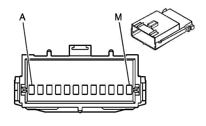
A | LT BLU | 733 | Air Temperature Door Position Signal | ||||
B | WHT/BLK | 1236 | Air Temperature Door Control - Auxiliary | ||||
C | DK BLU | 1646 | Air Temperature Door Position Signal - Auxiliary | ||||
D | LT BLU | 2823 | Mode Signal - Auxiliary Rear | ||||
E | LT BLU | 2822 | Mode Signal - Auxiliary Front | ||||
F | WHT | 454 | Mode Door Control - Auxiliary | ||||
G | -- | -- | Not Used | ||||
H | BLK | 1450 | Ground | ||||
J | BRN | 541 | Ignition 3 Voltage | ||||
K | -- | -- | Not Used | ||||
L | GRY | 778 | Blower Motor Control - Auxiliary | ||||
M | ORN | 1923 | Rear Auxiliary Enable Control | ||||

| |||||||
|---|---|---|---|---|---|---|---|
Connector Part Information |
| ||||||
Pin | Wire Color | Circuit No. | Function | ||||
5 | BRN | 341 | Ignition 3 Voltage | ||||
6 | WHT | 119 | Mode Door Control | ||||
7 | GRY/BLK | 1798 | Ground | ||||
8 | -- | -- | Not Used | ||||
9 | RED | 708 | Mode Door Position Signal | ||||
10 | GRY | 598 | 5 Volt Reference | ||||

| |||||||
|---|---|---|---|---|---|---|---|
Connector Part Information |
| ||||||
Pin | Wire Color | Circuit No. | Function | ||||
5 | BRN | 541 | Ignition 3 Voltage | ||||
6 | WHT | 454 | Mode Door Control - Auxiliary | ||||
7 | GRY/BLK | 1798 | Ground | ||||
8 | -- | -- | Not Used | ||||
9 | YEL/BLK | 1814 | Lower Mode Door Position Signal | ||||
10 | GRY | 598 | 5 Volt Reference | ||||

| |||||||
|---|---|---|---|---|---|---|---|
Connector Part Information |
| ||||||
Pin | Wire Color | Circuit No. | Function | ||||
5-6 | -- | -- | Not Used | ||||
7 | BLK | 1450 | Ground | ||||
8 | WHT/BLK | 1236 | Auxiliary Air Temperature Control | ||||
9 | -- | -- | Not Used | ||||
10 | BRN | 541 | Ignition 3 Voltage | ||||

| |||||||
|---|---|---|---|---|---|---|---|
Connector Part Information |
| ||||||
Pin | Wire Color | Circuit No. | Function | ||||
5 | BRN | 341 | Ignition 3 Voltage | ||||
6 | DK GRN | 1614 | Recirculation Door Control | ||||
7 | GRY/BLK | 1798 | Ground | ||||
8 | -- | -- | Not Used | ||||
9 | PPL | 1838 | Recirculation Door Position Signal | ||||
10 | GRY | 598 | 5 Volt Reference | ||||

| |||||||
|---|---|---|---|---|---|---|---|
Connector Part Information |
| ||||||
Pin | Wire Color | Circuit No. | Function | ||||
A | LT BLU/BLK | 590 | Sunload Sensor Signal | ||||
B | BRN | 718 | Low Reference | ||||
