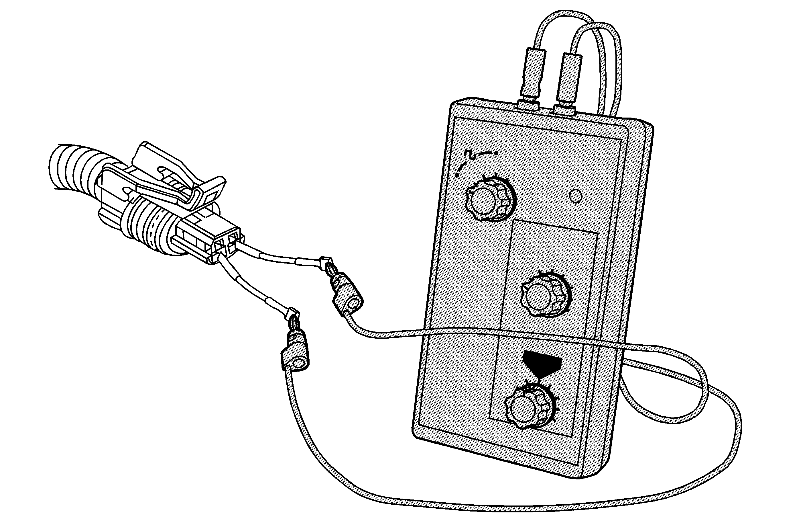
Special Tools
J 38522
Variable Signal Generator

The purpose of this test is to provide a simulated output speed sensor (OSS) signal to the control solenoid (w/body and TCM) valve assembly OSS input circuits.
- Disconnect the OSS wiring harness connector from the OSS assembly.
- Using a terminal test kit, connect the red lead of
J 38522
to the OSS signal circuit terminal B and the black lead to the OSS supply voltage circuit terminal A.
| 2.1. | Set the
J 38522
Signal to 8 volts, the Frequency to 120 and the Percent Duty Cycle to 50. |
| 2.2. | With the ignition ON, observe the scan tool parameter OSS Signal. |
| 2.3. | The signal parameter should display between 100-400 RPM. |
| ⇒ | If the signal display is not in this range, test the OSS signal and supply voltage circuits for an open/high resistance, short to ground, or short to voltage. If the circuits test normal, the control solenoid (w/body and TCM) valve assembly is not
reading the input signal correctly and is faulty. |

