Fuse Block, Underhood -- Label
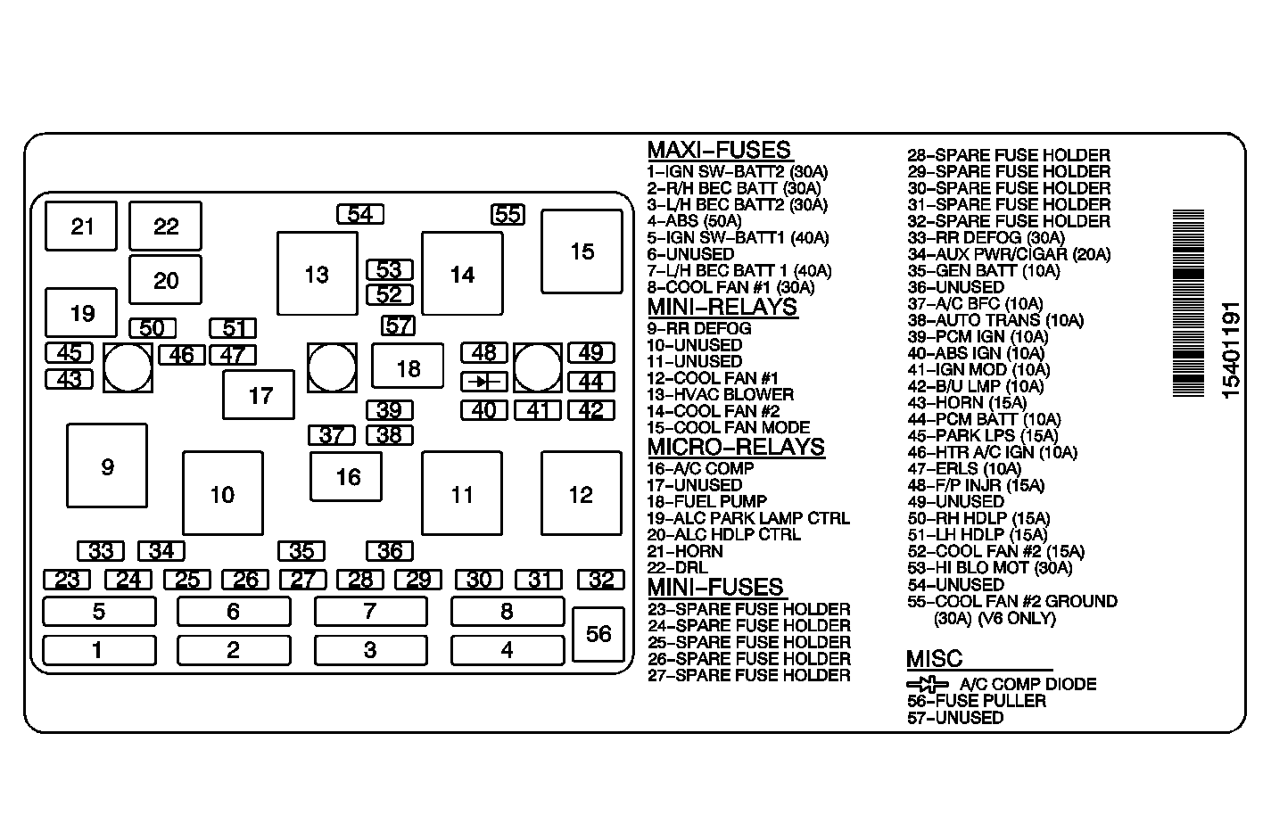
No. | Device | Rating | Description |
|---|---|---|---|
1 | IGN SW - BATT2 Fuse | 30A | Ignition Switch |
2 | R/H BEC BATT Fuse | 30A | RH I/P Junction Block |
3 | L/H BEC BATT2 Fuse | 30A | LH I/P Junction Block |
4 | ABS Fuse | 50A | Electronic Brake Control (ABS) Relay |
5 | IGN SW - BATT1 Fuse | 40A | Ignition Switch |
6 | -- | -- | Not Used |
7 | L/H BEC BATT1 Fuse | 40A | LH I/P Junction Block |
8 | COOL FAN #1 Fuse | 30A | Fan Control Relay #1 |
9 | RR Defog Mini Relay | -- | Rear Defogger |
10-11 | -- | -- | Not Used |
12 | Cool fan #1 Relay | -- | Cooling Fan - Left |
13 | HVAC Blower Relay | -- | Blower Motor |
14 | Cool Fan #2 Relay | -- | Cooling Fan - Right |
15 | Cool Fan Mode Relay | -- | Switches from Only the Left Cooling Fan to Both Cooling Fans |
16 | A/C Comp Relay | -- | A/C Compressor Clutch |
17 | -- | -- | Not Used |
18 | Fuel Pump Relay | -- | Controlled from the PCM, Controls the Fuel pump |
19 | ALC Park Lamp Control Relay | -- | Marker Lamps |
20 | ALC Headlamp Control Relay | -- | Marker Lamps with Headlamps On |
21 | Horn Relay | -- | Horn |
22 | DRL Relay | -- | Daytime Running Lamps |
23 - 32 | -- | -- | Spare |
33 | RR DEFOG | 30A | Rear Defogger |
34 | AUX PWR/CIGAR | 20A | Auxiliary Power Outlet and Cigar Lighter (Chevrolet) |
35 | GEN BATT | 10A | Generator |
36 | -- | -- | Not Used |
37 | A/C BFC | 10A | A/C Compressor Clutch and Body Control Module (BCM) |
38 | AUTO TRANS | 10A | Automatic Transaxle |
39 | PCM IGN | 10A | Powertrain Control Module (PCM) |
40 | ABS IGN | 10A | Electronic Brake Control Module (EBCM) |
41 | IGN MOD | 10A | Ignition Control (IC) Module |
42 | B/U LMP | 10A | Park/Neutral Position Switch |
43 | HORN | 15A | Horn |
44 | PCM BATT | 10A | Powertrain Control Module (PCM) |
45 | PARK LPS | 15A | Park Lamps |
46 | HTR A/C IGN | 10A | Daytime Running Lamps (DRL), Rear Defogger, Heater A/C Control Assembly, and Air Temperature Actuator |
47 | ERLS | 10A | EVAP, EGR, PCM, HO2S 1, and HO2S 2 |
48 | F/P INJR | 15A | Fuel Pump and Fuel Injectors |
49 | -- | -- | Not Used |
50 | RH HDLP | 15A | Headlamps Right Side |
51 | LH HDLP | 15A | Headlamps, Left Side |
52 | COOL FAN #2 | 15A | Fan Control Relay #2 |
53 | HI BLO MOT | 30A | Blower Motor |
54 | -- | -- | Not Used |
55 | COOL FAN #2 Ground (V-6 ONLY) | 30A | Cooling Fans (V-6 Only) |
Misc | A/C Comp Diode | -- | A/C Compressor |
| Figure 1: |
Fuse Block Underhood - Top View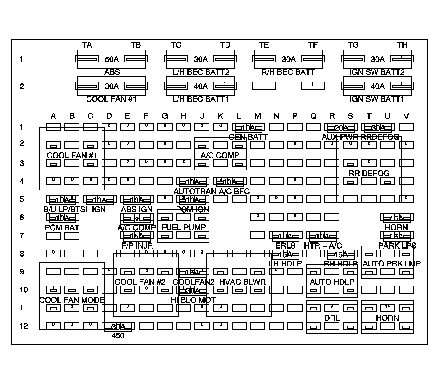
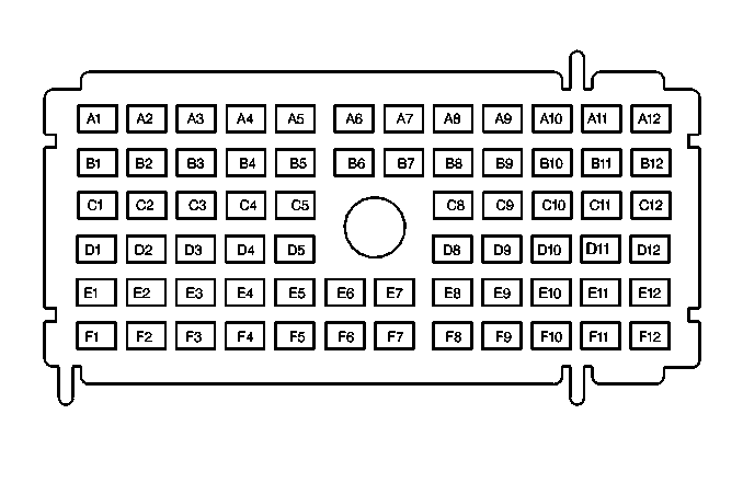
| ||||||
| Figure 2: |
Fuse Block - Underhood - Bottom View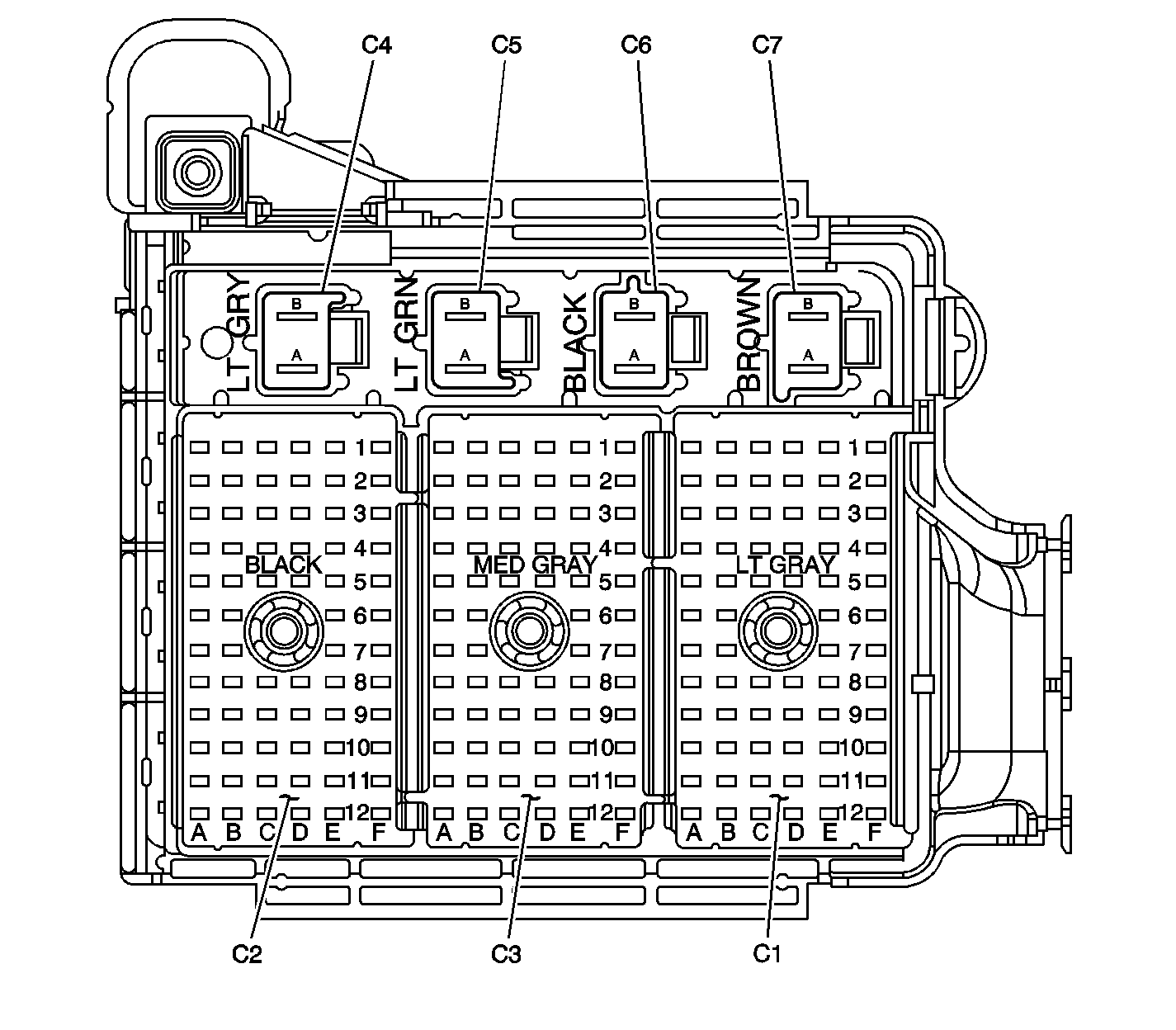
| ||||||
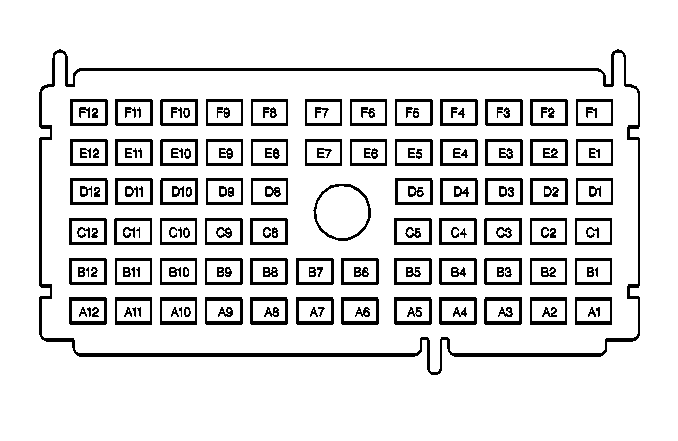
| |||||||
|---|---|---|---|---|---|---|---|
Connector Part Information |
| ||||||
Pin | Wire Color | Circuit No. | Function | ||||
A1 | -- | -- | Not Used | ||||
A2 | DK GRN/WHT | 459 | A/C Clutch Relay Control | ||||
A3 | -- | -- | Not Used | ||||
A4 | PNK | 1039 | Ignition 1 Voltage | ||||
PNK | 1039 | Ignition 1 Voltage | |||||
A5 | -- | -- | Not Used | ||||
A6 | GRY | 729 | A/C Compressor Clutch Solenoid Control | ||||
A7 | PNK | 839 | Ignition 1 Voltage | ||||
A8-A10 | -- | -- | Not Used | ||||
A11 | YEL | 5 | Crank Voltage | ||||
A12 | LT BLU | 20 | Stop Lamp Supply Voltage (JM4) | ||||
B1-B4 | -- | -- | Not Used | ||||
B5 | PNK | 139 | Ignition 1 Voltage (JM4) | ||||
B6 | DK GRN | 59 | A/C Compressor Clutch Supply Voltage | ||||
B7 | -- | -- | Not Used | ||||
B8 | BLK | 450 | Ground | ||||
B9-B12 | -- | -- | Not Used | ||||
C1-C2 | -- | -- | Not Used | ||||
C3 | DK GRN | 83 | Cruise Control Inhibit Signal | ||||
C4-C5 | -- | -- | Not Used | ||||
C8 | PNK | 639 | Ignition 1 Voltage | ||||
C9 | -- | -- | Not Used | ||||
C10 | GRY | 532 | Coolant Fan Motor Supply Voltage | ||||
C11 | LT BLU/BLK | 396 | Cruise Control Engaged Signal | ||||
C12 | -- | -- | Not Used | ||||
D1-D2 | -- | -- | Not Used | ||||
D3 | DK GRN | 335 | Low Speed Cooling Fan Relay Control | ||||
D4 | -- | -- | Not Used | ||||
D5 | PNK | 239 | Ignition 1 Voltage | ||||
D8-D9 | -- | -- | Not Used | ||||
D10 | BLK | 450 | Ground | ||||
D11 | DK BLU | 473 | High Speed Cooling Fan Relay Control | ||||
D12 | -- | -- | Not Used | ||||
E1-E2 | -- | -- | Not Used | ||||
E3 | PPL | 420 | TCC Brake Switch Signal | ||||
E4-E5 | -- | -- | Not Used | ||||
E6 | ORN | 480 | Powertrain Control Module Positive Voltage | ||||
E7 | -- | -- | Not Used | ||||
E8 | DK GRN/WHT | 465 | Fuel Pump Relay Control - Primary | ||||
E9 | BRN | 241 | Ignition 3 Voltage | ||||
E10-E12 | -- | -- | Not Used | ||||
F1-F2 | -- | -- | Not Used | ||||
F3 | LT BLU | 409 | Cooling Fan Motor Supply Voltage | ||||
F4 | -- | -- | Not Used | ||||
F5 | PNK | 539 | Ignition 1 Voltage | ||||
F6-F8 | -- | -- | Not Used | ||||
F9 | BRN | 241 | Ignition 3 Voltage | ||||
F10 | -- | -- | Not Used | ||||
F11 | WHT | 504 | Cooling Fan Motor Ground | ||||
F12 | -- | -- | Not Used | ||||
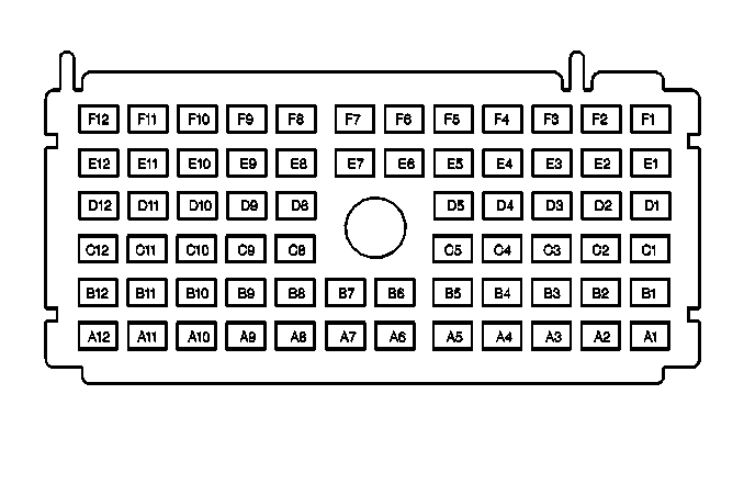
| |||||||
|---|---|---|---|---|---|---|---|
Connector Part Information |
| ||||||
Pin | Wire Color | Circuit No. | Function | ||||
A1 | BRN | 341 | Ignition 3 Voltage | ||||
A2-A3 | -- | -- | Not Used | ||||
A4 | ORN | 740 | Battery Positive Voltage | ||||
A5-A9 | -- | -- | Not Used | ||||
A10 | DK BLU | 15 | Right Front Turn Signal Lamp Positive Voltage | ||||
A11-A12 | -- | -- | Not Used | ||||
B1-B4 | -- | -- | Not Used | ||||
B5 | BRN | 9 | Park Lamp Supply Voltage | ||||
B6-B9 | -- | -- | Not Used | ||||
B10 | DK BLU | 15 | Right Front Turn Signal Lamp Positive Voltage | ||||
B11 | LT BLU | 14 | Left Front Turn Signal Lamp Positive Voltage | ||||
B12 | LT BLU | 20 | Stop Lamp Supply Voltage | ||||
C1-C3 | -- | -- | Not Used | ||||
C4 | ORN | 740 | Battery Positive Voltage | ||||
C5 | BRN | 9 | Park Lamp Supply Voltage | ||||
C8-C9 | -- | -- | Not Used | ||||
C10 | LT BLU | 14 | Left Front Turn Signal Lamp Positive Voltage | ||||
C11 | -- | -- | Not Used | ||||
C12 | DK GRN | 29 | Horn Control | ||||
D1-D4 | -- | -- | Not Used | ||||
D5 | BRN | 9 | Park Lamp Supply Voltage | ||||
D8-D10 | -- | -- | Not Used | ||||
D11 | GRY | 589 | DRL Resistor Supply Voltage | ||||
D12 | -- | -- | Not Used | ||||
E1-E3 | -- | -- | Not Used | ||||
E4 | DK GRN | 83 | Cruise Control Inhibit Signal | ||||
E5 | BRN | 9 | Park Lamp Supply Voltage | ||||
E6 | PNK | 1200 | Headlamp Output (High Beam) | ||||
E7 | -- | -- | Not Used | ||||
E8 | ORN | 640 | Battery Positive Voltage | ||||
E9 | LT BLU/BLK | 396 | Cruise Control Engaged Signal | ||||
E10-E11 | -- | -- | Not Used | ||||
E12 | DK BLU | 1201 | Headlamp Output (Low Beam) | ||||
F1-F3 | -- | -- | Not Used | ||||
F4 | PPL | 420 | TCC Brake Switch Signal | ||||
F5 | -- | -- | Not Used | ||||
F6 | PNK | 1200 | Headlamp Output (High Beam) | ||||
F7 | -- | -- | Not Used | ||||
F8 | ORN | 640 | Battery Positive Voltage | ||||
F9-F11 | -- | -- | Not Used | ||||
F12 | DK BLU | 1201 | Headlamp Output (Low Beam) | ||||
| |||||||
|---|---|---|---|---|---|---|---|
Connector Part Information |
| ||||||
Pin | Wire Color | Circuit No. | Function | ||||
A1 | ORN | 40 | Battery Positive Voltage | ||||
ORN | 40 | Battery Positive Voltage | |||||
A2-A3 | -- | -- | Not Used | ||||
A4 | PPL | 420 | TCC Brake Switch Signal | ||||
A5 | -- | -- | Not Used | ||||
A6 | ORN | 300 | Ignition 3 Voltage | ||||
A7 | BRN | 241 | Ignition 3 Voltage | ||||
A8-A9 | -- | -- | Not Used | ||||
A10 | BLK | 150 | Ground | ||||
A11 | BRN | 41 | Ignition 3 Voltage | ||||
BRN | 41 | Ignition 3 Voltage | |||||
A12 | DK BLU | 1201 | Headlamp Output (Low Beam) | ||||
B1 | -- | -- | Not Used | ||||
B2 | WHT | 193 | Rear Defogger Relay Control | ||||
B3 | DK GRN | 306 | Headlamp Switch Headlamps Off Signal | ||||
B4-B6 | -- | -- | Not Used | ||||
B7 | PNK | 1200 | Headlamp Output (High Beam) | ||||
B8 | WHT | 1080 | Park Lamp Relay Control | ||||
B9 | PPL | 65 | Blower Motor Supply Voltage | ||||
B10-B11 | -- | -- | Not Used | ||||
B12 | LT GRN/BLK | 592 | DRL Relay Control | ||||
C1-C3 | -- | -- | Not Used | ||||
C4 | PNK | 439 | Ignition 1 Voltage | ||||
C5 | PPL | 293 | Rear Defogger Element Supply Voltage | ||||
C8 | DK BLU | 15 | Right Front Turn Signal Lamp Positive Voltage | ||||
C9 | LT BLU | 14 | Left Front Turn Signal Lamp Positive Voltage | ||||
C10 | DK BLU | 101 | Blower Motor Supply Voltage | ||||
C11 | PNK/WHT | 1970 | Headlamps Low Beam Relay Control | ||||
C12 | BLK | 28 | Horn Relay Control | ||||
BLK | 28 | Horn Relay Control | |||||
D1 | -- | -- | Not Used | ||||
D2 | BRN | 341 | Ignition 3 Voltage | ||||
D3-D4 | -- | -- | Not Used | ||||
D5 | PNK | 3 | Ignition 1 Voltage | ||||
D8 | ORN | 240 | Battery Positive Voltage | ||||
D9 | ORN | 52 | High Blower Motor Control | ||||
D10-D12 | -- | -- | Not Used | ||||
E1-E5 | -- | -- | Not Used | ||||
E6 | GRY | 120 | Fuel Pump Supply Voltage | ||||
E7-E12 | -- | -- | Not Used | ||||
F1 | RED | 842 | Battery Positive Voltage | ||||
F2-F6 | -- | -- | Not Used | ||||
F7 | BRN | 9 | Park Lamp Supply Voltage | ||||
F8-F10 | -- | -- | Not Used | ||||
F11 | YEL | 5 | Crank Voltage | ||||
F12 | LT BLU | 20 | Stop Lamp Supply Voltage | ||||
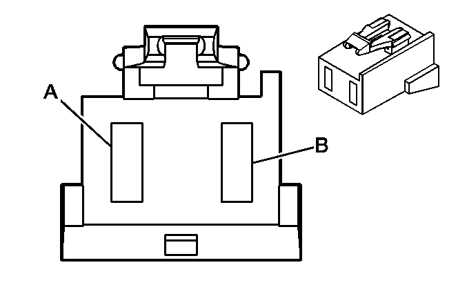
| |||||||
|---|---|---|---|---|---|---|---|
Connector Part Information |
| ||||||
Pin | Wire Color | Circuit No. | Function | ||||
A | RED | 442 | Battery Positive Voltage | ||||
B | RED/BLK | 242 | Battery Positive Voltage | ||||
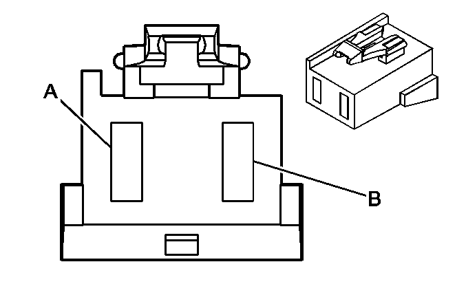
| |||||||
|---|---|---|---|---|---|---|---|
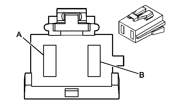
Connector Part Information |
| ||||||
Pin | Wire Color | Circuit No. | Function | ||||
A | -- | -- | Not Used | ||||
B | RED | 1042 | Battery Positive Voltage | ||||
| |||||||
|---|---|---|---|---|---|---|---|
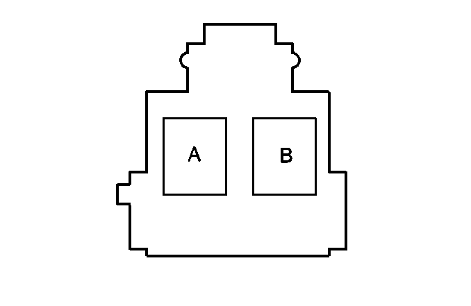
Connector Part Information |
| ||||||
Pin | Wire Color | Circuit No. | Function | ||||
A | RED | 642 | Battery Positive Voltage | ||||
B | RED | 642 | Battery Positive Voltage | ||||
| |||||||
|---|---|---|---|---|---|---|---|
Connector Part Information |
| ||||||
Pin | Wire Color | Circuit No. | Function | ||||
A | -- | -- | Not Used | ||||
B | RED | 342 | Battery Positive Voltage | ||||
Fuse Block, Left I/P -- Label
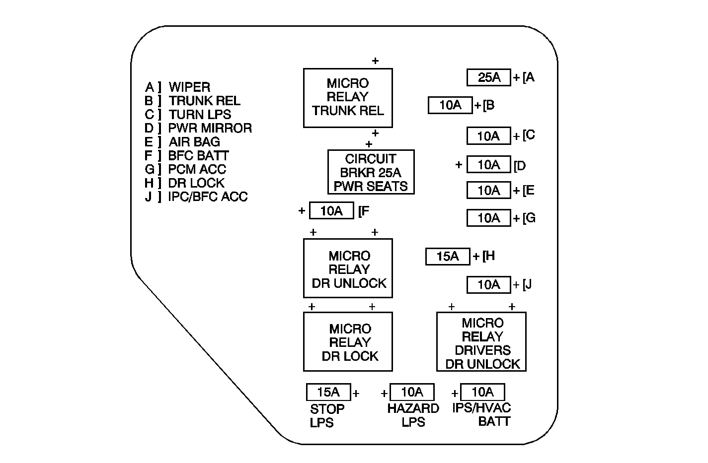
No. | Device | Rating | Description |
|---|---|---|---|
A | WIPER Fuse | 25A | Wiper Motor |
B | TRUNK REL/RFA Fuse | 10A | Rear Compartment Lid Release and Remote Control Door Lock Receiver (RFA) |
C | Turn LPS Fuse | 10A | Hazard Switch and Turn Signal Lamps |
D | PWR MIRROR Fuse | 10A | Power Mirrors |
E | AIR BAG Fuse | 10A | Sensing Diagnostic Module (SDM) |
F | BFC BATT Fuse | 10A | Body Control Module (BCM) |
G | PCM ACC Fuse | 10A | Powertrain Control Module (PCM) |
H | Door Lock Fuse | 10A | Radio |
J | IPC/BFC ACC Fuse | 10A | Instrument Cluster and Body Control Module (BCM) |
-- | STOP LPS Fuse | 15A | Stop Lamps |
-- | IPS/HVAC Fuse | 10A | Turn Lamps |
-- | HAZARD LPS Fuse | 10A | Hazard Lamps |
-- | Trunk Release Relay | -- | Rear Compartment Lid Release |
-- | DR Unlock Relay | -- | All Doors Unlock |
-- | DR Lock Relay | -- | All Doors Lock |
-- | Drivers Door Unlock Relay | -- | Drivers Door Unlock |
-- | PWR Seats Circuit Breaker | 25A | Power Seats |
| Figure 3: |
Fuse Block, Left I/P -- Top View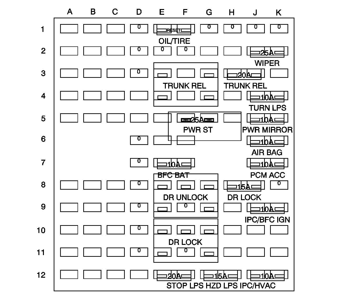
| ||||||
| Figure 4: |
Fuse Block, Left I/P, C1, C2 -- Bottom View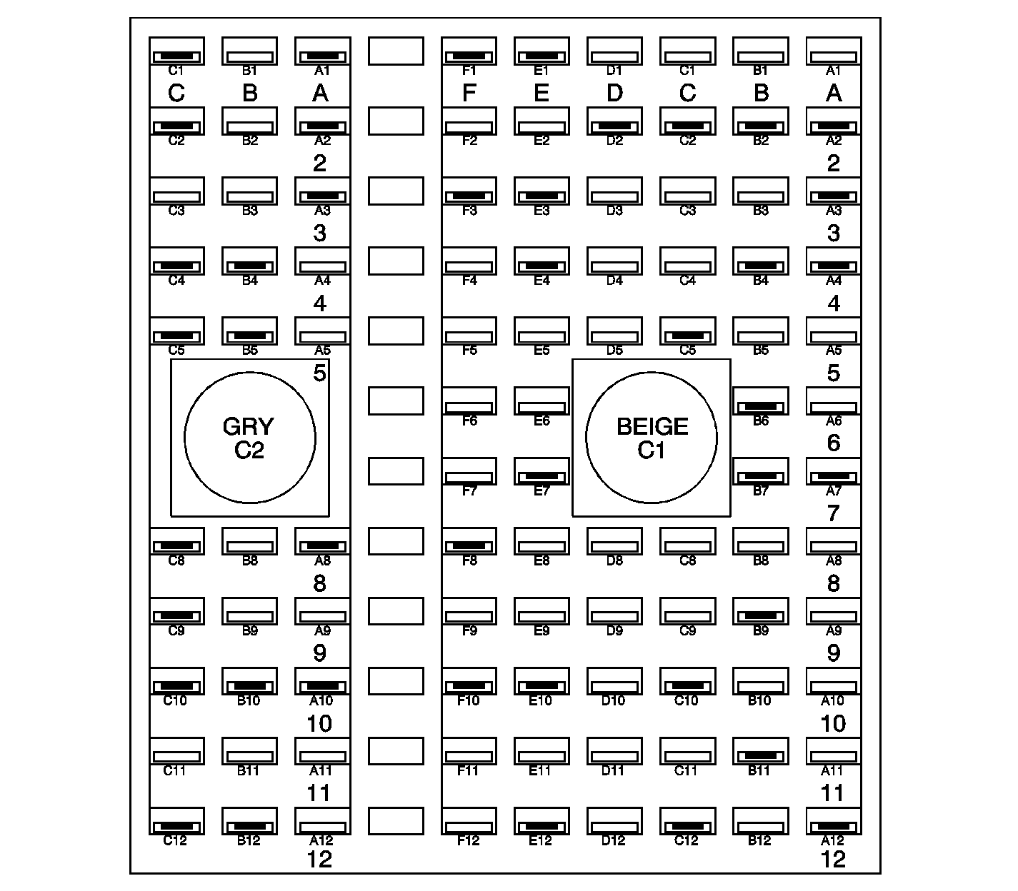
| ||||||
| Figure 5: |
Fuse Block, Left I/P, C3 -- Bottom View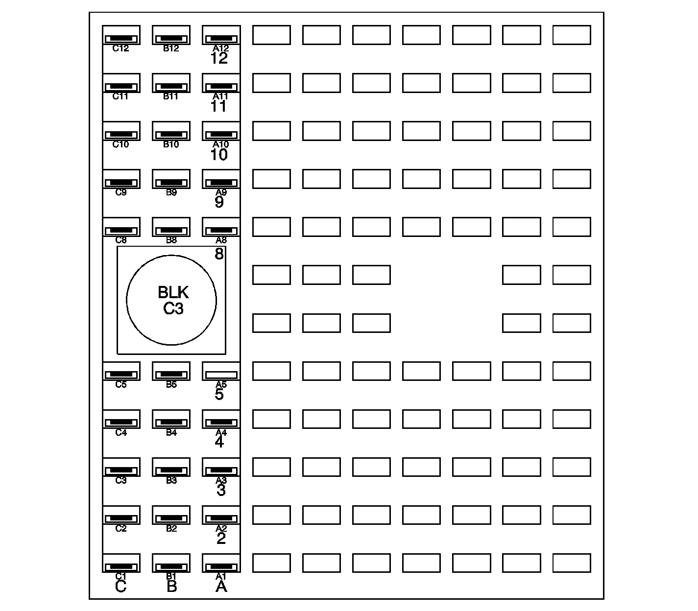
| ||||||
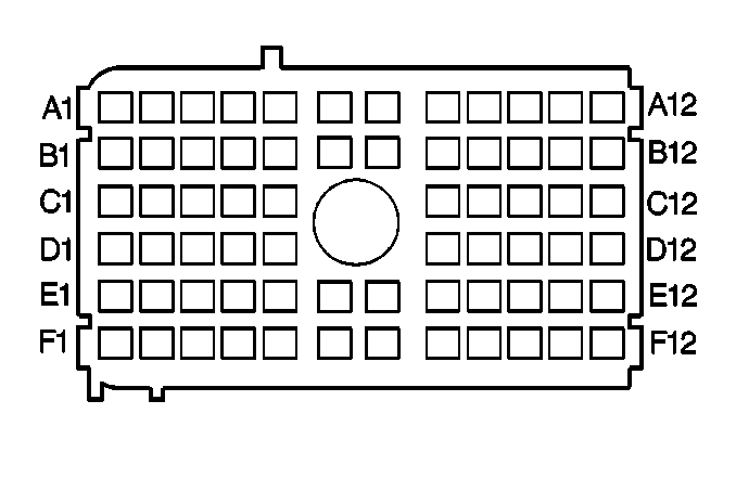
| |||||||
|---|---|---|---|---|---|---|---|
Connector Part Information |
| ||||||
Pin | Wire Color | Circuit No. | Function | ||||
A1 | -- | -- | Not Used | ||||
A2 | BRN | 4 | Accessory Voltage | ||||
A3 | PPL | 1807 | Class 2 Serial Data (Primary) | ||||
A4 | PNK | 3 | Ignition 1 Voltage | ||||
A5-A6 | -- | -- | Not Used | ||||
A7 | DK GRN | 500 | Ignition 0 Voltage | ||||
A8-A11 | -- | -- | Not Used | ||||
A12 | ORN | 1440 | Battery Positive Voltage | ||||
ORN | 1440 | Battery Positive Voltage | |||||
B1 | -- | -- | Not Used | ||||
B2 | YEL | 143 | Accessory Voltage | ||||
B3 | -- | -- | Not Used | ||||
B4 | PNK | 739 | Ignition 1 Voltage | ||||
B5 | -- | -- | Not Used | ||||
B6 | YEL | 1139 | Ignition 1 Voltage | ||||
B7 | PPL | 1500 | Ignition 0 Voltage | ||||
B8-B10 | -- | -- | Not Used | ||||
B11 | ORN | 1440 | Battery Positive Voltage | ||||
B12 | -- | -- | Not Used | ||||
C1 | -- | -- | Not Used | ||||
C2 | YEL | 143 | Accessory Voltage | ||||
C3 | -- | -- | Not Used | ||||
C4 | DK GRN/WHT | 817 | VSS Signal | ||||
C5 | RED | 442 | Battery Positive Voltage | ||||
C8 | -- | -- | Not Used | ||||
C9 | PPL | 1600 | Ignition 0 Voltage | ||||
PPL | 1600 | Ignition 0 Voltage | |||||
C10 | YEL | 356 | Driver Door Lock Relay Unlock | ||||
C11 | -- | -- | Not Used | ||||
C12 | ORN | 1140 | Battery Positive Voltage | ||||
D1 | -- | -- | Not Used | ||||
D2 | PPL | 1807 | Class 2 Serial Data (Primary) | ||||
PPL | 1807 | Class 2 Serial Data (Primary) | |||||
D3-D5 | -- | -- | Not Used | ||||
D8-D12 | -- | -- | Not Used | ||||
E1-E2 | -- | -- | Not Used | ||||
E3 | PPL | 1807 | Class 2 Serial Data (Primary) | ||||
PPL | 1807 | Class 2 Serial Data (Primary) | |||||
E4 | WHT | 156 | Courtesy Lamp Low Control | ||||
E5 | -- | -- | Not Used | ||||
E6 | DK GRN/WHT | 817 | VSS Signal | ||||
E7 | ORN | 1540 | Battery Positive Voltage | ||||
E8 | -- | -- | Not Used | ||||
E9 | ORN | 1732 | Courtesy Lamps Supply Voltage | ||||
E10 | BLK | 150 | Ground | ||||
E11 | -- | -- | Not Used | ||||
E12 | RED | 642 | Battery Positive Voltage | ||||
F1-F2 | -- | -- | Not Used | ||||
F3 | LT BLU | 1344 | Trunk Release Relay Control | ||||
F4-F5 | -- | -- | Not Used | ||||
F6 | DK GRN/WHT | 817 | VSS Signal | ||||
F7 | -- | -- | Not Used | ||||
F8 | WHT | 194 | Door Unlock Control | ||||
F9 | -- | -- | Not Used | ||||
F10 | LT BLU | 195 | Door Lock Control | ||||
F11-F12 | -- | -- | Not Used | ||||
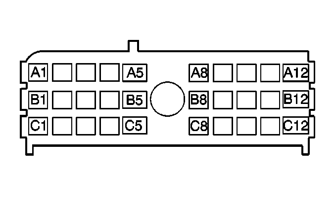
| |||||||
|---|---|---|---|---|---|---|---|
Connector Part Information |
| ||||||
Pin | Wire Color | Circuit No. | Function | ||||
A1-A12 | -- | -- | Not Used | ||||
B1 - B5 | -- | -- | Not Used | ||||
B8-B11 | -- | -- | Not Used | ||||
B12 | PPL | 420 | TCC Brake Switch Signal | ||||
C1 | PPL | 293 | Rear Defogger Element Supply Voltage | ||||
C2 | BRN | 241 | Ignition 3 Voltage | ||||
C3 | -- | -- | Not Used | ||||
C4 | DK GRN/WHT | 1135 | A/T Shift Lock Solenoid Supply Voltage | ||||
C5 | GRY | 118 | Left Front Speaker Output (-) | ||||
C8 | -- | -- | Not Used | ||||
C9 | ORN | 1732 | Courtesy Lamp Supply Voltage | ||||
C10-C11 | -- | -- | Not Used | ||||
C12 | LT BLU | 1134 | Park Brake Switch Signal | ||||
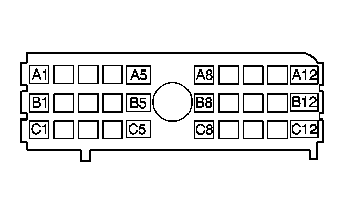
| |||||||
|---|---|---|---|---|---|---|---|
Connector Part Information |
| ||||||
Pin | Wire Color | Circuit No. | Function | ||||
A1 | ORN | 140 | Battery Positive Voltage | ||||
A2 | GRY | 295 | Door Lock Motor Lock | ||||
GRY | 295 | Door Lock Motor Lock | |||||
A3 | -- | -- | Not Used | ||||
A4 | TAN | 294 | Door Lock Motor Unlock | ||||
A5 | -- | -- | Not Used | ||||
A8 | ORN | 540 | Battery Positive Voltage | ||||
A9 | BLK/WHT | 56 | Trunk Release Motor (Control or Supply Voltage) | ||||
A10 | -- | -- | Not Used | ||||
A11 | ORN | 1040 | Battery Positive Voltage | ||||
A12 | -- | -- | Not Used | ||||
B1 | PPL | 420 | TCC Brake Switch Signal | ||||
B2 | GRY | 295 | Door Lock Motor Lock | ||||
GRY | 295 | Door Lock Motor Lock | |||||
B3 | -- | -- | Not Used | ||||
B4 | TAN | 294 | Door Lock Motor Unlock | ||||
TAN | 294 | Door Lock Motor Unlock | |||||
B5 | -- | -- | Not Used | ||||
B8 | TAN | 201 | Left Front Speaker Output (+) | ||||
B9 | LT GRN/BLK | 394 | Driver Door Ajar Switch Signal | ||||
B10 | ORN | 1840 | Battery Positive Voltage | ||||
B11 | -- | -- | Not Used | ||||
B12 | GRY | 120 | Fuel Pump Supply Voltage | ||||
C1 | LT BLU | 1134 | Park Brake Switch Signal | ||||
C2 | TAN | 694 | Not Used | ||||
C3 | ORN | 1732 | Courtesy Lamps Supply Voltage | ||||
C4 | ORN | 1732 | Courtesy Lamps Supply Voltage | ||||
ORN | 1732 | Courtesy Lamps Supply Voltage | |||||
C5 | -- | -- | Not Used | ||||
C8 | GRY | 118 | Left front Speaker Output (+) | ||||
C9 | DK GRN/WHT | 1135 | A/T Shift Lock Solenoid Supply Voltage | ||||
C10 | WHT | 156 | Courtesy Lamp Low Control | ||||
C11 | BRN | 241 | Ignition 3 Voltage | ||||
C12 | BLK | 293 | Rear Defogger Element Supply Voltage | ||||
Fuse Block, Right I/P -- Label
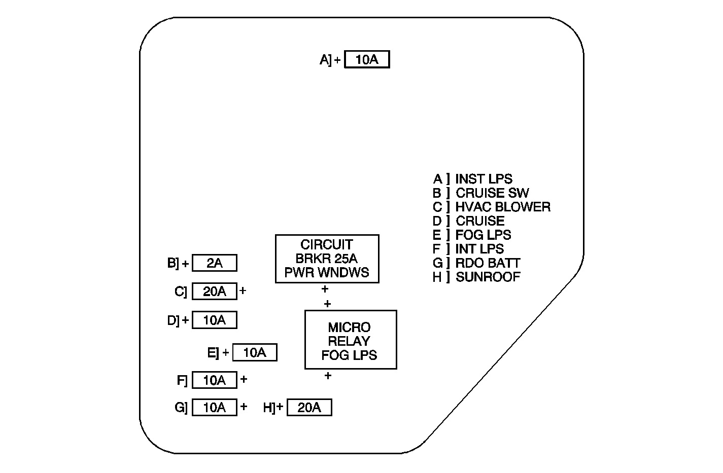
No. | Device | Rating | Description |
|---|---|---|---|
A | INT LPS | 10A | Interior Lamps (Non-Dimming) |
B | CRUISE SW | 2A | Cruise Control Switch |
C | HVAC BLOWER | 20A | Heater A/C Control Assembly |
D | CRUISE | 10A | Cruise Control Module |
E | FOG LPS | 10A | Fog Lamps |
F | INST LPS | 10A | Interior Lamps (Dimming) |
G | RDO BATT | 10A | Radio (Clock) |
H | SUNROOF | 20A | Sunroof Assembly |
-- | PWR WINDOWS Circuit Breaker | 25A | Power Windows |
-- | Fog LPS Relay | -- | Fog Lamps |
| Figure 6: |
Fuse Block Right I/P -- Top View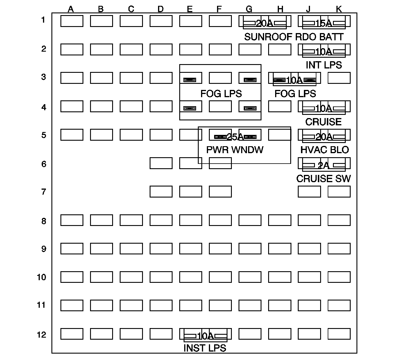
| ||||||
| Figure 7: |
Fuse Block, Right I/P, C1, C2 -- Bottom View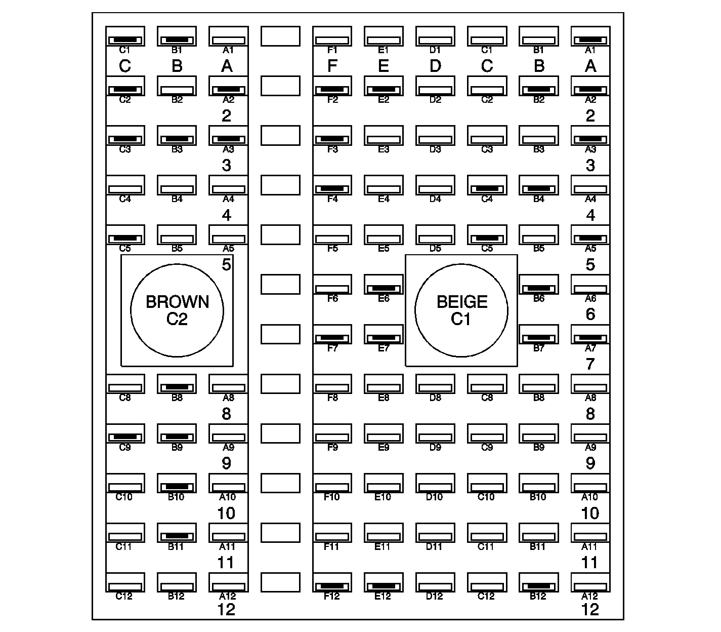
| ||||||
| Figure 8: |
Fuse Block, Right I/P, C3 -- Bottom View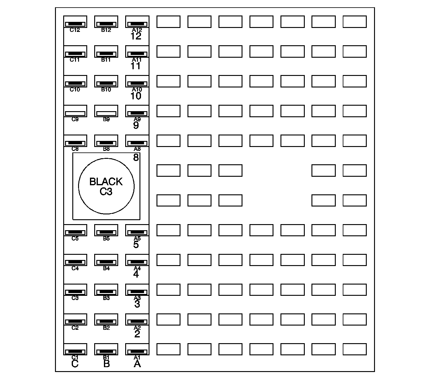
| ||||||

| |||||||
|---|---|---|---|---|---|---|---|
Connector Part Information |
| ||||||
Pin | Wire Color | Circuit No. | Function | ||||
A1 | ORN | 1740 | Battery Positive Voltage | ||||
A2 | ORN | 340 | Battery Positive Voltage | ||||
A3-A4 | -- | -- | Not Used | ||||
A5 | BRN | 641 | Ignition 3 Voltage | ||||
A6-A12 | -- | -- | Not Used | ||||
B1 | -- | -- | Not Used | ||||
B2 | RED | 1042 | Battery Positive Voltage | ||||
B3 | -- | -- | Not Used | ||||
B4 | BRN | 341 | Ignition 3 Voltage | ||||
B5 | -- | -- | Not Used | ||||
B6 | BRN | 441 | Ignition 3 Voltage | ||||
B7-B12 | -- | -- | Not Used | ||||
C1-C3 | -- | -- | Not Used | ||||
C4 | BRN | 341 | Ignition 3 Voltage | ||||
C5 | ORN | 300 | Ignition 3 Voltage | ||||
C8-C12 | -- | -- | Not Used | ||||
D1-D12 | -- | -- | Not Used | ||||
E1 | -- | -- | Not Used | ||||
E2 | LT BLU | 14 | Left Front Turn Signal Lamp Supply Voltage | ||||
LT BLU | 14 | Left Front Turn Signal Lamp Supply Voltage | |||||
E3 | PPL | 34 | Fog Lamps Supply Voltage (T96) | ||||
E4 | PPL | 34 | Fog Lamps Supply Voltage (T96) | ||||
E5-E10 | -- | -- | Not Used | ||||
E11 | GRY | 8 | Instrument Panel Lamp Supply Voltage 1 | ||||
GRY | 8 | Instrument Panel Lamp Supply Voltage 1 | |||||
E12 | BRN/WHT | 230 | Instrument Panel Lamps Dimming Control | ||||
F1 | -- | -- | Not Used | ||||
F2 | DK BLU | 15 | Right Front Turn Signal Lamp Supply Voltage | ||||
DK BLU | 15 | Right Front Turn Signal Lamp Supply Voltage | |||||
F3 | DK GRN/WHT | 1317 | Fog Lamp Relay Control (T96) | ||||
F4 | PPL | 34 | Fog Lamp Supply Voltage (T96) | ||||
F5-F12 | -- | -- | Not Used | ||||
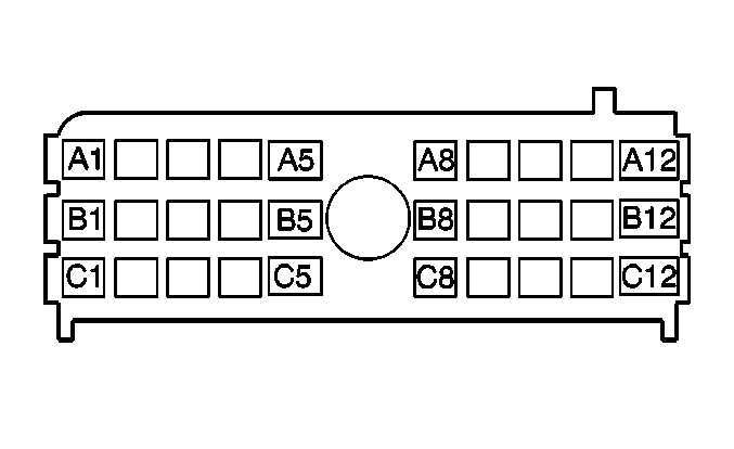
| |||||||
|---|---|---|---|---|---|---|---|
Connector Part Information |
| ||||||
Pin | Wire Color | Circuit No. | Function | ||||
A1 | -- | -- | Not Used | ||||
A2 | DK BLU | 15 | Right Front Turn Signal Lamp Positive Voltage | ||||
DK BLU | 15 | Right Front Turn Signal Lamp Positive Voltage | |||||
A3 | DK GRN | 117 | Right Front Speaker Output (-) | ||||
A4-A5 | -- | -- | Not Used | ||||
A8 | -- | -- | Not Used | ||||
A9 | BRN | 9 | Park Lamp Supply Voltage | ||||
BRN | 9 | Park Lamp Supply Voltage | |||||
A10 | -- | -- | Not Used | ||||
A11 | LT BLU | 20 | Stop Lamp Supply Voltage | ||||
A12 | GRY | 8 | Instrument Panel Lamp Supply Voltage 1 | ||||
GRY | 8 | Instrument Panel Lamp Supply Voltage 1 | |||||
B1 | BLK/WHT | 238 | Driver Seat Belt Switch Signal | ||||
B2 | LT BLU | 14 | Left Front Turn Signal Lamp Supply Voltage | ||||
LT BLU | 14 | Left Front Turn Signal Lamp Supply Voltage | |||||
B3 | DK BLU | 46 | Right Rear Speaker Output (+) | ||||
B4 | YEL | 116 | Left Rear Speaker Output (-) | ||||
B5 | WHT | 682 | Door Lock Lock/Unlock Signal | ||||
B8 | LT BLU | 395 | Passenger Door Ajar Switch Signal | ||||
B9 | BRN | 9 | Park Lamp Supply Voltage | ||||
B10 | -- | -- | Not Used | ||||
B11 | LT GRN | 24 | Backup Lamp Supply Voltage | ||||
B12 | GRY | 8 | Instrument Panel Lamp Supply Voltage 1 | ||||
C1 | LT GRN | 200 | Right Front Speaker Output (+) | ||||
C2 | -- | -- | Not Used | ||||
C3 | LT BLU | 115 | Right Rear Speaker Output (-) | ||||
C4 | BRN | 199 | Left Rear Speaker Output (+) | ||||
C5 | -- | -- | Not Used | ||||
C8 | -- | -- | Not Used | ||||
C9 | BRN | 9 | Park Lamps Supply Voltage | ||||
C10 | BRN | 9 | Park Lamps Supply Voltage | ||||
BRN | 9 | Park Lamps Supply Voltage | |||||
C11 | -- | -- | Not Used | ||||
C12 | GRY | 8 | Instrument Panel Lamps Supply Voltage 1 | ||||
GRY | 8 | Instrument Panel Lamps Supply Voltage 1 | |||||

| |||||||
|---|---|---|---|---|---|---|---|
Connector Part Information |
| ||||||
Pin | Wire Color | Circuit No. | Function | ||||
A1 | GRY | 8 | Instrument Panel Lamp Supply Voltage | ||||
A2 | LT BLU | 20 | Stop Lamp Supply Voltage | ||||
A3 | -- | -- | Not Used | ||||
A4 | BRN | 9 | Park Lamp Supply Voltage | ||||
A5 | -- | -- | Not Used | ||||
A8 | BRN | 141 | Ignition 3 Voltage | ||||
A9 | BRN | 341 | Ignition 3 Voltage | ||||
A10 | DK GRN | 117 | Right Front Speaker Output (-) | ||||
A11 | DK BLU | 15 | Right Front Turn Signal Lamp Positive Voltage | ||||
A12 | -- | -- | Not Used | ||||
B1 | GRY | 8 | Instrument Panel Lamp Supply Voltage | ||||
GRY | 8 | Instrument Panel Lamp Supply Voltage | |||||
B2 | LT GRN | 24 | Backup Lamp Supply Voltage | ||||
B3 | -- | -- | Not Used | ||||
B4 | BRN | 9 | Park Lamp Supply Voltage | ||||
B5 | LT BLU | 395 | Passenger Door Ajar Switch Signal | ||||
B8 | WHT | 682 | Door Lock/Unlock Signal | ||||
WHT | 682 | Door Lock/Unlock Signal | |||||
B9 | YEL | 116 | Left Rear Speaker Output (-) | ||||
B10 | DK BLU | 46 | Right Rear Speaker Output (-) | ||||
B11 | LT BLU | 14 | Left Front Turn Signal Lamp Positive Voltage | ||||
B12 | BLK/WHT | 238 | Driver Seat Belt Switch Signal | ||||
C1 | GRY | 8 | Instrument Panel Lamp Supply Voltage 1 | ||||
GRY | 8 | Instrument Panel Lamp Supply Voltage 1(CF5) | |||||
C2 | LT GRN | 24 | Backup Lamp Supply Voltage | ||||
C3 | -- | -- | Not Used | ||||
C4 | BRN | 9 | Park Lamp Supply Voltage | ||||
C5 | LT BLU | 395 | Passenger Door Ajar Switch Signal | ||||
LT BLU | 395 | Passenger Door Ajar Switch Signal | |||||
C8 | Not Used | ||||||
C9 | BRN | 199 | Left Rear Speaker Output (+) | ||||
C10 | LT BLU | 115 | Right Rear Speaker Output (-) | ||||
C11 | -- | -- | Not Used | ||||
C12 | LT GRN | 200 | Right Front Speaker Output (+) | ||||
