|
| ||||||||||||||
|---|---|---|---|---|---|---|---|---|---|---|---|---|---|---|---|
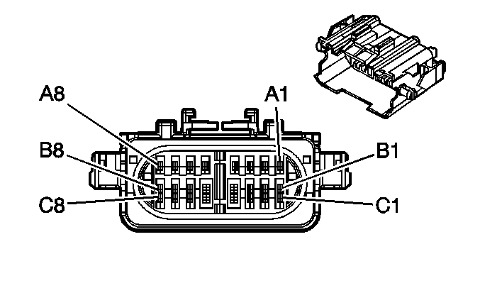
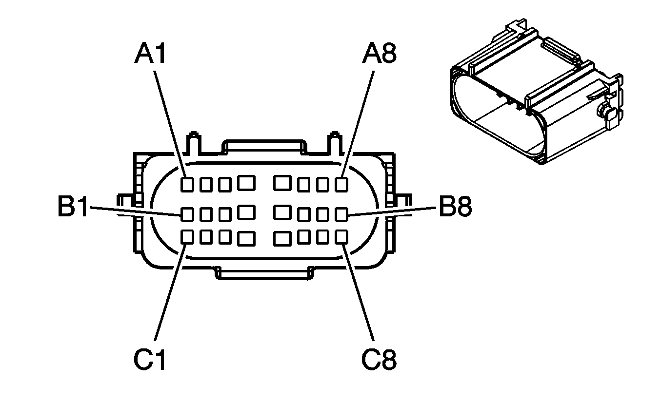
Connector Part Information |
| Connector Part Information |
| ||||||||||||
Pin | Wire Color | Circuit No. | Function | Pin | Wire Color | Circuit No. | Function | ||||||||
A1 | LT BLU | 72 | Medium 2 Blower Motor Control | A1 | LT BLU | 72 | Medium 2 Blower Motor Control | ||||||||
A2 | YEL | 60 | Blower Motor Low Control | A2 | YEL | 60 | Blower Motor Low Control | ||||||||
A3 | TAN | 63 | Blower Motor Medium 1 Control | A3 | TAN | 63 | Blower Motor Medium 1 Control | ||||||||
A4 | ORN | 52 | Blower Motor High Control | A4 | ORN | 52 | Blower Motor High Control | ||||||||
A5 | LT GRN | 66 | A/C Request Signal (C60) | A5 | LT GRN | 66 | A/C Request Signal | ||||||||
A6-A8 | -- | -- | Not Used | A6-A8 | -- | -- | Not Used | ||||||||
B1 | ORN | 1732 | Inadvertent Power Supply Voltage | B1 | ORN | 1732 | Inadvertent Power Supply Voltage | ||||||||
B2 | DK GRN | 1049 | Class 2 Serial Data | B2 | DK GRN | 1049 | Class 2 Serial Data | ||||||||
B3 | YEL | 710 | Class 2 Serial Data | B3 | YEL | 710 | Class 2 Serial Data | ||||||||
B4-B6 | -- | -- | Not Used | B4-B6 | -- | -- | Not Used | ||||||||
B7 | DK GRN/WHT | 817 | Vehicle Speed Signal | B7 | DK GRN/WHT | 817 | Vehicle Speed Signal (K34) | ||||||||
B8 | BRN/WHT | 419 | MIL Control | B8 | BRN/WHT | 419 | MIL Control | ||||||||
C1 | LT BLU/BLK | 396 | Cruise Control Engaged Signal | C1 | LT BLU/BLK | 396 | Cruise Control Engaged Signal (K34) | ||||||||
C2 | DK GRN | 83 | Cruise Control Inhibit Signal | C2 | DK GRN | 83 | Cruise Control Inhibit Signal (K34) | ||||||||
C3-C7 | -- | -- | Not Used | C3-C7 | -- | -- | Not Used | ||||||||
C8 | LT BLU | 1122 | Class 2 Serial Data | C8 | LT BLU | 1122 | Class 2 Serial Data | ||||||||
|
| ||||||||||||||
|---|---|---|---|---|---|---|---|---|---|---|---|---|---|---|---|
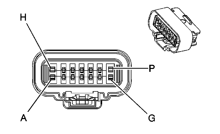
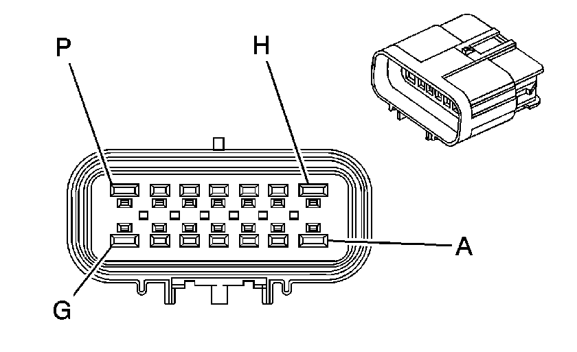
Connector Part Information |
| Connector Part Information |
| ||||||||||||
Pin | Wire Color | Circuit No. | Function | Pin | Wire Color | Circuit No. | Function | ||||||||
A | ORN | 52 | Blower Motor High Control | A | ORN | 52 | Blower Motor High Control | ||||||||
B | LT BLU | 72 | Medium 2 Blower Motor Control | B | LT BLU | 72 | Medium 2 Blower Motor Control | ||||||||
C | YEL | 60 | Blower Motor Low Control | C | YEL | 60 | Blower Motor Low Control | ||||||||
D | TAN | 63 | Blower Motor Medium 1 Control | D | TAN | 63 | Blower Motor Medium 1 Control | ||||||||
E | ORN | 1732 | Inadvertent Power Supply Voltage | E | ORN | 1732 | Inadvertent Power Supply Voltage | ||||||||
F | DK GRN | 1049 | Class 2 Serial Data | F | DK GRN | 1049 | Class 2 Serial Data | ||||||||
G | YEL | 710 | Class 2 Serial Data | G | YEL | 710 | Class 2 Serial Data | ||||||||
H | -- | -- | Not Used | H | -- | -- | Not Used | ||||||||
J | DK GRN/WHT | 817 | Vehicle Speed Signal (K34) | J | DK GRN/WHT | 817 | Vehicle Speed Signal | ||||||||
K | BRN/WHT | 419 | MIL Control | K | BRN/WHT | 419 | MIL Control | ||||||||
L | LT BLU/BLK | 396 | Cruise Control Engaged Signal (K34) | L | LT BLU/BLK | 396 | Cruise Control Engaged Signal | ||||||||
M | DK GRN | 83 | Cruise Control Inhibit Signal (K34) | M | DK GRN | 83 | Cruise Control Inhibit Signal | ||||||||
N | LT BLU | 1122 | Class 2 Serial Data | N | LT BLU | 1122 | Class 2 Serial Data | ||||||||
P | LT GRN | 66 | A/C Request Signal | P | LT GRN | 66 | A/C Request Signal (C60) | ||||||||
|
| ||||||||||||||
|---|---|---|---|---|---|---|---|---|---|---|---|---|---|---|---|
Connector Part Information |
| Connector Part Information |
| ||||||||||||
Pin | Wire Color | Circuit No. | Function | Pin | Wire Color | Circuit No. | Function | ||||||||
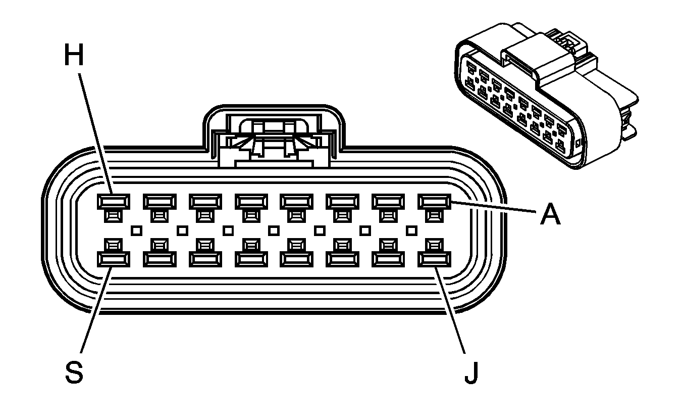
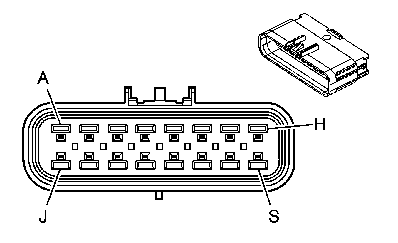
A | YEL/BLK | 1827 | Vehicle Speed Signal | A | YEL/BLK | 1827 | Vehicle Speed Signal | ||||||||
B | GRY | 2709 | 5 Volt Reference | B | GRY | 2709 | 5 Volt Reference | ||||||||
C | TAN | 2759 | Low Reference | C | TAN | 2759 | Low Reference | ||||||||
D | DK GRN | 890 | Fuel Tank Pressure Sensor Signal | D | DK GRN | 890 | Fuel Tank Pressure Sensor Signal | ||||||||
E | PPL | 333 | Brake Fluid Level Switch Signal (Heavy Duty) | E | PPL | 333 | Brake Fluid Level Switch Signal (Heavy Duty) | ||||||||
F | PPL | 1589 | Fuel Level Sensor Signal | F | PPL | 1589 | Fuel Level Sensor Signal | ||||||||
G | -- | -- | Not Used | G | -- | -- | Not Used | ||||||||
H | WHT | 1310 | EVAP Canister Vent Solenoid Control | H | WHT | 1310 | EVAP Canister Vent Solenoid Control | ||||||||
J | RED/WHT | 140 | Battery Positive Voltage | J | RED/WHT | 140 | Battery Positive Voltage | ||||||||
K | LT BLU | 1122 | Class 2 Serial Data | K | LT BLU | 1122 | Class 2 Serial Data | ||||||||
L-S | -- | -- | Not Used | L-S | -- | -- | Not Used | ||||||||
|
| ||||||||||||||
|---|---|---|---|---|---|---|---|---|---|---|---|---|---|---|---|
Connector Part Information |
| Connector Part Information |
| ||||||||||||
Pin | Wire Color | Circuit No. | Function | Pin | Wire Color | Circuit No. | Function | ||||||||
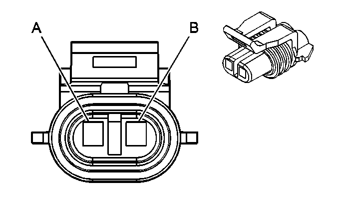
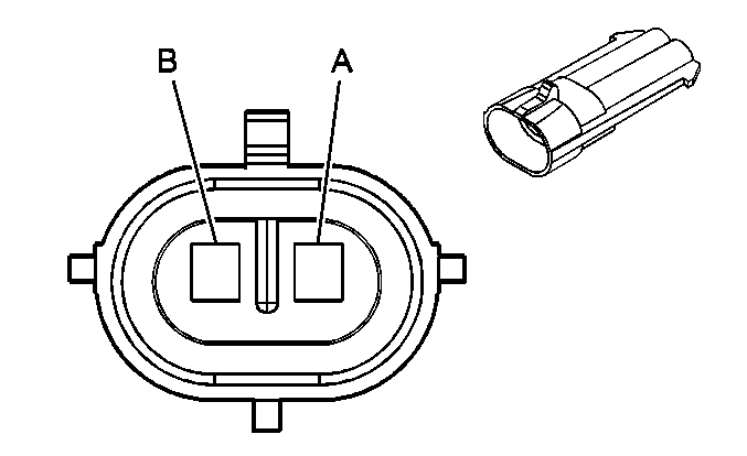
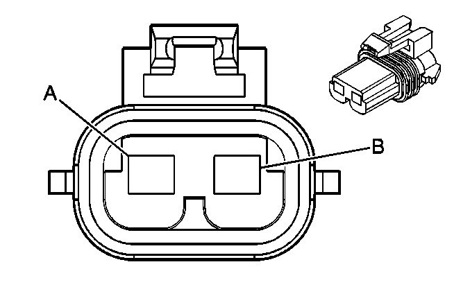
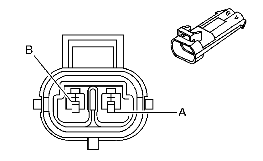
A | DK BLU | 496 | Knock Sensor 1 Signal | A | DK BLU | 496 | Knock Sensor 1 Signal | ||||||||
B | LT BLU | 1876 | Knock Sensor 2 Signal | B | LT BLU | 1876 | Knock Sensor 2 Signal | ||||||||
|
| ||||||||||||||
|---|---|---|---|---|---|---|---|---|---|---|---|---|---|---|---|
Connector Part Information |
| Connector Part Information |
| ||||||||||||
Pin | Wire Color | Circuit No. | Function | Pin | Wire Color | Circuit No. | Function | ||||||||
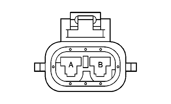
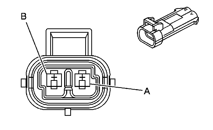
A | YEL | 354 | Front End Sensor - Signal | A | YEL | 354 | Front End Sensor - Signal | ||||||||
B | TAN/ORN | 5045 | Front End Sensor - Low Reference | B | TAN/ORN | 5045 | Front End Sensor - Low Reference | ||||||||
|
| ||||||||||||||
|---|---|---|---|---|---|---|---|---|---|---|---|---|---|---|---|
Connector Part Information |
| Connector Part Information |
| ||||||||||||
Pin | Wire Color | Circuit No. | Function | Pin | Wire Color | Circuit No. | Function | ||||||||
A | YEL | 354 | Front End Sensor - Signal | A | YEL | 354 | Front End Sensor - Signal | ||||||||
B | TAN/ORN | 5045 | Front End Sensor - Low Reference | B | TAN/ORN | 5045 | Front End Sensor - Low Reference | ||||||||

|

| ||||||||||||||
|---|---|---|---|---|---|---|---|---|---|---|---|---|---|---|---|
Connector Part Information |
| Connector Part Information |
| ||||||||||||
Pin | Wire Color | Circuit No. | Function | Pin | Wire Color | Circuit No. | Function | ||||||||
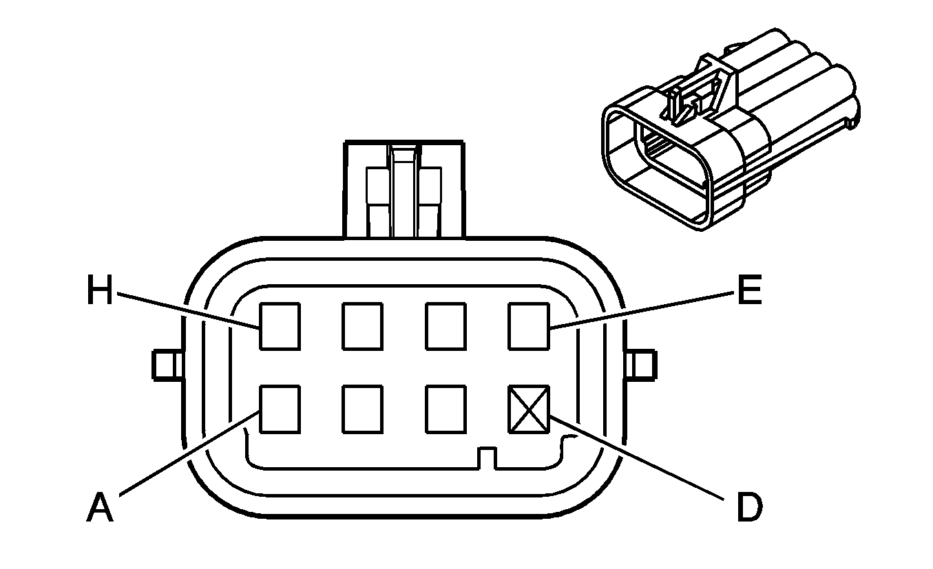
A | ORN | 1732 | Inadvertent Power Supply Voltage | A | ORN | 1732 | Inadvertent Power Supply Voltage | ||||||||
B | BLK | 1250 | Ground | B | BLK | 1250 | Ground | ||||||||
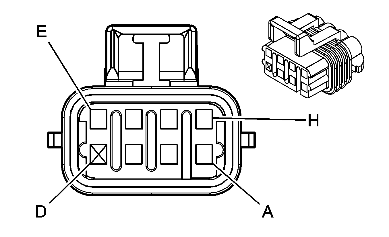
|
| ||||||||||||||
|---|---|---|---|---|---|---|---|---|---|---|---|---|---|---|---|
Connector Part Information |
| Connector Part Information |
| ||||||||||||
Pin | Wire Color | Circuit No. | Function | Pin | Wire Color | Circuit No. | Function | ||||||||
A | BLK | 1250 | Ground | A | BLK | 151 | Ground | ||||||||
B | ORN | 2127 | IC 7 Control | B | RED | 2127 | IC 7 Control | ||||||||
C | DK GRN | 2125 | IC 5 Control | C | DK GRN | 2125 | IC 5 Control | ||||||||
D | -- | -- | Not Used | D | -- | -- | Not Used | ||||||||
E | BRN | 2129 | Low Reference | E | BRN | 2129 | Low Reference | ||||||||
F | LT BLU | 2123 | IC 3 Control | F | LT BLU | 2123 | IC 3 Control | ||||||||
G | PPL | 2121 | IC 1 Control | G | PPL | 2121 | IC 1 Control | ||||||||
H | PNK | 139 | Ignition 1 Voltage | H | PNK | 39 | Ignition 1 Voltage | ||||||||

|

| ||||||||||||||
|---|---|---|---|---|---|---|---|---|---|---|---|---|---|---|---|
Connector Part Information |
| Connector Part Information |
| ||||||||||||
Pin | Wire Color | Circuit No. | Function | Pin | Wire Color | Circuit No. | Function | ||||||||
A | BLK | 1250 | Ground | A | BLK | 151 | Ground | ||||||||
B | ORN/WHT | 2122 | IC 2 Control | B | RED | 2122 | IC 2 Control | ||||||||
C | DK GRN/WHT | 2124 | IC 4 Control | C | DK GRN | 2124 | IC 4 Control | ||||||||
D | -- | -- | Not Used | D | -- | -- | Not Used | ||||||||
E | BRN/WHT | 2130 | Low Reference | E | BRN | 2129 | Low Reference | ||||||||
F | LT BLU/WHT | 2126 | IC 6 Control | F | LT BLU | 2126 | IC 6 Control | ||||||||
G | PPL/WHT | 2128 | IC 8 Control | G | PPL | 2128 | IC 8 Control | ||||||||
H | PNK | 239 | Ignition 1 Voltage | H | PNK | 39 | Ignition 1 Voltage | ||||||||
|
| ||||||||||||||
|---|---|---|---|---|---|---|---|---|---|---|---|---|---|---|---|
Connector Part Information |
| Connector Part Information |
| ||||||||||||
Pin | Wire Color | Circuit No. | Function | Pin | Wire Color | Circuit No. | Function | ||||||||
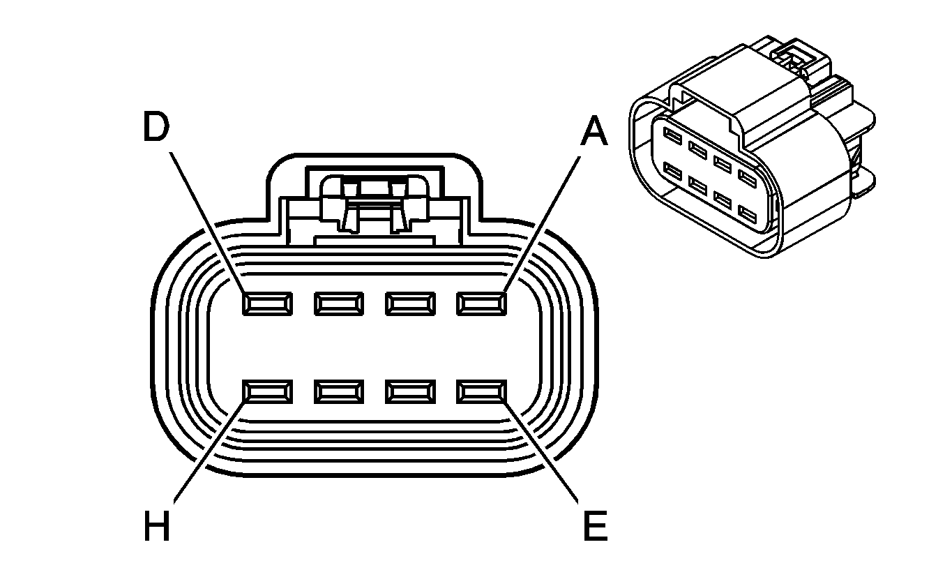
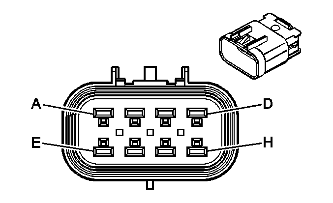
A | PPL/WHT | 1668 | HO2S High Signal - Bank 1 Sensor 2 | A | PPL/WHT | 1668 | HO2S High Signal - Bank 1 Sensor 2 | ||||||||
B | PNK | 1539 | Ignition 1 Voltage | B | PNK | 1539 | Ignition 1 Voltage | ||||||||
C | TAN/WHT | 1669 | HO2S Low Signal - Bank 1 Sensor 2 | C | TAN/WHT | 1669 | HO2S Low Signal - Bank 1 Sensor 2 | ||||||||
D | TAN | 1671 | HO2S Low Signal - Bank 2 Sensor 2 | D | TAN | 1671 | HO2S Low Signal - Bank 2 Sensor 2 | ||||||||
E | PPL | 1670 | HO2S High Signal - Bank 2 Sensor 2 | E | PPL | 1670 | HO2S High Signal - Bank 2 Sensor 2 | ||||||||
F | PNK | 1539 | Ignition 1 Voltage | F | PNK | 1539 | Ignition 1 Voltage | ||||||||
G | PPL | 5035 | HO2S Heater Low Control - Bank 1 Sensor 2 | G | PPL | 5035 | HO2S Heater Low Control - Bank 1 Sensor 2 | ||||||||
H | YEL | 5036 | HO2S Heater Low Control - Bank 2 Sensor 2 | H | YEL | 5036 | HO2S Heater Low Control - Bank 2 Sensor 2 | ||||||||

|

| ||||||||||||||
|---|---|---|---|---|---|---|---|---|---|---|---|---|---|---|---|
Connector Part Information |
| Connector Part Information |
| ||||||||||||
Pin | Wire Color | Circuit No. | Function | Pin | Wire Color | Circuit No. | Function | ||||||||
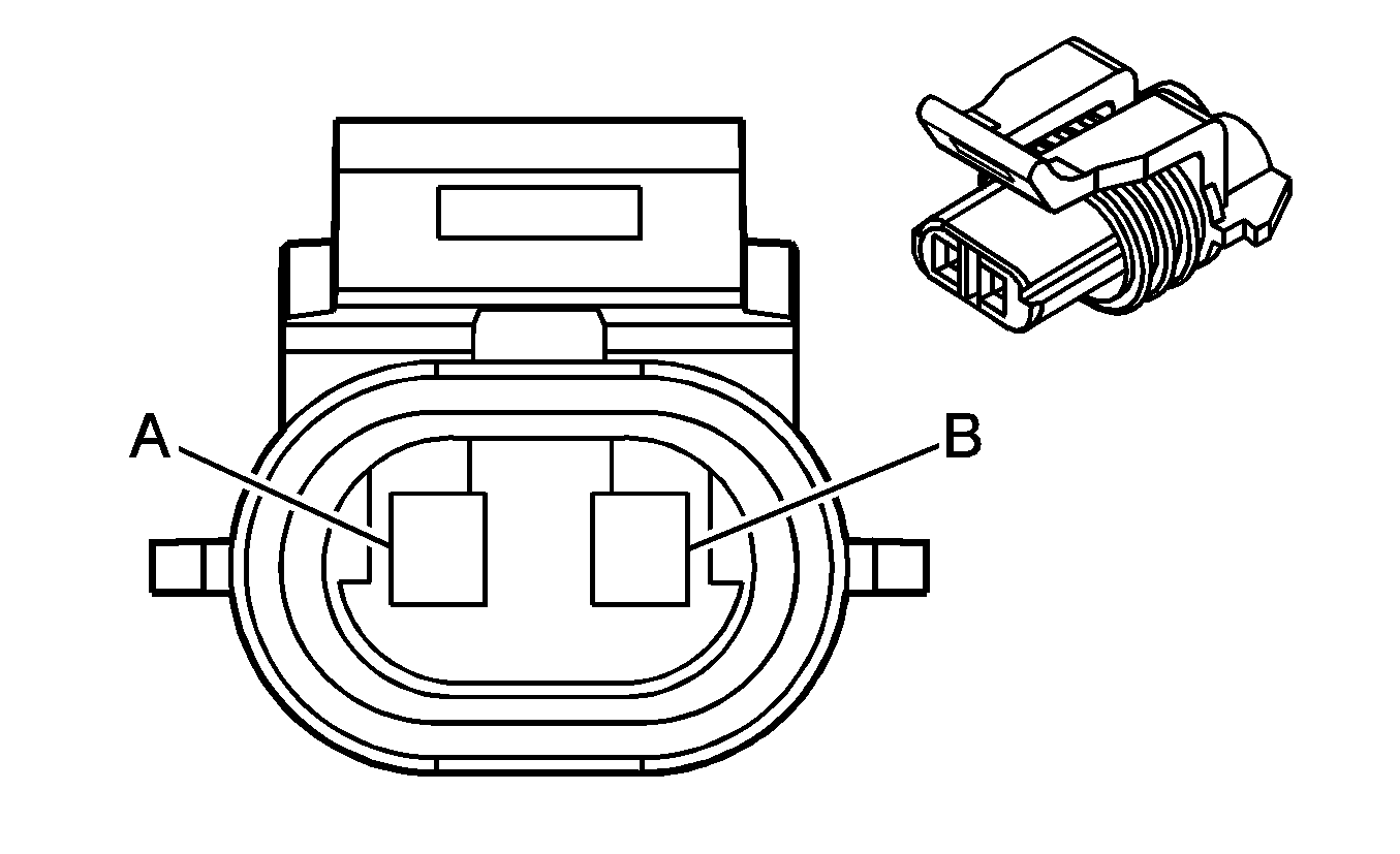
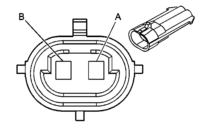
A | TAN/WHT | 33 | Brake Booster Fluid Switch Signal | A | TAN/WHT | 33 | Brake Booster Fluid Switch Signal | ||||||||
B | BLK | 350 | Ground | B | BLK | 350 | Ground | ||||||||
|
| ||||||||||||||
|---|---|---|---|---|---|---|---|---|---|---|---|---|---|---|---|
Connector Part Information |
| Connector Part Information |
| ||||||||||||
Pin | Wire Color | Circuit No. | Function | Pin | Wire Color | Circuit No. | Function | ||||||||
A | TAN/WHT | 33 | Brake Booster Fluid Switch Signal | A | TAN/WHT | 33 | Brake Booster Fluid Switch Signal | ||||||||
B | BLK | 350 | Ground | B | BLK | 350 | Ground | ||||||||
|
| ||||||||||||||
|---|---|---|---|---|---|---|---|---|---|---|---|---|---|---|---|
Connector Part Information |
| Connector Part Information |
| ||||||||||||
Pin | Wire Color | Circuit No. | Function | Pin | Wire Color | Circuit No. | Function | ||||||||
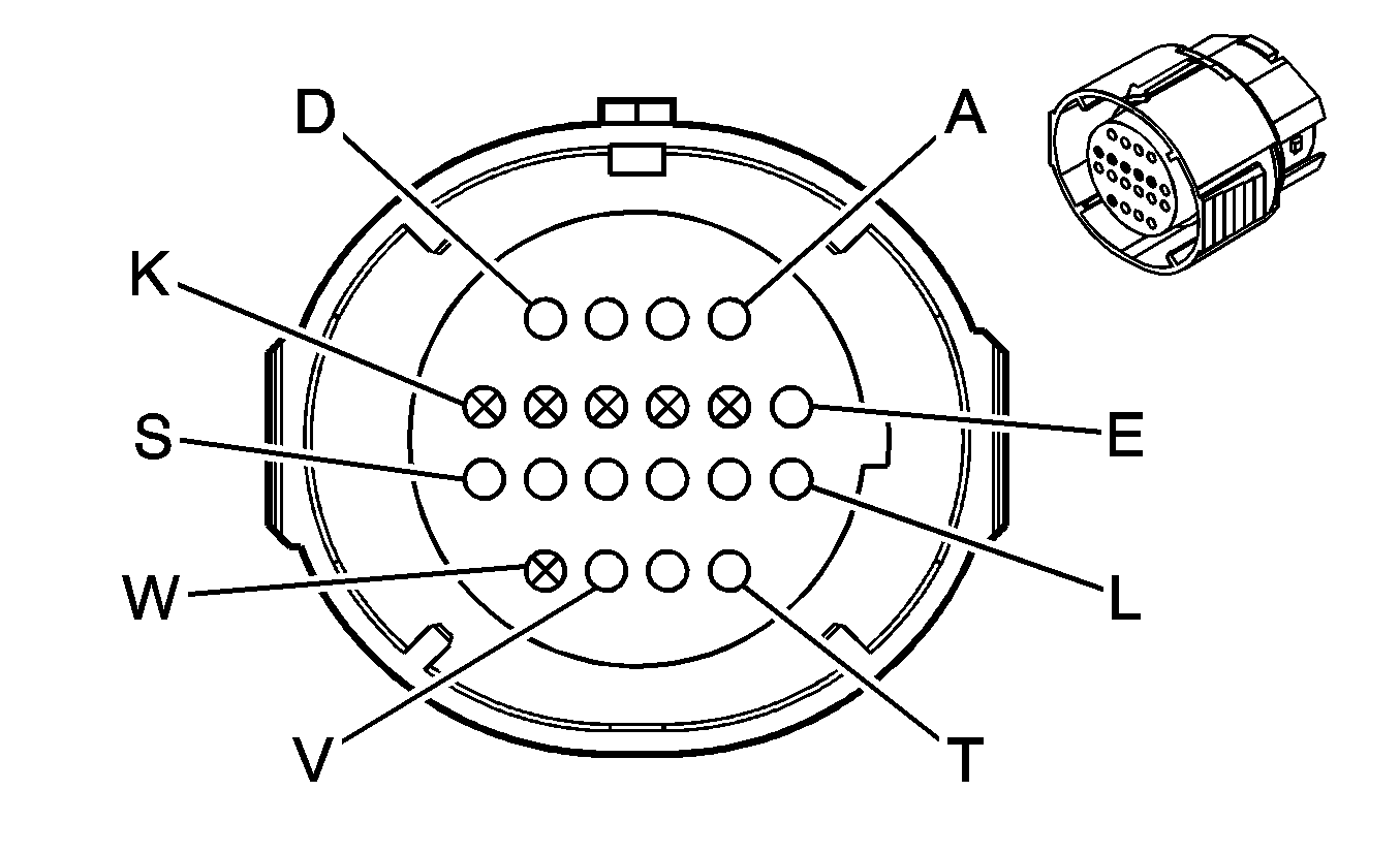
A | LT GRN | 1222 | 1-2 Shift Solenoid Valve Control | A | LT GRN | 1222 | 1-2 Shift Solenoid Valve Control | ||||||||
B | YEL/BLK | 1223 | 2-3 Shift Solenoid Valve Control | B | YEL | 1223 | 2-3 Shift Solenoid Valve Control | ||||||||
C | ORN/BLK | 1228 | PC Solenoid Valve High Control | C | PPL | 1228 | PC Solenoid Valve High Control | ||||||||
D | LT BLU/WHT | 1229 | PC Solenoid Valve Low Control | D | LT BLU | 1229 | PC Solenoid Valve Low Control | ||||||||
E | PNK | 1020 | Ignition 0 Voltage | E | RED | 839 | Ignition 1 Voltage | ||||||||
F-K | -- | -- | Not Used | F-K | -- | -- | Not Used | ||||||||
L | YEL/BLK | 1227 | TFT Sensor Signal | L | BRN | 1227 | TFT Sensor Signal | ||||||||
M | TAN | 2762 | Low Reference | M | GRY | 452 | Low Reference | ||||||||
N | PNK | 1224 | Transmission Fluid Pressure Switch Signal A | N | PNK | 1224 | Transmission Fluid Pressure Switch Signal A | ||||||||
P | ORN | 1226 | Transmission Fluid Pressure Switch Signal C | P | ORN | 1226 | Transmission Fluid Pressure Switch Signal C | ||||||||
R | DK BLU | 1225 | Transmission Fluid Pressure Switch Signal B | R | DK BLU | 1225 | Transmission Fluid Pressure Switch Signal B | ||||||||
S | WHT | 687 | 3-2 Shift Solenoid Valve Control | S | WHT | 687 | 3-2 Shift Solenoid Valve Control | ||||||||
T | TAN/BLK | 422 | TCC Solenoid Valve Control | T | BLK | 422 | TCC Solenoid Valve Control | ||||||||
U | BRN | 418 | TCC PWM Solenoid Valve Control | U | TAN | 418 | TCC PWM Solenoid Valve Control | ||||||||
V-W | -- | -- | Not Used | V-W | -- | -- | Not Used | ||||||||

|

| ||||||||||||||
|---|---|---|---|---|---|---|---|---|---|---|---|---|---|---|---|
Connector Part Information |
| Connector Part Information |
| ||||||||||||
Pin | Wire Color | Circuit No. | Function | Pin | Wire Color | Circuit No. | Function | ||||||||
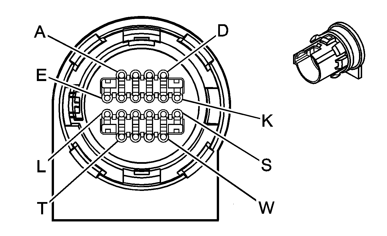
A | LT GRN | 1222 | 1-2 Shift Solenoid Valve Control | A | LT GRN | 1222 | 1-2 Shift Solenoid Valve Control | ||||||||
B | YEL/BLK | 1223 | 2-3 Shift Solenoid Valve Control | B | YEL | 1223 | 2-3 Shift Solenoid Valve Control | ||||||||
C | ORN/BLK | 1228 | PC Solenoid Valve High Control | C | PPL | 1228 | PC Solenoid Valve High Control | ||||||||
D | LT BLU/WHT | 1229 | PC Solenoid Valve Low Control | D | LT BLU | 1229 | PC Solenoid Valve Low Control | ||||||||
E | PNK | 1020 | Ignition 0 Voltage | E | RED | 839 | Ignition 1 Voltage | ||||||||
F-K | -- | -- | Not Used | F-K | -- | -- | Not Used | ||||||||
L | YEL/BLK | 1227 | TFT Sensor Signal | L | BRN | 1227 | TFT Sensor Signal | ||||||||
M | TAN | 2762 | Low Reference | M | GRY | 452 | Low Reference | ||||||||
N | PNK | 1224 | Transmission Fluid Pressure Switch Signal A | N | PNK | 1224 | Transmission Fluid Pressure Switch Signal A | ||||||||
P | ORN | 1226 | Transmission Fluid Pressure Switch Signal C | P | ORN | 1226 | Transmission Fluid Pressure Switch Signal C | ||||||||
R | DK BLU | 1225 | Transmission Fluid Pressure Switch Signal B | R | DK BLU | 1225 | Transmission Fluid Pressure Switch Signal B | ||||||||
S | BRN | 418 | TCC PWM Solenoid Valve Control | S | BLK | 418 | TCC PWM Solenoid Valve Control | ||||||||
T-W | -- | -- | Not Used | T-W | -- | -- | Not Used | ||||||||
|
| ||||||||||||||
|---|---|---|---|---|---|---|---|---|---|---|---|---|---|---|---|
Connector Part Information |
| Connector Part Information |
| ||||||||||||
Pin | Wire Color | Circuit No. | Function | Pin | Wire Color | Circuit No. | Function | ||||||||
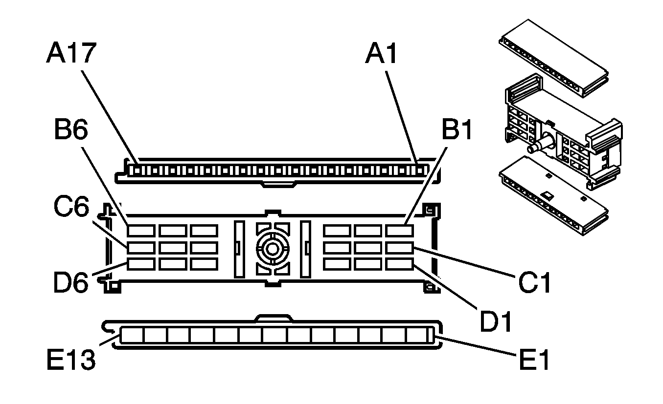
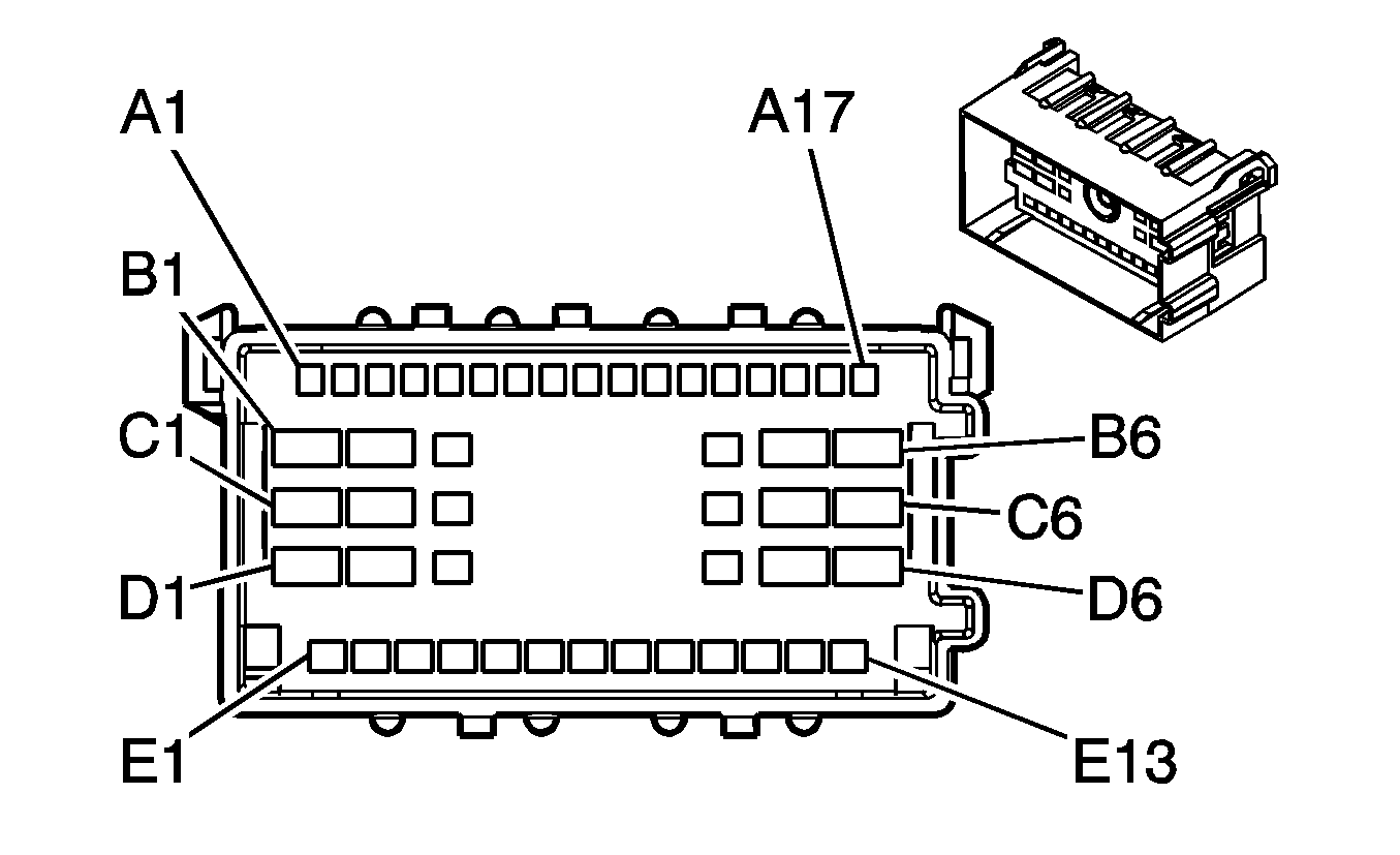
A1 | TAN | 28 | Horn Relay Control | A1 | TAN | 28 | Horn Relay Control | ||||||||
A2-A3 | -- | -- | Not Used | A2-A3 | -- | -- | Not Used | ||||||||
A4 | DK BLU/WHT | 1415 | Right Turn Signal Switch Signal | A4 | DK BLU/WHT | 1415 | Right Turn Signal Switch Signal | ||||||||
A5 | LT BLU/WHT | 1414 | Left Turn Signal Switch Signal | A5 | LT BLU/WHT | 1414 | Left Turn Signal Switch Signal | ||||||||
A6-A10 | -- | -- | Not Used | A6-A10 | -- | -- | Not Used | ||||||||
A11 | LT GRN | 80 | Key In Ignition Switch Signal | A11 | LT GRN | 80 | Key In Ignition Switch Signal | ||||||||
A12-A17 | -- | -- | Not Used | A12-A17 | -- | -- | Not Used | ||||||||
B1-B3 | -- | -- | Not Used | B1-B3 | -- | -- | Not Used | ||||||||
B4 | WHT | 111 | Hazard Switch Signal | B4 | WHT | 111 | Hazard Switch Signal | ||||||||
WHT | 111 | Hazard Switch Signal | |||||||||||||
B5 | RED/BLK | 142 | Battery Positive Voltage | B5 | RED/BLK | 142 | Battery Positive Voltage | ||||||||
B6 | BRN | 4 | Accessory Voltage | B6 | BRN | 4 | Accessory Voltage | ||||||||
C1 | YEL | 5 | Crank Voltage | C1 | YEL | 5 | Crank Voltage | ||||||||
C2 | -- | -- | Not Used | C2 | -- | -- | Not Used | ||||||||
C3 | ORN/WHT | 812 | 12 Volt Reference | C3 | ORN/WHT | 812 | 12 Volt Reference | ||||||||
C4 | TAN | 1835 | Security System Sensor Low Reference | C4 | TAN | 1835 | Security System Sensor Low Reference | ||||||||
C5 | WHT | 1390 | Accy/Run/Start Voltage | C5 | WHT | 1390 | Accy/Run/Start Voltage | ||||||||
C6 | PNK | 3 | Ignition 1 Voltage | C6 | PNK | 3 | Ignition 1 Voltage | ||||||||
D1 | ORN | 300 | Ignition 3 Voltage | D1 | ORN | 300 | Ignition 3 Voltage | ||||||||
D2 | RED/BLK | 342 | Battery Positive Voltage | D2 | RED/BLK | 342 | Battery Positive Voltage | ||||||||
D3 | YEL | 1836 | Security System Sensor Signal | D3 | YEL | 1836 | Security System Sensor Signal | ||||||||
D4-D6 | -- | -- | Not Used | D4-D6 | -- | -- | Not Used | ||||||||
E1 | BLK | 350 | Ground | E1 | BLK | 350 | Ground | ||||||||
E2 | -- | -- | Not Used | E2 | -- | -- | Not Used | ||||||||
E3 | GRY/BLK | 87 | Cruise Control Resume/Accel Switch Signal (K34) | E3 | GRY/BLK | 87 | Cruise Control Resume/Accel Switch Signal (K34) | ||||||||
E4 | PNK | 94 | Windshield Washer Switch Signal 1 | E4 | PNK | 94 | Windshield Washer Switch Signal 1 | ||||||||
E5 | DK BLU | 477 | Windshield Wiper Switch High Signal | E5 | DK BLU | 477 | Windshield Wiper Switch High Signal | ||||||||
E6 | -- | -- | Not Used | E6 | -- | -- | Not Used | ||||||||
E7 | DK GRN/WHT | 1135 | A/T Shift Lock Control Solenoid Supply Voltage | E7 | DK GRN/WHT | 1135 | A/T Shift Lock Control Solenoid Supply Voltage | ||||||||
E8 | GRY | 478 | Windshield Wiper Switch Supply Voltage | E8 | GRY | 478 | Windshield Wiper Switch Supply Voltage | ||||||||
E9 | GRY | 397 | Cruise Control On Switch Signal (K34) | E9 | GRY | 397 | Cruise Control On Switch Signal (K34) | ||||||||
E10 | DK BLU | 84 | Cruise Control Set/Coast Switch Signal (K34) | E10 | DK BLU | 84 | Cruise Control Set/Coast Switch Signal (K34) | ||||||||
E11 | YEL | 307 | Headlamp Switch Flash to Pass Signal | E11 | YEL | 307 | Headlamp Switch Flash to Pass Signal | ||||||||
E12 | LT GRN | 11 | Headlamp Dimmer Switch Signal | E12 | LT GRN | 11 | Headlamp Dimmer Switch Signal | ||||||||
E13 | PNK | 739 | Ignition 1 Voltage | E13 | PNK | 739 | Ignition 1 Voltage | ||||||||
PNK | 739 | Ignition 1 Voltage (K34) | |||||||||||||
|
| ||||||||||||||
|---|---|---|---|---|---|---|---|---|---|---|---|---|---|---|---|
Connector Part Information |
| Connector Part Information |
| ||||||||||||
Pin | Wire Color | Circuit No. | Function | Pin | Wire Color | Circuit No. | Function | ||||||||
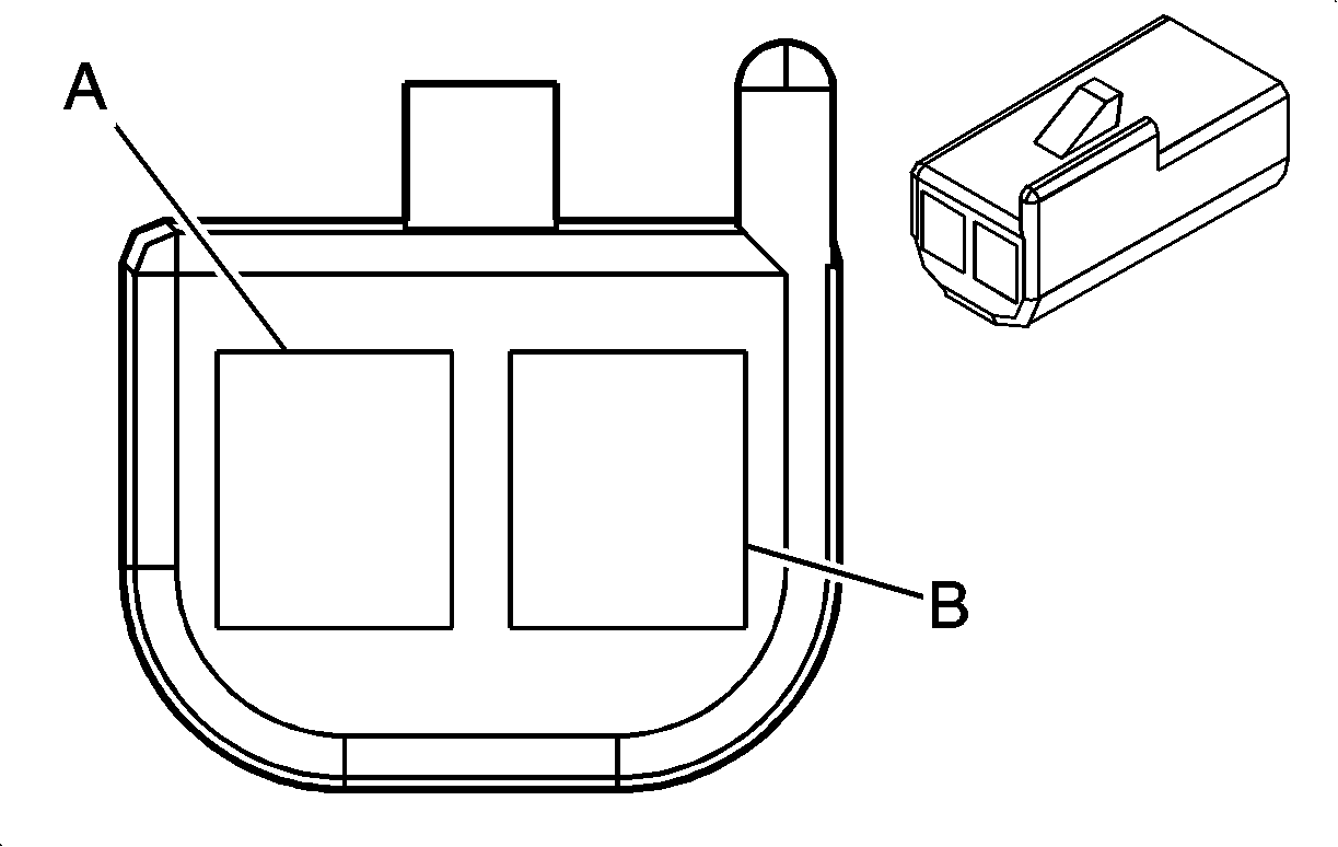
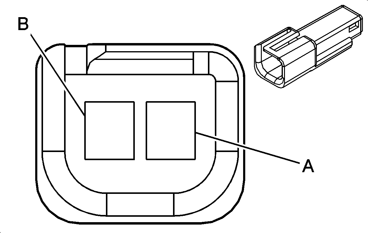
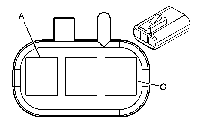
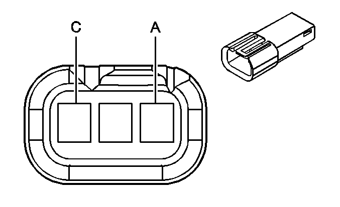
A | ORN | 1732 | Inadvertent Power Supply Voltage | A | ORN | 1732 | Inadvertent Power Supply Voltage | ||||||||
B | BLK | 450 | Ground | B | BLK | 450 | Ground | ||||||||
|
| ||||||||||||||
|---|---|---|---|---|---|---|---|---|---|---|---|---|---|---|---|
Connector Part Information |
| Connector Part Information |
| ||||||||||||
Pin | Wire Color | Circuit No. | Function | Pin | Wire Color | Circuit No. | Function | ||||||||
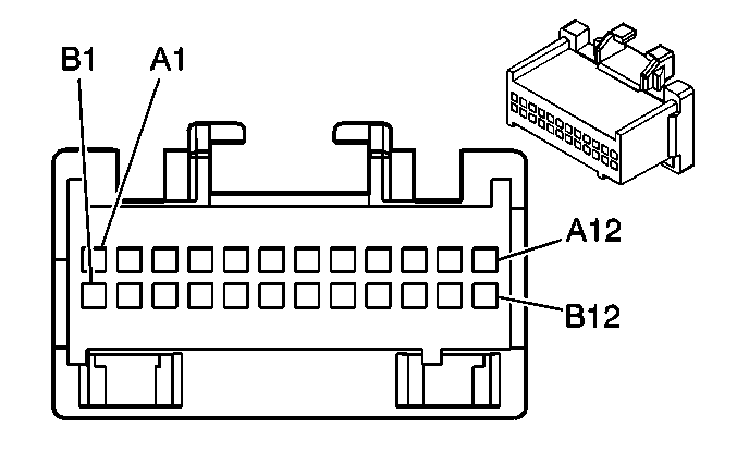
A | LT BLU | 195 | Access Panel Left Side Front Relay Control | A | LT BLU | 244 | Access Panel Left Side Front Relay Control | ||||||||
B | LT GRN | 1391 | Access Panel Left Side Rear Relay Control | B | LT GRN | 1391 | Access Panel Left Side Rear Relay Control | ||||||||
C | LT BLU | 1344 | Access Panel Right Side Relay Control | C | LT BLU | 1344 | Access Panel Right Side Relay Control | ||||||||
|
| ||||||||||||||
|---|---|---|---|---|---|---|---|---|---|---|---|---|---|---|---|
Connector Part Information |
| Connector Part Information |
| ||||||||||||
Pin | Wire Color | Circuit No. | Function | Pin | Wire Color | Circuit No. | Function | ||||||||
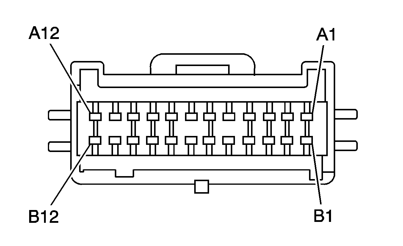
A1-A2 | -- | -- | Not Used | A1-A2 | -- | -- | Not Used | ||||||||
A3 | LT BLU | 244 | Door Unlock Control (AU3) | A3 | WHT | 194 | Door Unlock Control (AU3) | ||||||||
A4 | PNK/WHT | 1970 | Headlamp Low Beam Relay Control | A4 | PNK/WHT | 1970 | Headlamp Low Beam Relay Control | ||||||||
A5 | WHT | 111 | Hazard Switch Signal | A5 | WHT | 111 | Hazard Switch Signal | ||||||||
A6 | DK BLU | 245 | Door Lock Control (AU3) | A6 | LT BLU | 195 | Door Lock Control (AU3) | ||||||||
A7 | LT GRN | 1391 | Door Unlock Control (AU3) | A7 | WHT | 194 | Door Unlock Control (AU3) | ||||||||
A8 | LT BLU | 1344 | Door Unlock Control (AU3) | A8 | WHT | 194 | Door Unlock Control (AU3) | ||||||||
A9-A10 | -- | -- | Not Used | A9-A10 | -- | -- | Not Used | ||||||||
A11 | ORN/WHT | 812 | 12 Volt Reference | A11 | ORN/WHT | 812 | 12 Volt Reference | ||||||||
A12 | RED/WHT | 1140 | Battery Positive Voltage | A12 | RED/WHT | 1140 | Battery Positive Voltage | ||||||||
B1 | TAN/WHT | 1969 | Headlamp High Beam Relay Control | B1 | TAN/WHT | 1969 | Headlamp High Beam Relay Control | ||||||||
B2 | WHT | 1080 | Park Lamp Relay Control | B2 | WHT | 1080 | Park Lamp Relay Control | ||||||||
B3 | TAN | 755 | RAP Relay Coil Control (A31) | B3 | TAN | 755 | RAP Relay Coil Control (A31) | ||||||||
B4 | LT GRN/BLK | 592 | DRL Low Control | B4 | LT GRN/BLK | 592 | DRL Low Control | ||||||||
B5 | -- | -- | Not Used | B5 | -- | -- | Not Used | ||||||||
B6 | BLK/WHT | 351 | Ground | B6 | BLK/WHT | 351 | Ground | ||||||||
B7 | TAN | 1835 | Security System Sensor Low Reference | B7 | TAN | 1835 | Security System Sensor Low Reference | ||||||||
B8 | PNK | 1348 | Headlamp On Indicator Supply Voltage | B8 | PNK | 1348 | Headlamp On Indicator Supply Voltage | ||||||||
B9 | TAN | 28 | Horn Relay Control | B9 | TAN | 28 | Horn Relay Control | ||||||||
B10 | -- | -- | Not Used | B10 | -- | -- | Not Used | ||||||||
B11 | GRY | 705 | 5 Volt Reference | B11 | GRY | 705 | 5 Volt Reference | ||||||||
B12 | LT GRN | 1037 | Class 2 Serial Data | B12 | LT GRN | 1037 | Class 2 Serial Data | ||||||||
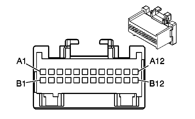
|
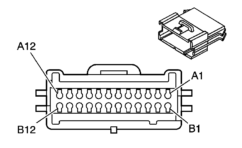
| ||||||||||||||
|---|---|---|---|---|---|---|---|---|---|---|---|---|---|---|---|
Connector Part Information |
| Connector Part Information |
| ||||||||||||
Pin | Wire Color | Circuit No. | Function | Pin | Wire Color | Circuit No. | Function | ||||||||
A1 | LT GRN | 80 | Key In Ignition Switch Signal | A1 | LT GRN | 80 | Key In Ignition Switch Signal | ||||||||
A2 | YEL | 307 | Headlamp Switch Flash to Pass Signal | A2 | YEL | 307 | Headlamp Switch Flash to Pass Signal | ||||||||
A3 | PNK | 1020 | Ignition 0 Voltage | A3 | PNK | 1020 | Ignition 0 Voltage | ||||||||
A4 | PNK | 39 | Ignition 1 Voltage | A4 | PNK | 39 | Ignition 1 Voltage | ||||||||
A5 | LT GRN | 1177 | Door Open Switch Signal | A5 | LT GRN | 1177 | Door Open Switch Signal | ||||||||
A6 | -- | -- | Not Used | A6 | -- | -- | Not Used | ||||||||
A7 | LT BLU | 1134 | Park Brake Switch Signal | A7 | LT BLU | 1134 | Park Brake Switch Signal | ||||||||
A8-A9 | -- | -- | Not Used | A8-A9 | -- | -- | Not Used | ||||||||
A10 | YEL/BLK | 1181 | Rear Door Open Switch Signal | A10 | YEL/BLK | 1181 | Rear Door Open Switch Signal | ||||||||
A11 | -- | -- | Not Used | A11 | -- | -- | Not Used | ||||||||
A12 | WHT | 103 | Headlamp Switch Headlamps On Signal | A12 | WHT | 103 | Headlamp Switch Headlamps On Signal | ||||||||
B1-B2 | -- | -- | Not Used | B1-B2 | -- | -- | Not Used | ||||||||
B3 | YEL | 343 | Accessory Voltage | B3 | YEL | 343 | Accessory Voltage | ||||||||
B4 | TAN | 126 | Left Front Door Open Switch Signal | B4 | TAN | 126 | Left Front Door Open Switch Signal | ||||||||
B5 | LT BLU | 195 | Door Lock Control (AU3) | B5 | LT BLU | 195 | Door Lock Control (AU3) | ||||||||
B6 | GRY/BLK | 2226 | Dimming Return | B6 | GRY/BLK | 2226 | Dimming Return | ||||||||
B7-B8 | -- | -- | Not Used | B7-B8 | -- | -- | Not Used | ||||||||
B9 | DK BLU/WHT | 1495 | Courtesy Lamps On Signal | B9 | DK BLU/WHT | 1495 | Courtesy Lamps On Signal | ||||||||
B10 | WHT | 194 | Door Unlock Control (AU3) | B10 | WHT | 194 | Door Unlock Control (AU3) | ||||||||
B11-B12 | -- | -- | Not Used | B11-B12 | -- | -- | Not Used | ||||||||
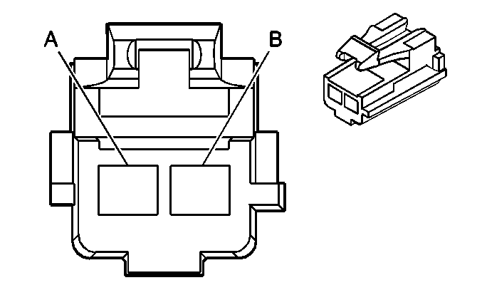
|
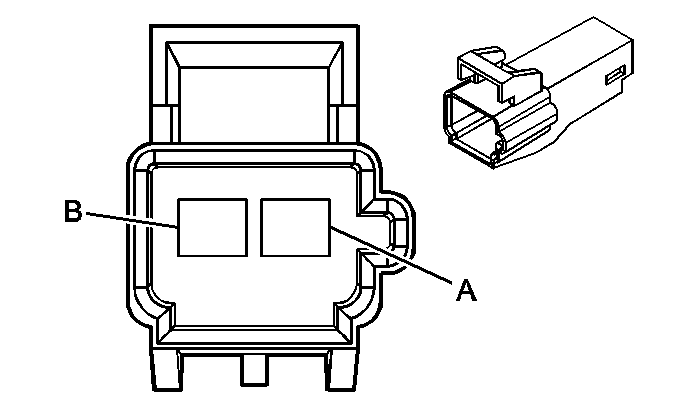
| ||||||||||||||
|---|---|---|---|---|---|---|---|---|---|---|---|---|---|---|---|
Connector Part Information |
| Connector Part Information |
| ||||||||||||
Pin | Wire Color | Circuit No. | Function | Pin | Wire Color | Circuit No. | Function | ||||||||
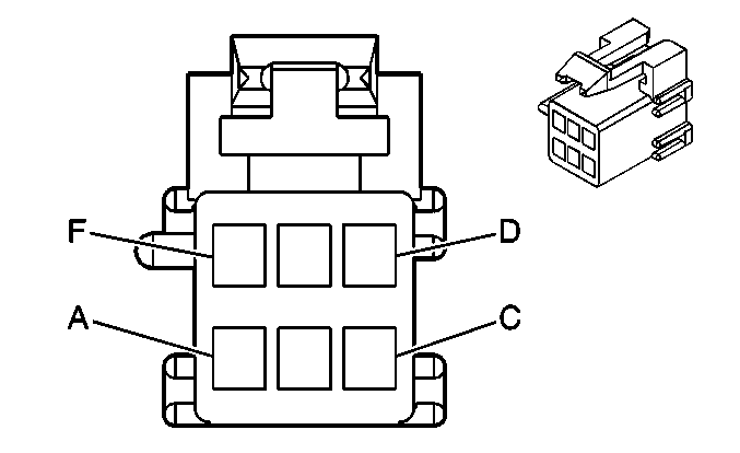
A | LT BLU | 1134 | Park Brake Switch Signal | A | LT BLU | 1134 | Park Brake Switch Signal | ||||||||
B | -- | -- | Not Used | B | -- | -- | Not Used | ||||||||
|
| ||||||||||||||
|---|---|---|---|---|---|---|---|---|---|---|---|---|---|---|---|
Connector Part Information |
| Connector Part Information |
| ||||||||||||
Pin | Wire Color | Circuit No. | Function | Pin | Wire Color | Circuit No. | Function | ||||||||
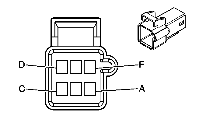
A | WHT | 17 | Stop Lamp Switch Signal | A | WHT | 17 | Stop Lamp Switch Signal | ||||||||
B | RED/WHT | 1540 | Battery Positive Voltage | B | RED/WHT | 1540 | Battery Positive Voltage | ||||||||
C | PNK | 739 | Ignition 1 Voltage | C | PNK | 739 | Ignition 1 Voltage | ||||||||
D | PPL | 420 | TCC Brake Switch/Cruise Control Release Signal | D | PPL | 420 | TCC Brake Switch/Cruise Control Release Signal | ||||||||
E | LT GRN/BLK | 584 | A/T Shift Lock Control Switch Supply Voltage | E | LT GRN/BLK | 584 | A/T Shift Lock Control Switch Supply Voltage | ||||||||
F | DK GRN/WHT | 1135 | A/T Shift Lock Control Solenoid Supply Voltage | F | DK GRN/WHT | 1135 | A/T Shift Lock Control Solenoid Supply Voltage | ||||||||
-- |
| ||||||||||
|---|---|---|---|---|---|---|---|---|---|---|---|
Connector Part Information | Upfitter Supplied | Connector Part Information |
| ||||||||
Pin | Wire Color | Circuit No. | Function | Pin | Wire Color | Circuit No. | Function | ||||
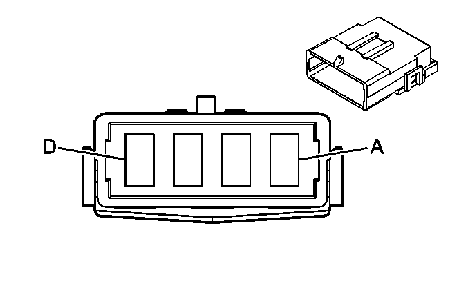
A | -- | -- | Upfitter Usage | A | RED/BLK | 1042 | Battery Positive Voltage | ||||
B | -- | -- | Upfitter Usage | B | BRN | 541 | Ignition 3 Voltage | ||||
C | -- | -- | Upfitter Usage | C | BLK | 350 | Ground | ||||
D | -- | -- | Upfitter Usage | D | -- | -- | Not Used | ||||
|
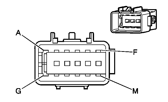
| ||||||||||||||
|---|---|---|---|---|---|---|---|---|---|---|---|---|---|---|---|
Connector Part Information |
| Connector Part Information |
| ||||||||||||
Pin | Wire Color | Circuit No. | Function | Pin | Wire Color | Circuit No. | Function | ||||||||
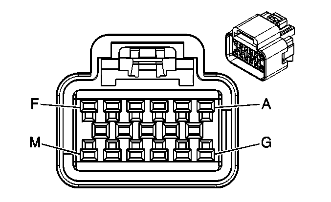
A | PNK | 1439 | Ignition 1 Voltage (DF5) | A | PNK | 1439 | Ignition 1 Voltage (DF5) | ||||||||
B | LT GRN | 24 | Backup Lamp Supply Voltage (DF5) | B | LT GRN | 24 | Backup Lamp Supply Voltage (DF5) | ||||||||
C | PPL | 679 | Keypad Signal (UE1) | C | PPL | 679 | Keypad Signal (UE1) | ||||||||
D | GRY/BLK | 1798 | Keypad Green LED Signal (UE1) | D | GRY/BLK | 1798 | Keypad Green LED Signal (UE1) | ||||||||
E | PPL | 1156 | Keypad Red LED Signal (UE1) | E | PPL | 1156 | Keypad Red LED Signal (UE1) | ||||||||
F | DK GRN/WHT | 636 | Ambient Air Temperature Sensor Signal (DF5) | F | DK GRN/WHT | 636 | Ambient Air Temperature Sensor Signal (DF5) | ||||||||
G | TAN/WHT | 1704 | Low Reference (DF5) | G | TAN/WHT | 1704 | Low Reference (DF5) | ||||||||
H | BRN | 1941 | Keypad Supply Voltage (UE1) | H | BRN | 1941 | Keypad Supply Voltage (UE1) | ||||||||
J | GRY | 655 | Cellular Microphone Signal (UE1) | J | GRY | 655 | Cellular Microphone Signal (UE1) | ||||||||
K | BARE | 1782 | Drain Wire (UE1) | K | BARE | 1782 | Drain Wire (UE1) | ||||||||
L | BLK | 550 | Ground (DF5/UE1) | L | BLK | 550 | Ground (DF5/UE1) | ||||||||
M | -- | -- | Not Used | M | -- | -- | Not Used | ||||||||
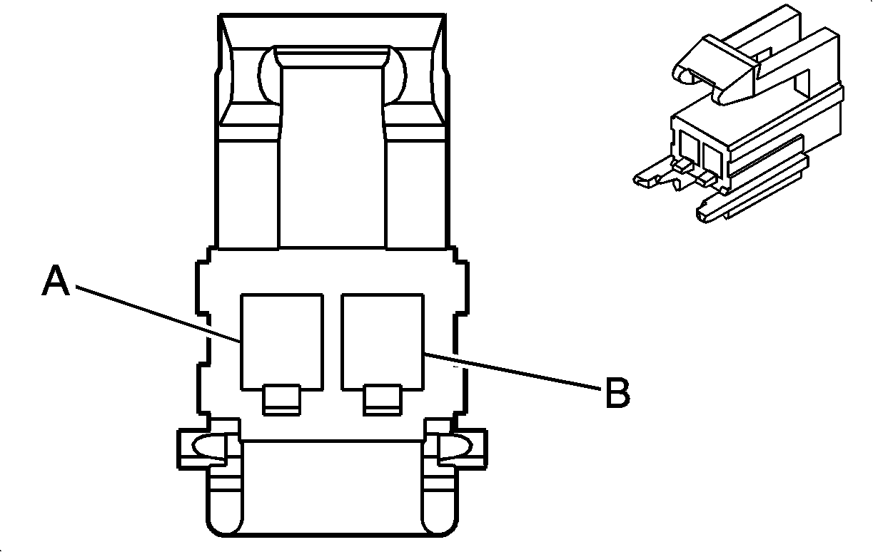
|
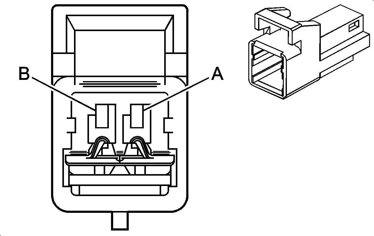
| ||||||||||||||
|---|---|---|---|---|---|---|---|---|---|---|---|---|---|---|---|
Connector Part Information |
| Connector Part Information |
| ||||||||||||
Pin | Wire Color | Circuit No. | Function | Pin | Wire Color | Circuit No. | Function | ||||||||
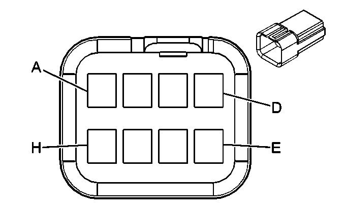
A | LT GRN | 2116 | Seat Belt Pretensioner - Right - High Control | A | LT GRN | 2116 | Seat Belt Pretensioner - Right - High Control | ||||||||
B | ORN | 2117 | Seat Belt Pretensioner - Right - Low Control | B | ORN | 2117 | Seat Belt Pretensioner - Right - Low Control | ||||||||
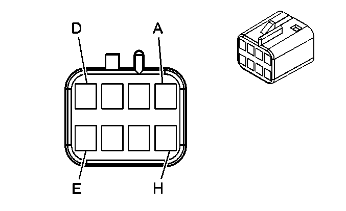
|
| ||||||||||||||
|---|---|---|---|---|---|---|---|---|---|---|---|---|---|---|---|
Connector Part Information |
| Connector Part Information |
| ||||||||||||
Pin | Wire Color | Circuit No. | Function | Pin | Wire Color | Circuit No. | Function | ||||||||
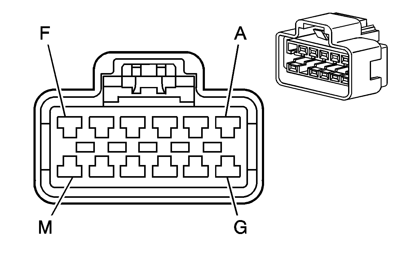
A | WHT | 1924 | Auxiliary Blower Motor High Control | A | WHT | 1924 | Auxiliary Blower Motor High Control | ||||||||
B | ORN | 1925 | Auxiliary Blower Motor Medium Control | B | ORN | 1925 | Auxiliary Blower Motor Medium Control | ||||||||
C | DK BLU | 1926 | Auxiliary Blower Motor Low Control | C | DK BLU | 1926 | Auxiliary Blower Motor Low Control | ||||||||
D | ORN | 2775 | Auxiliary Air Temperature Door Control | D | ORN | 2775 | Auxiliary Air Temperature Door Control | ||||||||
E | GRY | 2599 | Auxiliary Mode Door Control | E | GRY | 2599 | Auxiliary Mode Door Control | ||||||||
F | BRN/WHT | 230 | Instrument Panel Lamps Dimming Control | F | BRN/WHT | 230 | Instrument Panel Lamps Dimming Control | ||||||||
G | BRN | 341 | Ignition 3 Voltage | G | BRN | 341 | Ignition 3 Voltage | ||||||||
H | BLK | 450 | Ground | H | BLK | 450 | Ground | ||||||||
|
| ||||||||||||||
|---|---|---|---|---|---|---|---|---|---|---|---|---|---|---|---|
Connector Part Information |
| Connector Part Information |
| ||||||||||||
Pin | Wire Color | Circuit No. | Function | Pin | Wire Color | Circuit No. | Function | ||||||||
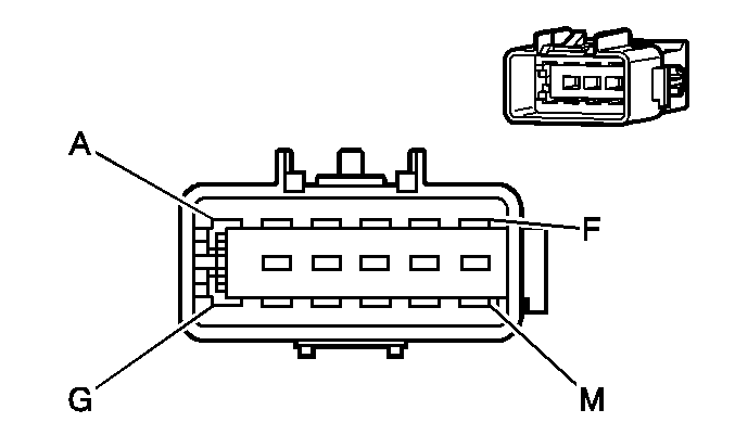
A | BRN | 341 | Ignition 3 Voltage (C69) | A | BRN | 341 | Ignition 3 Voltage (C69) | ||||||||
B | BRN/WHT | 230 | Instrument Panel Lamps Dimming Control (C69) | B | BRN/WHT | 230 | Instrument Panel Lamps Dimming Control (C69) | ||||||||
C | BLK | 450 | Ground | C | BLK | 450 | Ground | ||||||||
D | ORN | 2775 | Auxiliary Air Temperature Door Control (C69) | D | ORN | 2775 | Auxiliary Air Temperature Door Control (C69) | ||||||||
E | GRY | 2599 | Auxiliary Mode Door Control (C69) | E | GRY | 2599 | Auxiliary Mode Door Control (C69) | ||||||||
F | DK BLU/WHT | 149 | Courtesy Lamp Supply Voltage | F | DK BLU/WHT | 149 | Courtesy Lamp Supply Voltage | ||||||||
G | ORN | 1732 | Inadvertent Power Supply Voltage | G | ORN | 1732 | Inadvertent Power Supply Voltage | ||||||||
H | WHT | 1924 | Auxiliary Blower Motor High Control (Rear Auxiliary Controls) | H | WHT | 1924 | Auxiliary Blower Motor High Control (Rear Auxiliary Controls) | ||||||||
J | ORN | 1925 | Auxiliary Blower Motor Medium Control (Rear Auxiliary Controls) | J | ORN | 1925 | Auxiliary Blower Motor Medium Control (Rear Auxiliary Controls) | ||||||||
K | DK BLU | 1926 | Auxiliary Blower Motor Low Control (Rear Auxiliary Controls) | K | DK BLU | 1926 | Auxiliary Blower Motor Low Control (Rear Auxiliary Controls) | ||||||||
L-M | -- | -- | Not Used | L-M | -- | -- | Not Used | ||||||||

|
| ||||||||||||||
|---|---|---|---|---|---|---|---|---|---|---|---|---|---|---|---|
Connector Part Information |
| Connector Part Information |
| ||||||||||||
Pin | Wire Color | Circuit No. | Function | Pin | Wire Color | Circuit No. | Function | ||||||||
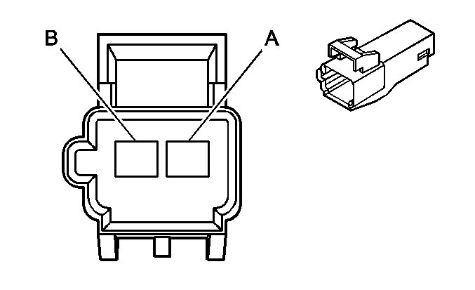
A | BLK | 450 | Ground | A | BLK | 450 | Ground (AG2) | ||||||||
B | RED/WHT | 3540 | Battery Positive Voltage | B | RED/WHT | 3540 | Battery Positive Voltage (AG2) | ||||||||

|

| ||||||||||||||
|---|---|---|---|---|---|---|---|---|---|---|---|---|---|---|---|
Connector Part Information |
| Connector Part Information |
| ||||||||||||
Pin | Wire Color | Circuit No. | Function | Pin | Wire Color | Circuit No. | Function | ||||||||
A-F | -- | -- | Not Used | A-F | -- | -- | Not Used | ||||||||
G | PNK | 5017 | Low Reference | G | PNK | 5017 | Low Reference | ||||||||
H | LT BLU | 5056 | Seat Position Sensor - Right - Signal | H | LT BLU | 5056 | Seat Position Sensor - Right - Signal | ||||||||
J | BLK | 450 | Ground (AG1/AG2) | J | BLK | 450 | Ground (AG2) | ||||||||
K | RED/WHT | 3540 | Battery Positive Voltage (AG1/AG2) | K | RED/WHT | 3540 | Battery Positive Voltage (AG2) | ||||||||
L-M | -- | -- | Not Used | L-M | -- | -- | Not Used | ||||||||
|
| ||||||||||||||
|---|---|---|---|---|---|---|---|---|---|---|---|---|---|---|---|
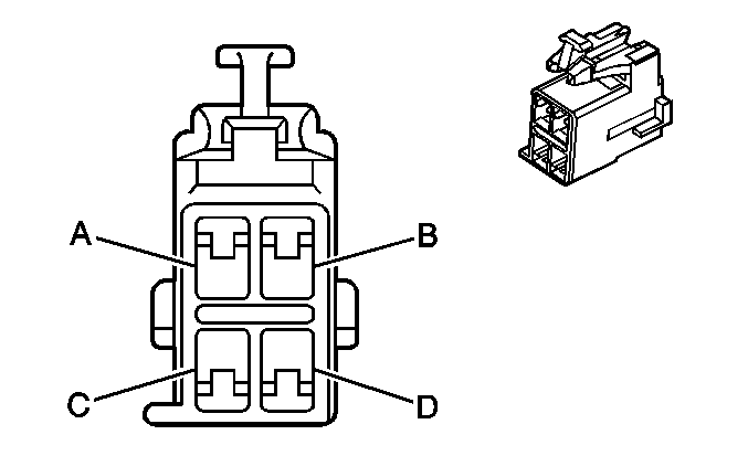
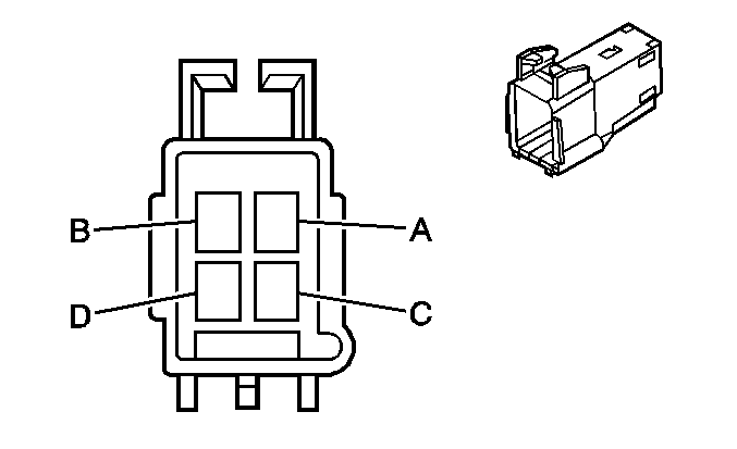
Connector Part Information |
| Connector Part Information |
| ||||||||||||
Pin | Wire Color | Circuit No. | Function | Pin | Wire Color | Circuit No. | Function | ||||||||
A | -- | -- | Not Used | A | -- | -- | Not Used | ||||||||
B | TAN/WHT | 238 | Left Seat Belt Switch Signal | B | TAN/WHT | 238 | Left Seat Belt Switch Signal | ||||||||
C | BLK | 450 | Ground | C | BLK | 450 | Ground | ||||||||
D | RED/WHT | 3540 | Battery Positive Voltage (AG1/AG2) | D | RED/WHT | 3540 | Battery Positive Voltage (AG1) | ||||||||
|
| ||||||||||||||
|---|---|---|---|---|---|---|---|---|---|---|---|---|---|---|---|
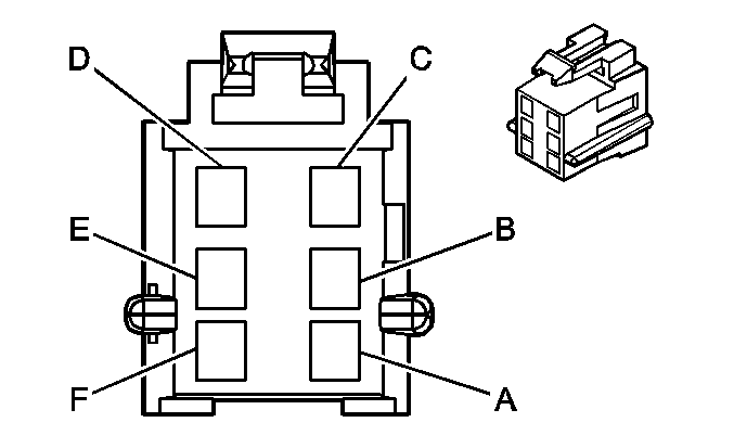
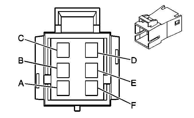
Connector Part Information |
| Connector Part Information |
| ||||||||||||
Pin | Wire Color | Circuit No. | Function | Pin | Wire Color | Circuit No. | Function | ||||||||
A | LT GRN | 5055 | Seat Position Sensor - Left - Signal | A | LT GRN | 5055 | Seat Position Sensor - Left - Signal | ||||||||
B | PNK | 5017 | Low Reference | B | PNK | 5017 | Low Reference | ||||||||
C | TAN/WHT | 238 | Left Seat Belt Switch Signal | C | TAN/WHT | 238 | Left Seat Belt Switch Signal | ||||||||
D | BLK | 450 | Ground | D | BLK | 450 | Ground | ||||||||
E | RED/WHT | 3540 | Battery Positive Voltage (AG1/AG2) | E | RED/WHT | 3540 | Battery Positive Voltage (AG1) | ||||||||
F | -- | -- | Not Used | F | -- | -- | Not Used | ||||||||
|
| ||||||||||||||
|---|---|---|---|---|---|---|---|---|---|---|---|---|---|---|---|
Connector Part Information |
| Connector Part Information |
| ||||||||||||
Pin | Wire Color | Circuit No. | Function | Pin | Wire Color | Circuit No. | Function | ||||||||
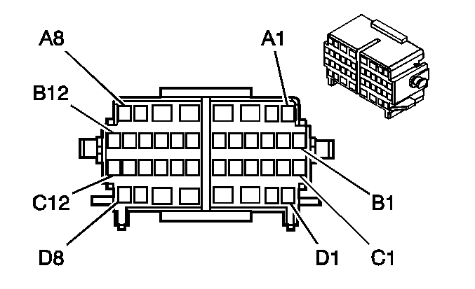
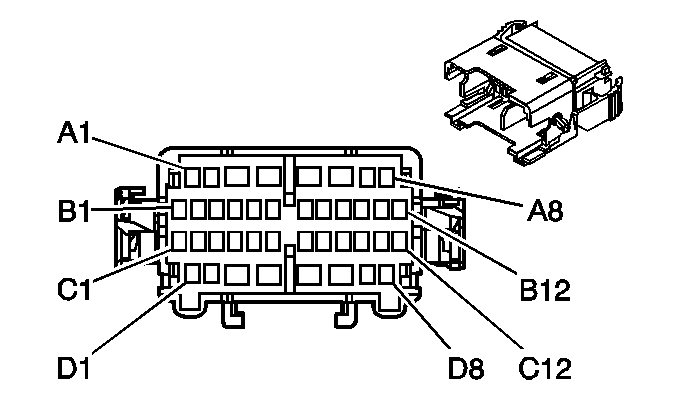
A1 | TAN | 126 | Left Front Door Open Switch Signal | A1 | TAN | 126 | Left Front Door Open Switch Signal | ||||||||
A2 | LT BLU | 1957 | Left Front Midrange Speaker Output (-) | A2 | LT BLU | 1957 | Left Front Midrange Speaker Output (-) | ||||||||
A3 | BLK | 450 | Ground | A3 | BLK | 450 | Ground | ||||||||
A4 | TAN | 694 | Driver Door Lock Actuator Unlock Control (AU3) | A4 | TAN | 694 | Driver Door Lock Actuator Unlock Control (AU3) | ||||||||
A5 | WHT | 193 | Rear Defog Relay Supply Voltage (DE5/DE7) | A5 | WHT | 193 | Rear Defog Relay Supply Voltage (DE5/DE7) | ||||||||
A6 | BRN/WHT | 230 | Instrument Panel Lamps Dimming Control (AU3) | A6 | BRN/WHT | 230 | Instrument Panel Lamps Dimming Control (AU3/A31) | ||||||||
BRN/WHT | 230 | Instrument Panel Lamps Dimming Control (A31) | |||||||||||||
A7-A8 | -- | -- | Not Used | A7-A8 | -- | -- | Not Used | ||||||||
B1 | WHT | 194 | Door Unlock Control (AU3) | B1 | WHT | 194 | Door Unlock Control (AU3) | ||||||||
B2 | LT BLU | 195 | Door Lock Control (AU3) | B2 | LT BLU | 195 | Door Lock Control (AU3) | ||||||||
B3-B12 | -- | -- | Not Used | B3-B12 | -- | -- | Not Used | ||||||||
C1-C7 | -- | -- | Not Used | C1-C7 | -- | -- | Not Used | ||||||||
C8 | ORN | 4340 | Battery Positive Voltage (DE5/DE7) | C8 | ORN | 4340 | Battery Positive Voltage (DE5/DE7) | ||||||||
C9 | DK BLU | 1857 | Left Front Midrange Speaker Output (+) | C9 | DK BLU | 1857 | Left Front Midrange Speaker Output (+) | ||||||||
C10 | YEL/BLK | 1334 | Left Mirror Turn Signal Lamp Supply Voltage (DE7) | C10 | YEL/BLK | 1334 | Left Mirror Turn Signal Lamp Supply Voltage (DE7) | ||||||||
C11-C12 | -- | -- | Not Used | C11-C12 | -- | -- | Not Used | ||||||||
D1 | PPL/WHT | 889 | Passenger Mirror Motor Up Control (DE5/DE7) | D1 | PPL/WHT | 889 | Passenger Mirror Motor Up Control (DE5/DE7) | ||||||||
D2 | -- | -- | Not Used | D2 | -- | -- | Not Used | ||||||||
D3 | WHT | 1185 | Power Window Switch Left Rear Up Signal (A31) | D3 | WHT | 1185 | Power Window Switch Left Rear Up Signal (A31) | ||||||||
D4 | ORN | 1189 | Power Window Switch Right Front Low Reference (A31) | D4 | ORN | 1189 | Power Window Switch Right Front Low Reference (A31) | ||||||||
D5 | GRY | 295 | Door Lock Actuator Lock Control (AU3) | D5 | GRY | 295 | Door Lock Actuator Lock Control (AU3) | ||||||||
D6 | DK GRN | 1001 | RAP Fuse Supply Voltage (A31) | D6 | DK GRN | 1001 | RAP Fuse Supply Voltage (A31) | ||||||||
D7 | BRN/WHT | 1498 | Passenger Mirror Motor Down/Right Control (DE5/DE7) | D7 | BRN/WHT | 1498 | Passenger Mirror Motor Down/Right Control (DE5/DE7) | ||||||||
D8 | ORN/WHT | 881 | Passenger Mirror Motor Left Control (DE5/DE7) | D8 | ORN/WHT | 881 | Passenger Mirror Motor Left Control (DE5/DE7) | ||||||||
|
| ||||||||||||||
|---|---|---|---|---|---|---|---|---|---|---|---|---|---|---|---|
Connector Part Information |
| Connector Part Information |
| ||||||||||||
Pin | Wire Color | Circuit No. | Function | Pin | Wire Color | Circuit No. | Function | ||||||||
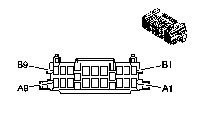
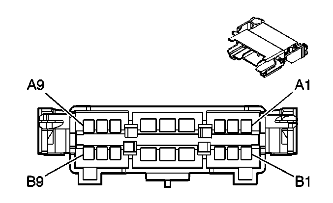
A1 | LT GRN | 1177 | Door Open Switch Signal | A1 | LT GRN | 1177 | Door Open Switch Signal | ||||||||
A2 | -- | -- | Not Used | A2 | -- | -- | Not Used | ||||||||
A3 | TAN | 294 | Door Lock Actuator Unlock Control (AU3) | A3 | TAN | 294 | Door Lock Actuator Unlock Control (AU3) | ||||||||
A4 | WHT | 193 | Rear Defog Relay Supply Voltage (DE5/DE7) | A4 | WHT | 193 | Rear Defog Relay Supply Voltage (DE5/DE7) | ||||||||
A5 | BRN/WHT | 230 | Instrument Panel Lamps Dimming Control (AU3) | A5 | BRN/WHT | 230 | Instrument Panel Lamps Dimming Control (AU3/A31) | ||||||||
BRN/WHT | 230 | Instrument Panel Lamps Dimming Control (A31) | |||||||||||||
A6 | BRN/WHT | 1498 | Passenger Mirror Motor Down/Right Control (DE5/DE7) | A6 | BRN/WHT | 1498 | Passenger Mirror Motor Down/Right Control (DE5/DE7) | ||||||||
BRN/WHT | 1498 | Passenger Mirror Motor Down/Right Control (DE5/DE7) | |||||||||||||
A7 | PPL/WHT | 889 | Passenger Mirror Motor Up Control (DE5/DE7) | A7 | PPL/WHT | 889 | Passenger Mirror Motor Up Control (DE5/DE7) | ||||||||
A8 | GRY | 295 | Door Lock Actuator Lock Control (AU3) | A8 | GRY | 295 | Door Lock Actuator Lock Control (AU3) | ||||||||
A9 | WHT | 194 | Door Unlock Control (AU3) | A9 | WHT | 194 | Door Unlock Control (AU3) | ||||||||
B1 | LT BLU | 195 | Door Lock Control (AU3) | B1 | LT BLU | 195 | Door Lock Control (AU3) | ||||||||
B2 | DK GRN/WHT | 1335 | Right Mirror Turn Signal Lamp Supply Voltage (DE7) | B2 | DK GRN/WHT | 1335 | Right Mirror Turn Signal Lamp Supply Voltage (DE7) | ||||||||
B3 | BLK | 450 | Ground | B3 | BLK | 450 | Ground | ||||||||
B4 | DK GRN | 1001 | RAP Fuse Supply Voltage (A31) | B4 | DK GRN | 1001 | RAP Fuse Supply Voltage (A31) | ||||||||
B5 | WHT | 1185 | Power Window Switch Left Rear Up Signal (A31) | B5 | WHT | 1185 | Power Window Switch Left Rear Up Signal (A31) | ||||||||
B6 | ORN | 1189 | Power Window Switch Right Front Low Reference (A31) | B6 | ORN | 1189 | Power Window Switch Right Front Low Reference (A31) | ||||||||
B7 | DK GRN | 1953 | Right Front Midrange Speaker Output (-) | B7 | DK GRN | 1953 | Right Front Midrange Speaker Output (-) | ||||||||
B8 | ORN | 1853 | Right Front Midrange Speaker Output (+) | B8 | ORN | 1853 | Right Front Midrange Speaker Output (+) | ||||||||
B9 | ORN/WHT | 881 | Passenger Mirror Motor Left Control (DE5/DE7) | B9 | ORN/WHT | 881 | Passenger Mirror Motor Left Control (DE5/DE7) | ||||||||
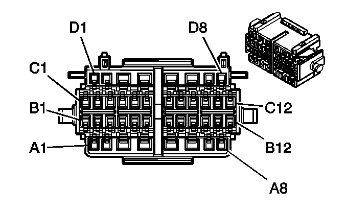
|
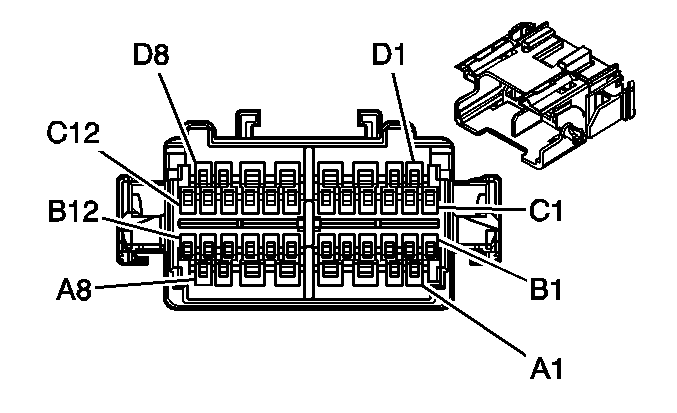
| ||||||||||||||
|---|---|---|---|---|---|---|---|---|---|---|---|---|---|---|---|
Connector Part Information |
| Connector Part Information |
| ||||||||||||
Pin | Wire Color | Circuit No. | Function | Pin | Wire Color | Circuit No. | Function | ||||||||
A1 | LT BLU | 1957 | Left Front Midrange Speaker Output (-) | A1 | LT BLU | 1957 | Left Front Midrange Speaker Output (-) | ||||||||
A2 | DK BLU | 1857 | Left Front Midrange Speaker Output (+) | A2 | DK BLU | 1857 | Left Front Midrange Speaker Output (+) | ||||||||
A3 | DK GRN | 1953 | Right Front Midrange Speaker Output (-) | A3 | DK GRN | 1953 | Right Front Midrange Speaker Output (-) | ||||||||
A4 | ORN | 1853 | Right Front Midrange Speaker Output (+) | A4 | ORN | 1853 | Right Front Midrange Speaker Output (+) | ||||||||
A5 | WHT | 1959 | Left Rear Midrange Speaker Output (-) | A5 | WHT | 1959 | Left Rear Midrange Speaker Output (-) | ||||||||
A6 | TAN | 1859 | Left Rear Midrange Speaker Output (+) | A6 | TAN | 1859 | Left Rear Midrange Speaker Output (+) | ||||||||
A7 | ORN | 1955 | Right Rear Midrange Speaker Output (-) | A7 | ORN | 1955 | Right Rear Midrange Speaker Output (-) | ||||||||
A8 | TAN | 1855 | Right Rear Midrange Speaker Output (+) | A8 | TAN | 1855 | Right Rear Midrange Speaker Output (+) | ||||||||
B1 | -- | -- | Not Used | B1 | -- | -- | Not Used | ||||||||
B2 | PNK | 5017 | Low Reference (Light Duty) | B2 | PNK | 5017 | Low Reference (Light Duty) | ||||||||
B3 | LT GRN | 5055 | Seat Position Sensor - Left - Signal (Light Duty) | B3 | LT GRN | 5055 | Seat Position Sensor - Left - Signal (Light Duty) | ||||||||
B4 | TAN/WHT | 238 | Left Seat Belt Switch Signal | B4 | TAN/WHT | 238 | Left Seat Belt Switch Signal | ||||||||
B5-B10 | -- | -- | Not Used | B5-B10 | -- | -- | Not Used | ||||||||
B11 | PPL | 493 | Rear Seat Audio Enable Signal (UK6) | B11 | PPL | 493 | Rear Seat Audio Enable Signal (UK6) | ||||||||
B12 | LT GRN | 1011 | Remote Radio Control Signal (UK6) | B12 | LT GRN | 1011 | Remote Radio Control Signal (UK6) | ||||||||
C1 | PPL | 1375 | Remote Radio Control Supply Voltage (UK6) | C1 | PPL | 1375 | Remote Radio Control Supply Voltage (UK6) | ||||||||
C2 | BLK/WHT | 351 | Ground (UK6) | C2 | BLK/WHT | 351 | Ground (UK6) | ||||||||
C3-C10 | -- | -- | Not Used | C3-C10 | -- | -- | Not Used | ||||||||
C11 | LT BLU | 5056 | Seat Position Sensor - Right - Signal (Light Duty) | C11 | LT BLU | 5056 | Seat Position Sensor - Right - Signal (Light Duty) | ||||||||
C12 | -- | -- | Not Used | C12 | -- | -- | Not Used | ||||||||
D1 | -- | -- | Not Used | D1 | -- | -- | Not Used | ||||||||
D2 | TAN | 126 | Left Front Door Open Switch Signal | D2 | TAN | 126 | Left Front Door Open Switch Signal | ||||||||
D3 | LT GRN | 24 | Backup Lamp Supply Voltage | D3 | LT GRN | 24 | Backup Lamp Supply Voltage | ||||||||
LT GRN | 24 | Backup Lamp Supply Voltage (Cargo or Passenger w/DF5) | |||||||||||||
D4 | YEL/BLK | 1181 | Rear Door Open Switch Signal (Passenger/Cargo) | D4 | YEL/BLK | 1181 | Rear Door Open Switch Signal (Passenger/Cargo) | ||||||||
YEL/BLK | 1181 | Rear Door Open Switch Signal (E26) | |||||||||||||
D5 | ORN | 1732 | Inadvertent Power Supply Voltage | D5 | ORN | 1732 | Inadvertent Power Supply Voltage | ||||||||
ORN | 1732 | Inadvertent Power Supply Voltage | |||||||||||||
D6 | LT GRN | 1177 | Door Open Switch Signal | D6 | LT GRN | 1177 | Door Open Switch Signal | ||||||||
LT GRN | 1177 | Door Open Switch Signal | |||||||||||||
D7-D8 | -- | -- | Not Used | D7-D8 | -- | -- | Not Used | ||||||||

|

| ||||||||||||||
|---|---|---|---|---|---|---|---|---|---|---|---|---|---|---|---|
Connector Part Information |
| Connector Part Information |
| ||||||||||||
Pin | Wire Color | Circuit No. | Function | Pin | Wire Color | Circuit No. | Function | ||||||||
A | WHT | 1924 | Auxiliary Blower Motor High Control | A | WHT | 1924 | Auxiliary Blower Motor High Control | ||||||||
B | ORN | 1925 | Auxiliary Blower Motor Medium Control | B | ORN | 1925 | Auxiliary Blower Motor Medium Control | ||||||||
C | DK BLU | 1926 | Auxiliary Blower Motor Low Control | C | DK BLU | 1926 | Auxiliary Blower Motor Low Control | ||||||||
D | BRN/WHT | 230 | Instrument Panel Lamps Dimming Control | D | BRN/WHT | 230 | Instrument Panel Lamps Dimming Control | ||||||||
E | BLK | 450 | Ground | E | BLK | 450 | Ground | ||||||||
F-H | -- | -- | Not Used | F-H | -- | -- | Not Used | ||||||||
-- |

| ||||||||||
|---|---|---|---|---|---|---|---|---|---|---|---|
Connector Part Information | Upfitter Supplied | Connector Part Information |
| ||||||||
Pin | Wire Color | Circuit No. | Function | Pin | Wire Color | Circuit No. | Function | ||||
A | -- | -- | Upfitter Usage | A | WHT | 1924 | Auxiliary Blower Motor High Control | ||||
B | -- | -- | Upfitter Usage | B | ORN | 1925 | Auxiliary Blower Motor Medium Control | ||||
C | -- | -- | Upfitter Usage | C | DK BLU | 1926 | Auxiliary Blower Motor Low Control | ||||
D | -- | -- | Upfitter Usage | D | BRN/WHT | 230 | Instrument Panel Lamps Dimming Control | ||||
E | -- | -- | Upfitter Usage | E | BLK | 450 | Ground | ||||
F-H | -- | -- | Upfitter Usage | F-H | -- | -- | Not Used | ||||
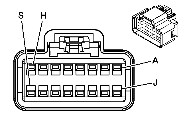
|
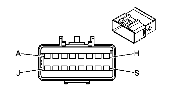
| ||||||||||||||
|---|---|---|---|---|---|---|---|---|---|---|---|---|---|---|---|
Connector Part Information |
| Connector Part Information |
| ||||||||||||
Pin | Wire Color | Circuit No. | Function | Pin | Wire Color | Circuit No. | Function | ||||||||
A | WHT | 1959 | Left Rear Midrange Speaker Output (-) (UK6) | A | WHT | 1959 | Left Rear Midrange Speaker Output (-) | ||||||||
B | TAN | 1859 | Left Rear Midrange Speaker Output (+) (UK6) | B | TAN | 1859 | Left Rear Midrange Speaker Output (+) | ||||||||
C | ORN | 1955 | Right Rear Midrange Speaker Output (-) (UK6) | C | ORN | 1955 | Right Rear Midrange Speaker Output (-) | ||||||||
D | TAN | 1855 | Right Rear Midrange Speaker Output (+) (UK6) | D | TAN | 1855 | Right Rear Midrange Speaker Output (+) | ||||||||
E | PPL | 493 | Rear Seat Audio Enable Signal (UK6) | E | PPL | 493 | Rear Seat Audio Enable Signal (UK6) | ||||||||
F | LT GRN | 1011 | Remote Radio Control Signal (UK6) | F | LT GRN | 1011 | Remote Radio Control Signal (UK6) | ||||||||
G | PPL | 1375 | Remote Radio Control Supply Voltage (UK6) | G | PPL | 1375 | Remote Radio Control Supply Voltage (UK6) | ||||||||
H | BRN/WHT | 230 | Instrument Panel Lamps Dimming Control (UK6) | H | BRN/WHT | 230 | Instrument Panel Lamps Dimming Control (UK6) | ||||||||
J | BLK/WHT | 351 | Ground (UK6) | J | BLK/WHT | 351 | Ground (UK6) | ||||||||
K | WHT | 1959 | Left Rear Midrange Speaker Output (-) (UK6) | K | WHT | 1959 | Left Rear Midrange Speaker Output (-) (UK6) | ||||||||
L | TAN | 1859 | Left Rear Midrange Speaker Output (+) (UK6) | L | TAN | 1859 | Left Rear Midrange Speaker Output (+) (UK6) | ||||||||
M | ORN | 1955 | Right Rear Midrange Speaker Output (-) (UK6) | M | ORN | 1955 | Right Rear Midrange Speaker Output (-) (UK6) | ||||||||
N | TAN | 1855 | Right Rear Midrange Speaker Output (+) (UK6) | N | TAN | 1855 | Right Rear Midrange Speaker Output (+) (UK6) | ||||||||
P | -- | -- | Upfitter Usage | P | BLK | 450 | Ground | ||||||||
R | -- | -- | Upfitter Usage | R | DK BLU/WHT | 149 | Courtesy Lamp Supply Voltage | ||||||||
S | -- | -- | Upfitter Usage | S | BRN | 2209 | Rear Park Lamps Supply Voltage | ||||||||
-- |

| ||||||||||
|---|---|---|---|---|---|---|---|---|---|---|---|
Connector Part Information | Upfitter Supplied | Connector Part Information |
| ||||||||
Pin | Wire Color | Circuit No. | Function | Pin | Wire Color | Circuit No. | Function | ||||
A | -- | -- | Upfitter Usage | A | RED/BLK | 1042 | Battery Positive Voltage | ||||
B | -- | -- | Upfitter Usage | B | BRN | 541 | Ignition 3 Voltage | ||||
C | -- | -- | Upfitter Usage | C | BLK | 450 | Ground | ||||
D | -- | -- | Upfitter Usage | D | -- | -- | Not Used | ||||
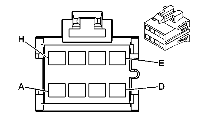
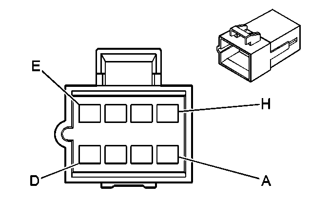
|
| ||||||||||||||
|---|---|---|---|---|---|---|---|---|---|---|---|---|---|---|---|
Connector Part Information |
| Connector Part Information |
| ||||||||||||
Pin | Wire Color | Circuit No. | Function | Pin | Wire Color | Circuit No. | Function | ||||||||
A | TAN | 1855 | Right Rear Midrange Speaker Output (+) | A | TAN | 1855 | Right Rear Midrange Speaker Output (+) | ||||||||
B | ORN | 1955 | Right Rear Midrange Speaker Output (-) | B | ORN | 1955 | Right Rear Midrange Speaker Output (-) | ||||||||
C | -- | -- | Not Used | C | -- | -- | Not Used | ||||||||
D | WHT | 194 | Door Unlock Control (AU3) | D | WHT | 194 | Door Unlock Control (AU3) | ||||||||
E | LT BLU | 195 | Door Lock Control (AU3) | E | LT BLU | 195 | Door Lock Control (AU3) | ||||||||
F | LT GRN | 1177 | Door Open Switch Signal | F | LT GRN | 1177 | Door Open Switch Signal | ||||||||
G | TAN/BLK | 1095 | Right Rear Door Lock Actuator Unlock Control (AU3) | G | TAN/BLK | 1095 | Right Rear Door Lock Actuator Unlock Control (AU3) | ||||||||
H | GRY | 295 | Door Lock Actuator Lock Control (AU3) | H | GRY | 295 | Door Lock Actuator Lock Control (AU3) | ||||||||
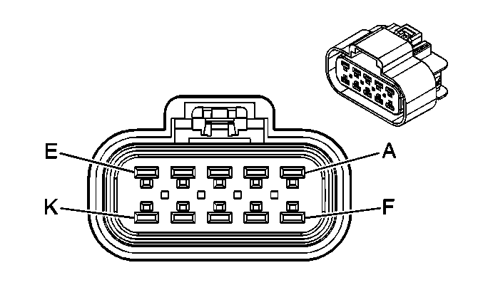
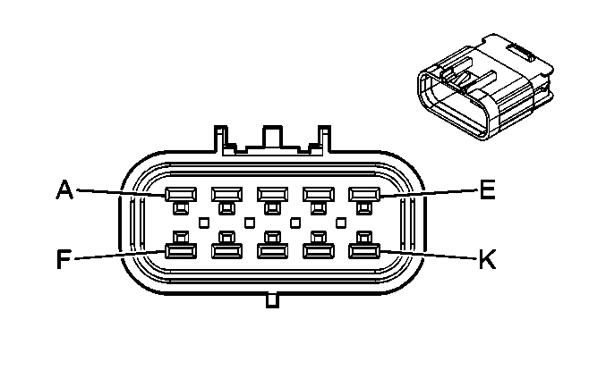
|
| ||||||||||||||
|---|---|---|---|---|---|---|---|---|---|---|---|---|---|---|---|
Connector Part Information |
| Connector Part Information |
| ||||||||||||
Pin | Wire Color | Circuit No. | Function | Pin | Wire Color | Circuit No. | Function | ||||||||
A | -- | -- | Upfitter Usage | A | YEL/BLK | 1334 | Left Rear Turn Signal Lamp Supply Voltage | ||||||||
B | -- | -- | Upfitter Usage | B | DK GRN/WHT | 1335 | Right Rear Turn Signal Lamp Supply Voltage | ||||||||
C | LT BLU | 1320 | Stop Lamp Supply Voltage - w/Cap Installed | C | WHT | 17 | Stop Lamp Switch Signal | ||||||||
-- | -- | Upfitter Usage - w/o Cap | |||||||||||||
D | -- | -- | Upfitter Usage | D | YEL | 618 | Left Rear Turn Signal Lamp Supply Voltage | ||||||||
E | -- | -- | Upfitter Usage | E | DK GRN | 619 | Right Rear Turn Signal Lamp Supply Voltage | ||||||||
F | -- | -- | Upfitter Usage | F | BRN | 2109 | Trailer Park Lamps Supply Voltage | ||||||||
G | BLK | 150 | Ground - w/Cap Installed | G | BLK | 150 | Ground | ||||||||
-- | -- | Upfitter Usage - w/o Cap | |||||||||||||
H | -- | -- | Upfitter Usage | H | LT GRN | 1624 | Trailer Backup Lamps Supply Voltage | ||||||||
J | -- | -- | Not Used | J | -- | -- | Not Used | ||||||||
K | -- | -- | Upfitter Usage | K | DK BLU/WHT | 149 | Courtesy Lamp Supply Voltage | ||||||||

|

| ||||||||||||||
|---|---|---|---|---|---|---|---|---|---|---|---|---|---|---|---|
Connector Part Information |
| Connector Part Information |
| ||||||||||||
Pin | Wire Color | Circuit No. | Function | Pin | Wire Color | Circuit No. | Function | ||||||||
A | GRY | 2599 | Auxiliary Mode Door Control (C69) | A | GRY | 2599 | Auxiliary Mode Door Control (C69) | ||||||||
B | DK BLU | 1926 | Auxiliary Blower Motor Low Control | B | DK BLU | 1926 | Auxiliary Blower Motor Low Control | ||||||||
C | WHT | 1924 | Auxiliary Blower Motor High Control | C | WHT | 1924 | Auxiliary Blower Motor High Control | ||||||||
D | ORN | 1925 | Auxiliary Blower Motor Medium Control | D | ORN | 1925 | Auxiliary Blower Motor Medium Control | ||||||||
E | BRN | 341 | Ignition 3 Voltage | E | BRN | 341 | Ignition 3 Voltage | ||||||||
F | ORN | 2775 | Auxiliary Air Temperature Door Control (C69) | F | ORN | 2775 | Auxiliary Air Temperature Door Control (C69) | ||||||||
-- |

| ||||||||||
|---|---|---|---|---|---|---|---|---|---|---|---|
Connector Part Information | Upfitter Supplied | Connector Part Information |
| ||||||||
Pin | Wire Color | Circuit No. | Function | Pin | Wire Color | Circuit No. | Function | ||||
A | -- | -- | Upfitter Usage | A | -- | -- | Not Used | ||||
B | -- | -- | Upfitter Usage | B | DK BLU | 1926 | Auxiliary Blower Motor Low Control | ||||
C | -- | -- | Upfitter Usage | C | WHT | 1924 | Auxiliary Blower Motor High Control | ||||
D | -- | -- | Upfitter Usage | D | ORN | 1925 | Auxiliary Blower Motor Medium Control | ||||
E | -- | -- | Upfitter Usage | E | BRN | 341 | Ignition 3 Voltage | ||||
F | -- | -- | Upfitter Usage | F | -- | -- | Not Used | ||||
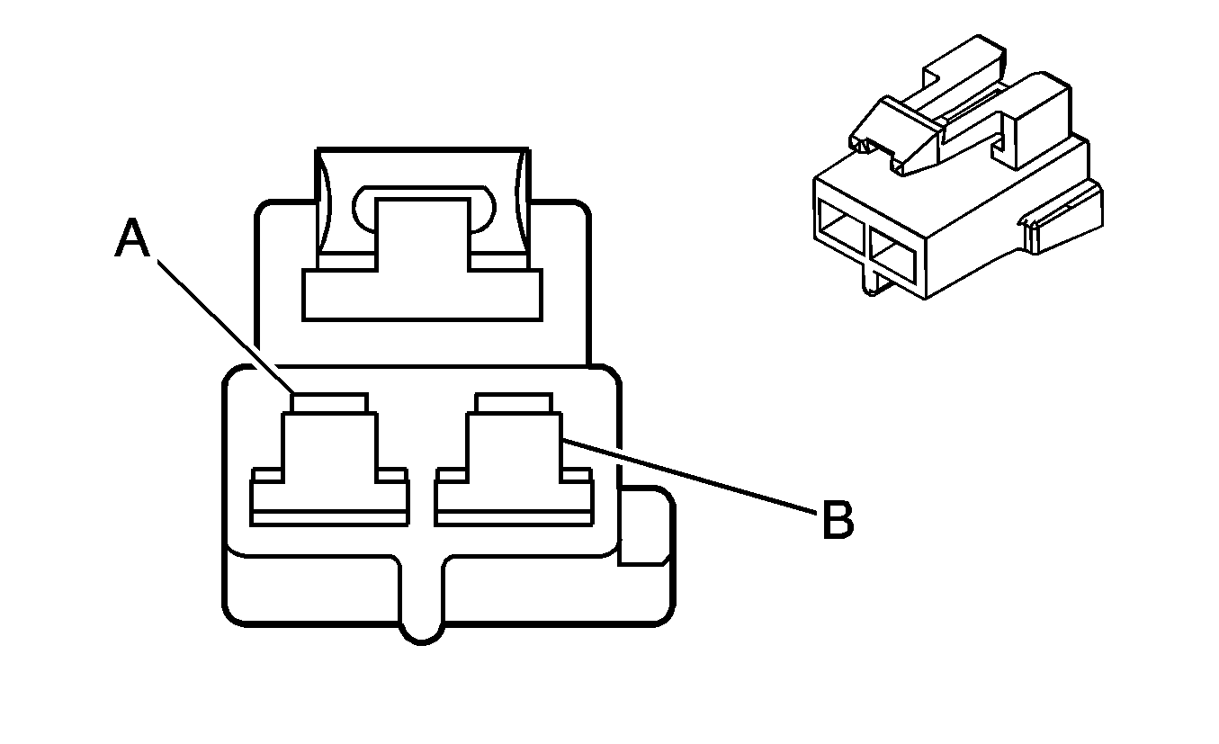
|
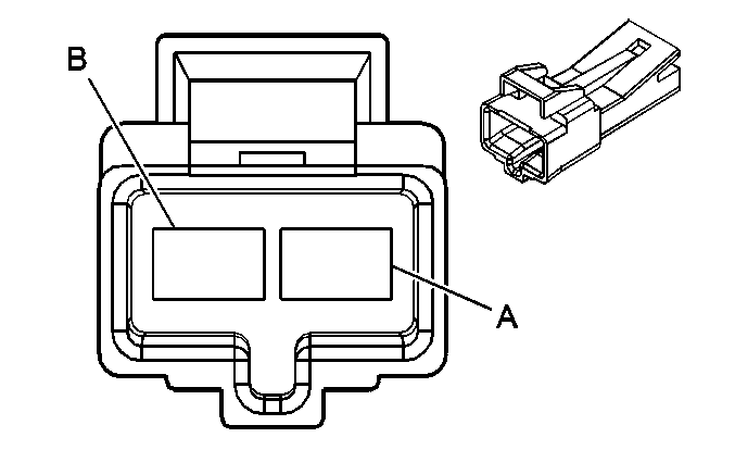
| ||||||||||||||
|---|---|---|---|---|---|---|---|---|---|---|---|---|---|---|---|
Connector Part Information |
| Connector Part Information |
| ||||||||||||
Pin | Wire Color | Circuit No. | Function | Pin | Wire Color | Circuit No. | Function | ||||||||
A | RED/WHT | 1740 | Battery Positive Voltage | A | RED/WHT | 1740 | Battery Positive Voltage | ||||||||
B | BLK | 850 | Ground | B | BLK | 850 | Ground | ||||||||
-- |

| ||||||||||
|---|---|---|---|---|---|---|---|---|---|---|---|
Connector Part Information | Upfitter Supplied | Connector Part Information |
| ||||||||
Pin | Wire Color | Circuit No. | Function | Pin | Wire Color | Circuit No. | Function | ||||
A | -- | -- | Upfitter Usage | A | RED/WHT | 1740 | Battery Positive Voltage | ||||
B | -- | -- | Upfitter Usage | B | BLK | 450 | Ground | ||||

|

| ||||||||||||||
|---|---|---|---|---|---|---|---|---|---|---|---|---|---|---|---|
Connector Part Information |
| Connector Part Information |
| ||||||||||||
Pin | Wire Color | Circuit No. | Function | Pin | Wire Color | Circuit No. | Function | ||||||||
A | TAN | 1859 | Left Rear Midrange Speaker Output (+) (UB1/UC6) | A | TAN | 1859 | Left Rear Midrange Speaker Output (+) | ||||||||
B | WHT | 1959 | Left Rear Midrange Speaker Output (-) (UB1/UC6) | B | WHT | 1959 | Left Rear Midrange Speaker Output (-) | ||||||||
C | -- | -- | Not Used | C | -- | -- | Not Used | ||||||||
D | PPL | 293 | Rear Defog Element Supply Voltage (C49) | D | PPL | 293 | Rear Defog Element Supply Voltage (C49) | ||||||||
E | BLK | 850 | Ground (C49) | E | BLK | 850 | Ground (C49) | ||||||||
F | -- | -- | Not Used | F | -- | -- | Not Used | ||||||||
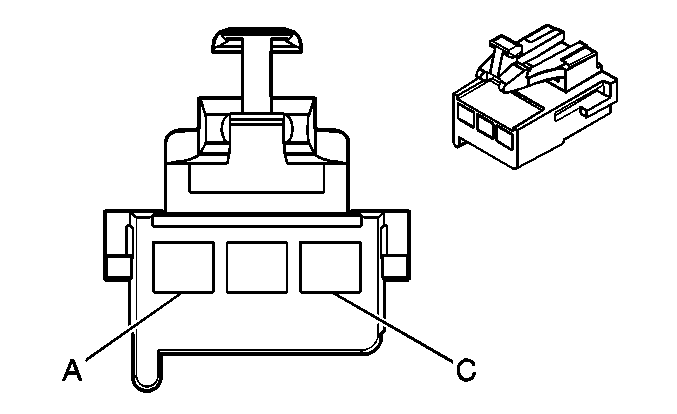
|
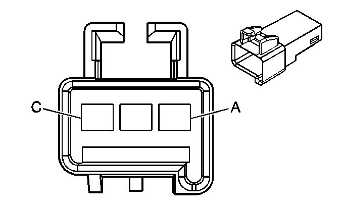
| ||||||||||||||
|---|---|---|---|---|---|---|---|---|---|---|---|---|---|---|---|
Connector Part Information |
| Connector Part Information |
| ||||||||||||
Pin | Wire Color | Circuit No. | Function | Pin | Wire Color | Circuit No. | Function | ||||||||
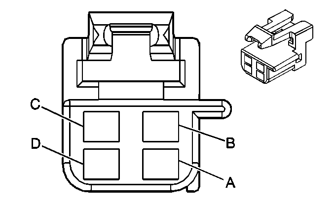
A | PPL | 293 | Rear Defog Element Supply Voltage (C49) | A | PPL | 293 | Rear Defog Element Supply Voltage (C49) | ||||||||
B | BLK | 1050 | Ground | B | BLK | 1050 | Ground | ||||||||
C | BRN | 2509 | Left Rear Park Lamps Supply Voltage | C | BRN | 2509 | Left Rear Park Lamps Supply Voltage | ||||||||
|

| ||||||||||||||
|---|---|---|---|---|---|---|---|---|---|---|---|---|---|---|---|
Connector Part Information |
| Connector Part Information |
| ||||||||||||
Pin | Wire Color | Circuit No. | Function | Pin | Wire Color | Circuit No. | Function | ||||||||
A | WHT | 1959 | Left Rear Midrange Speaker Output (-) | A | WHT | 1959 | Left Rear Midrange Speaker Output (-) | ||||||||
B | TAN | 1859 | Left Rear Midrange Speaker Output (+) | B | TAN | 1859 | Left Rear Midrange Speaker Output (+) | ||||||||
C | ORN | 1955 | Right Rear Midrange Speaker Output (-) | C | ORN | 1955 | Right Rear Midrange Speaker Output (-) | ||||||||
D | TAN | 1855 | Right Rear Midrange Speaker Output (+) | D | TAN | 1855 | Right Rear Midrange Speaker Output (+) | ||||||||

|

| ||||||||||||||
|---|---|---|---|---|---|---|---|---|---|---|---|---|---|---|---|
Connector Part Information |
| Connector Part Information |
| ||||||||||||
Pin | Wire Color | Circuit No. | Function | Pin | Wire Color | Circuit No. | Function | ||||||||
A | DK BLU/WHT | 149 | Courtesy Lamp Supply Voltage | A | DK BLU/WHT | 149 | Courtesy Lamp Supply Voltage | ||||||||
B | BLK | 850 | Ground | B | BLK | 850 | Ground | ||||||||

|

| ||||||||||||||
|---|---|---|---|---|---|---|---|---|---|---|---|---|---|---|---|
Connector Part Information |
| Connector Part Information |
| ||||||||||||
Pin | Wire Color | Circuit No. | Function | Pin | Wire Color | Circuit No. | Function | ||||||||
A | LT BLU | 1320 | CHMSL Supply Voltage | A | LT BLU | 1320 | CHMSL Supply Voltage | ||||||||
B | BLK | 850 | Ground | B | BLK | 850 | Ground | ||||||||
|
| ||||||||||||||
|---|---|---|---|---|---|---|---|---|---|---|---|---|---|---|---|
Connector Part Information |
| Connector Part Information |
| ||||||||||||
Pin | Wire Color | Circuit No. | Function | Pin | Wire Color | Circuit No. | Function | ||||||||
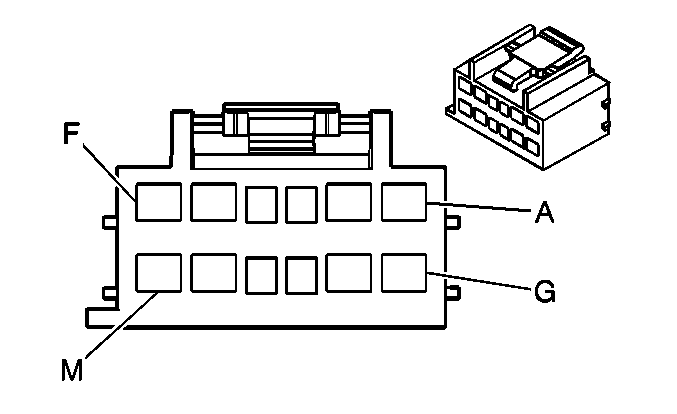
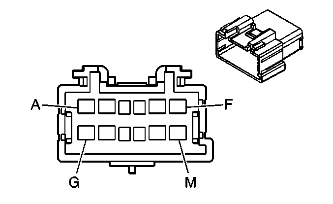
A | ORN | 1925 | Auxiliary Blower Motor Medium Speed Control | A | ORN | 1925 | Auxiliary Blower Motor Medium Speed Control | ||||||||
B | DK BLU | 1926 | Auxiliary Blower Motor Low Speed Control | B | DK BLU | 1926 | Auxiliary Blower Motor Low Speed Control | ||||||||
C | DK BLU/WHT | 149 | Courtesy Lamp Supply Voltage | C | DK BLU/WHT | 149 | Courtesy Lamp Supply Voltage | ||||||||
D | DK BLU/WHT | 149 | Courtesy Lamp Supply Voltage | D | DK BLU/WHT | 149 | Courtesy Lamp Supply Voltage | ||||||||
E | ORN | 1732 | Inadvertent Power Supply Voltage | E | ORN | 1732 | Inadvertent Power Supply Voltage | ||||||||
F | BRN | 341 | Ignition 3 Voltage | F | BRN | 341 | Ignition 3 Voltage | ||||||||
G | BRN/WHT | 230 | Instrument Panel Lamps Dimming Control | G | BRN/WHT | 230 | Instrument Panel Lamps Dimming Control | ||||||||
H | WHT | 1924 | Auxiliary Blower Motor High Speed Control | H | WHT | 1924 | Auxiliary Blower Motor High Speed Control | ||||||||
J | PPL/WHT | 5264 | Rear Auxiliary Mode Door Control | J | PPL/WHT | 5264 | Rear Auxiliary Mode Door Control | ||||||||
K | BRN | 5263 | Rear Auxiliary Air Temperature Door Control | K | BRN | 5263 | Rear Auxiliary Air Temperature Door Control | ||||||||
L | PNK/BLK | 5265 | Rear Auxiliary Blower Motor Switch Control | L | PNK/BLK | 5265 | Rear Auxiliary Blower Motor Switch Control | ||||||||
M | BLK | 450 | Ground | M | BLK | 450 | Ground | ||||||||
