Electronic Brake Control Module Replacement w/JL4
Removal Procedure
Important: After installation, calibrate the new electronic brake control module (EBCM) to the tire size that is appropriate to the vehicle.
- Disconnect the negative battery cable. Refer to Battery Negative Cable Disconnection and Connection .
- Raise and suitably support the vehicle. Refer to Lifting and Jacking the Vehicle .
- Thoroughly wash all contaminants from around the EHCU.
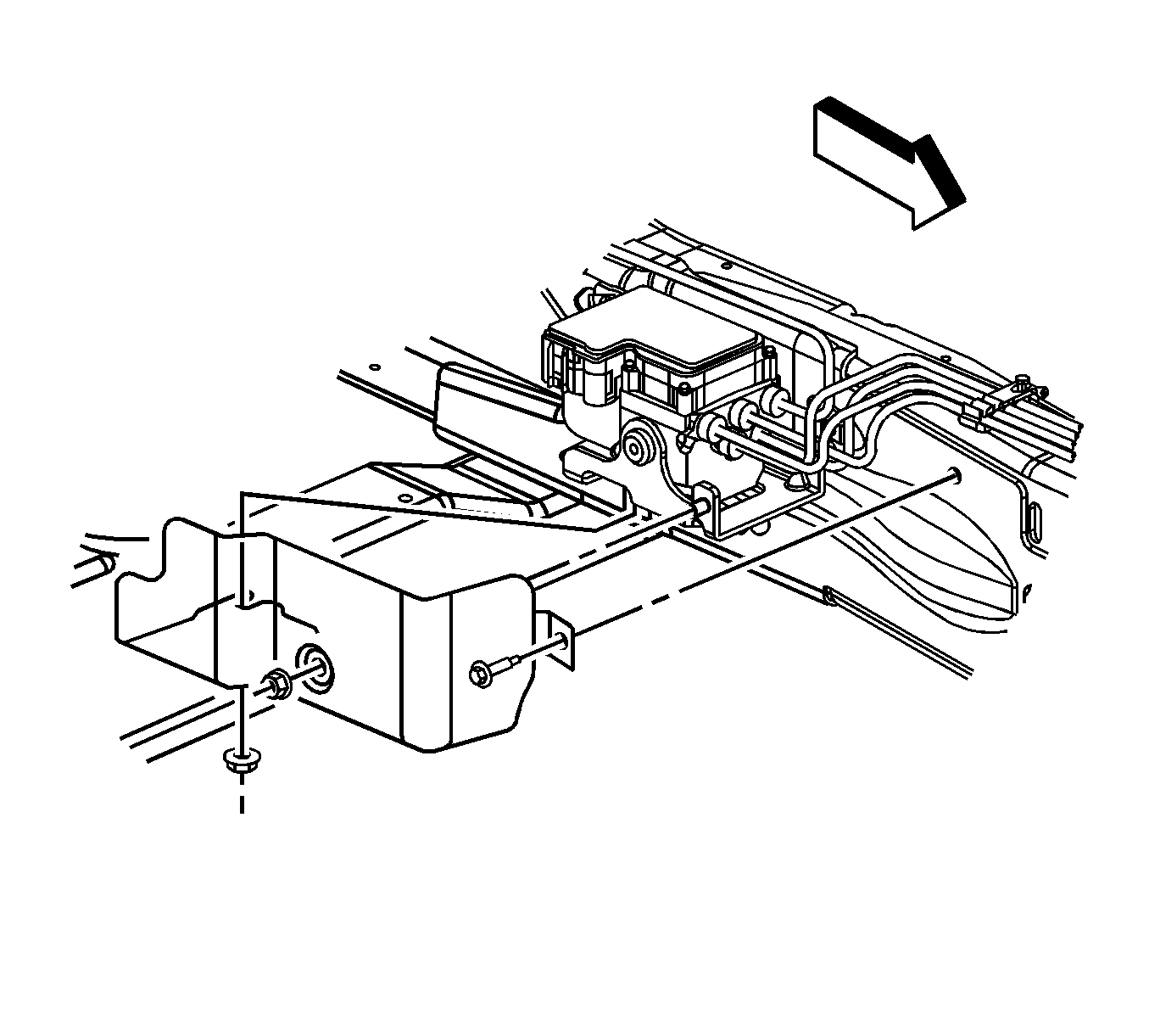
- For cutaway vehicles, remove the splash shield.
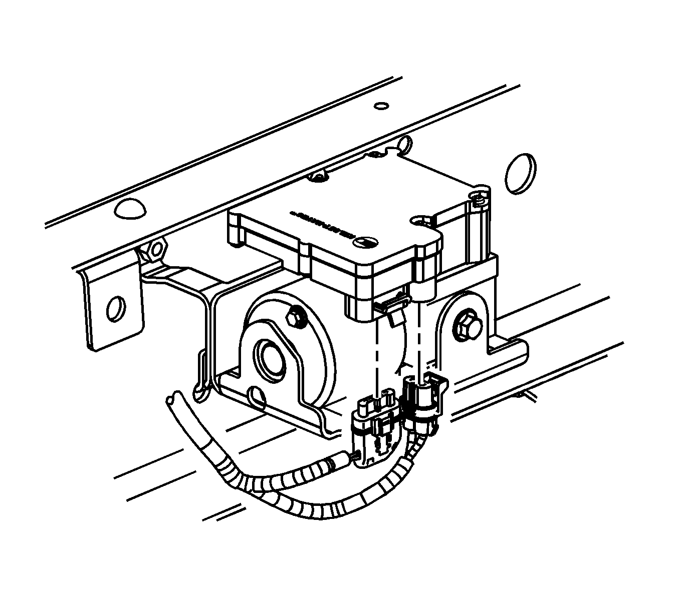
- Disconnect the electrical connectors from the EBCM.
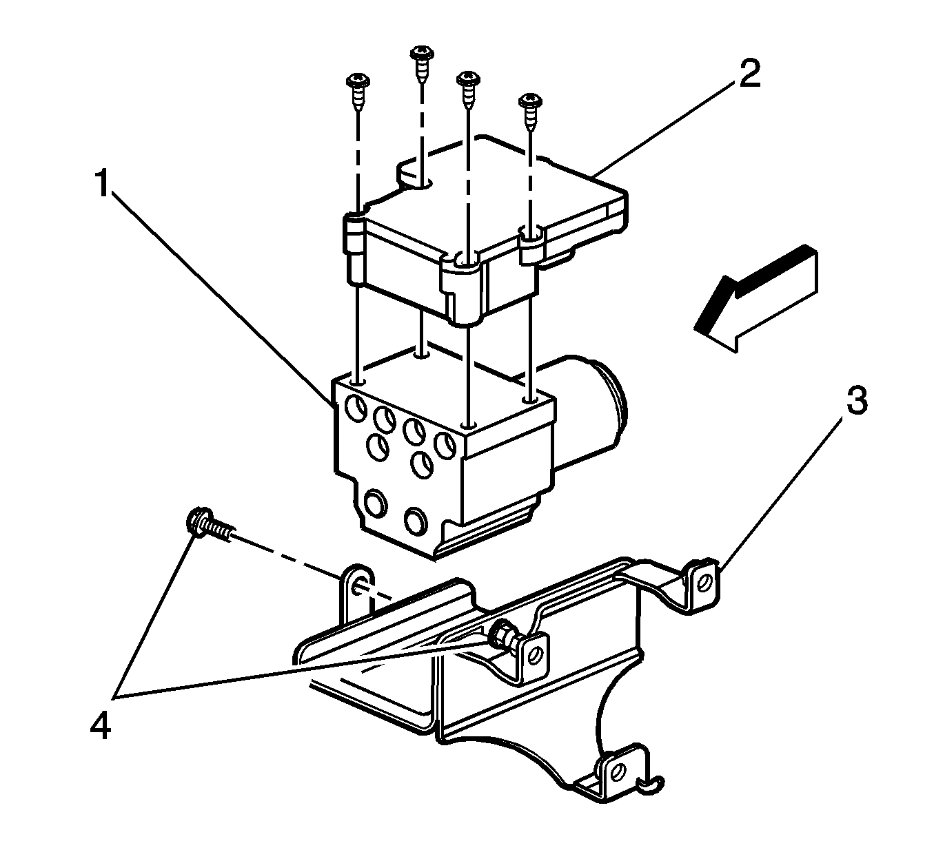
- Remove the mounting screws that fasten the EBCM (2) to the brake pressure modulator valve (BPMV) (1).
- Remove the EBCM (2) from the BPMV (1). Removal may require a light amount of force.
- Clean the BPMV to EBCM mounting surfaces with a clean cloth.

Important: The area around the electric hydraulic control unit (EHCU) MUST be free from loose dirt to prevent contamination of disassembled ABS components.


Installation Procedure
- Install the EBCM (2) on to the BPMV (1).
- Install the screws to the EBCM (2).
- Connect the electrical connectors to the EBCM.
- For cutaway vehicles, install the splash shield.
- Lower the vehicle.
- Connect the negative battery cable. Refer to Battery Negative Cable Disconnection and Connection .
- Revise the tire calibration using the Tire Size Calibration function.
- Verify correct system operation. Refer to Diagnostic Starting Point - Antilock Brake System .
- Refer to Control Module References for programming and setup information.

Important: Do not use room temperature vulcanizing (RTV) or any other type of sealant on the EBCM gasket or mating surfaces.
Notice: Refer to Fastener Notice in the Preface section.
Tighten
Tighten the screws to 5 N·m (44 lb in) in an X-pattern.


Tighten
Tighten the splash shield bolts to 25 N·m (18 lb ft).
Electronic Brake Control Module Replacement w/o JL4
Removal Procedure
Important: After installation, calibrate the new electronic brake control module (EBCM) to the tire size that is appropriate to the vehicle.
- Disconnect the negative battery cable. Refer to Battery Negative Cable Disconnection and Connection .
- Raise and suitably support the vehicle. Refer to Lifting and Jacking the Vehicle .
- Thoroughly wash all contaminants from around the EHCU.
- For cutaway vehicles, remove the splash shield.
- Disconnect the electrical connectors from the EBCM.
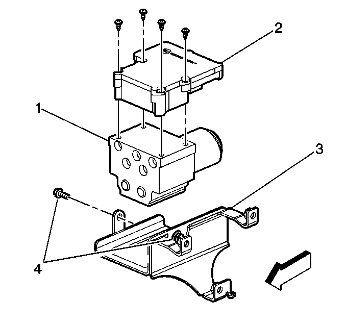
- Remove the mounting screws that fasten the EBCM (2) to the brake pressure modulator valve (BPMV) (1).
- Remove the EBCM (2) from the BPMV (1). Removal may require a light amount of force.
- Clean the BPMV to EBCM mounting surfaces with a clean cloth.

Important: The area around the electric hydraulic control unit (EHCU) MUST be free from loose dirt to prevent contamination of disassembled ABS components.


Installation Procedure
- Install the EBCM (2) on to the BPMV (1).
- Install the screws to the EBCM (2).
- Connect the electrical connectors to the EBCM.
- For cutaway vehicles, install the splash shield.
- Lower the vehicle.
- Connect the negative battery cable. Refer to Battery Negative Cable Disconnection and Connection .
- Revise the tire calibration using the Tire Size Calibration function.
- Verify correct system operation. Refer to Diagnostic Starting Point - Antilock Brake System .
- Refer to Control Module References for programming and setup information.

Important: Do not use RTV or any other type of sealant on the EBCM gasket or mating surfaces.
Notice: Refer to Fastener Notice in the Preface section.
Tighten
Tighten the screws to 5 N·m (44 lb in) in an X-pattern.


Tighten
Tighten the splash shield bolts to 25 N·m (18 lb ft).
