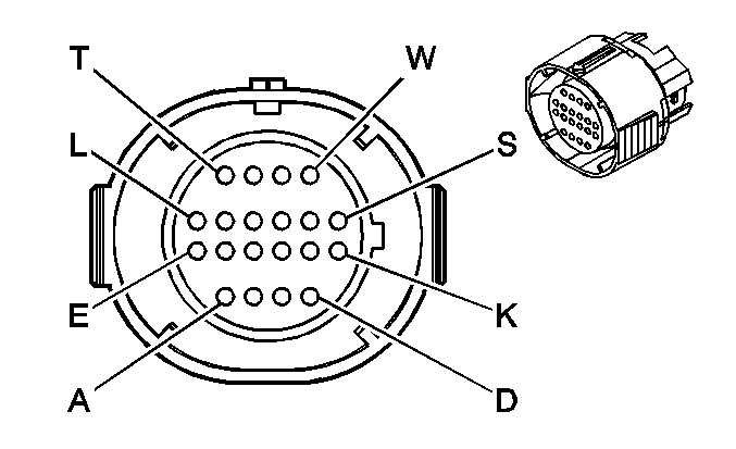
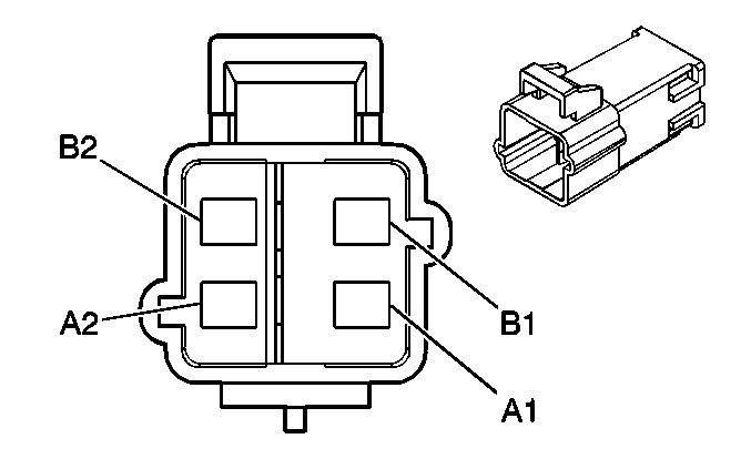
|
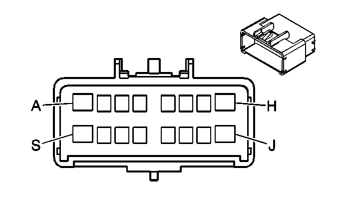
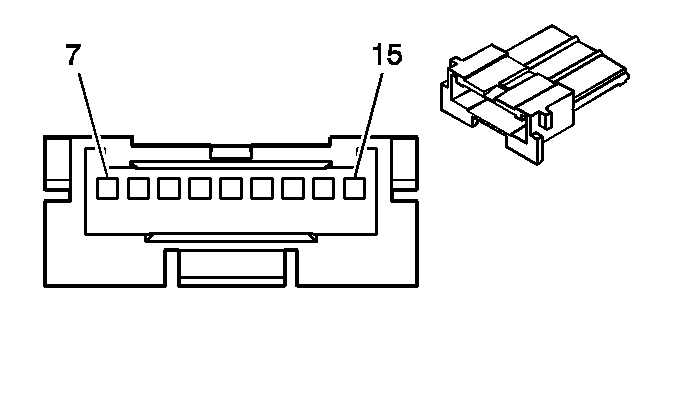
| ||||||||||||||
|---|---|---|---|---|---|---|---|---|---|---|---|---|---|---|---|
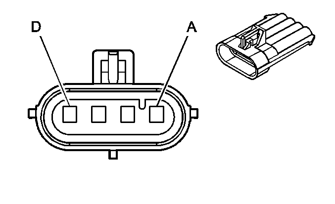
Connector Part Information |
| Connector Part Information |
| ||||||||||||
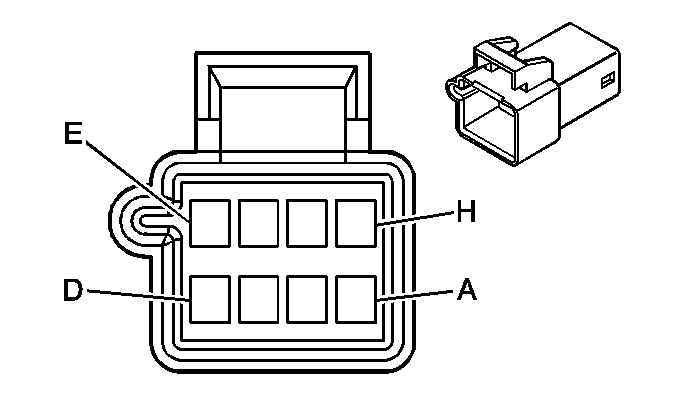
Pin | Wire Color | Circuit No. | Function | Pin | Wire Color | Circuit No. | Function | ||||||||
A | WHT | 85 | Cruise Control Engaged Signal | A | WHT | 85 | Cruise Control Engaged Signal | ||||||||
B | PNK | 239 | Ignition 1 Voltage | B | PNK | 239 | Ignition 1 Voltage | ||||||||
C | PPL | 420 | TCC Brake Switch Signal | C | PPL | 420 | TCC Brake Switch Signal | ||||||||
D | PPL | 1500 | Ignition 0 Voltage | D | PPL | 1500 | Ignition 0 Voltage | ||||||||
E | WHT | 17 | Stop Lamp Switch Signal | E | WHT | 17 | Stop Lamp Switch Signal | ||||||||
F | DK GRN | 83 | Cruise Control Inhibit Signal | F | DK GRN | 83 | Cruise Control Inhibit Signal | ||||||||
G | DK GRN | 389 | Vehicle Speed Signal | G | DK GRN | 389 | Vehicle Speed Signal | ||||||||
H | BLK | 808 | Low Reference | H | BLK | 808 | Low Reference | ||||||||
J | DK GRN | 890 | Fuel Tank Pressure Sensor Signal | J | DK GRN | 890 | Fuel Tank Pressure Sensor Signal | ||||||||
K | GRY | 2709 | 5 Volt Reference | K | GRY | 2709 | 5 Volt Reference | ||||||||
L | BLK | 884 | Left Rear Wheel Speed Sensor Signal | L | BLK | 884 | Left Rear Wheel Speed Sensor Signal | ||||||||
M | RED | 885 | Left Rear Wheel Speed Sensor Low Reference | M | RED | 885 | Left Rear Wheel Speed Sensor Low Reference | ||||||||
N | BRN | 882 | Right Rear Wheel Speed Sensor Signal | N | BRN | 882 | Right Rear Wheel Speed Sensor Signal | ||||||||
P | WHT | 883 | Right Rear Wheel Speed Sensor Low Reference | P | WHT | 883 | Right Rear Wheel Speed Sensor Low Reference | ||||||||
R | LT BLU | 1122 | ABS/TCS Class 2 Serial Data | R | LT BLU | 1122 | ABS/TCS Class 2 Serial Data | ||||||||
S | DK GRN | 1049 | PCM Class 2 Serial Data | S | DK GRN | 1049 | PCM Class 2 Serial Data | ||||||||
T | BLK/WHT | 451 | Ground | T | BLK/WHT | 451 | Ground | ||||||||
U | PPL | 806 | Crank Voltage | U | PPL | 806 | Crank Voltage | ||||||||
V | BRN/WHT | 419 | MIL Control | V | BRN/WHT | 419 | MIL Control | ||||||||
W | PPL | 1589 | Fuel Level Sensor Signal | W | PPL | 1589 | Fuel Level Sensor Signal | ||||||||
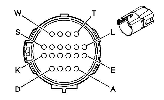
|
|
| ||||||||||||||
|---|---|---|---|---|---|---|---|---|---|---|---|---|---|---|---|
Connector Part Information |
| Connector Part Information |
| ||||||||||||
Pin | Wire Color | Circuit No. | Function | Pin | Wire Color | Circuit No. | Function | ||||||||
A | WHT | 85 | Cruise Control Engaged Signal | A | WHT | 85 | Cruise Control Engaged Signal | ||||||||
B | PNK | 239 | Ignition 1 Voltage | B | PNK | 239 | Ignition 1 Voltage | ||||||||
C | PPL | 420 | TCC Brake Switch Signal | C | PPL | 420 | TCC Brake Switch Signal | ||||||||
D | PPL | 1500 | Ignition 0 Voltage | D | PPL | 1500 | Ignition 0 Voltage | ||||||||
E | WHT | 17 | Stop Lamp Switch Signal (w/ JL9) | E | WHT | 17 | Stop Lamp Switch Signal | ||||||||
F | DK GRN | 83 | Cruise Control Inhibit Signal | F | DK GRN | 83 | Cruise Control Inhibit Signal | ||||||||
G | DK GRN | 389 | Vehicle Speed Signal | G | DK GRN | 389 | Vehicle Speed Signal | ||||||||
H | BLK | 808 | Low Reference | H | BLK | 808 | Low Reference | ||||||||
J | DK GRN | 890 | Fuel Tank Pressure Sensor Signal | DK GRN | 890 | Fuel Tank Pressure Sensor Signal | |||||||||
K | GRY | 2709 | 5 Volt Reference | K | GRY | 2709 | 5 Volt Reference | ||||||||
L | BLK | 884 | Left Rear Wheel Speed Sensor Signal (w/ JL9) | L | BLK | 884 | Left Rear Wheel Speed Sensor Signal | ||||||||
M | RED | 885 | Left Rear Wheel Speed Sensor Low Reference (w/ JL9) | M | RED | 885 | Left Rear Wheel Speed Sensor Low Reference | ||||||||
N | BRN | 882 | Right Rear Wheel Speed Sensor Signal (w/ JL9) | N | BRN | 882 | Right Rear Wheel Speed Sensor Signal | ||||||||
P | WHT | 883 | Right Rear Wheel Speed Sensor Low Reference (w/ JL9) | P | WHT | 883 | Right Rear Wheel Speed Sensor Low Reference | ||||||||
R | LT BLU | 1122 | ABS/TCS Class 2 Serial Data (w/ JL9) | R | LT BLU | 1122 | ABS/TCS Class 2 Serial Data | ||||||||
S | DK GRN | 1049 | PCM Class 2 Serial Data | S | DK GRN | 1049 | PCM Class 2 Serial Data | ||||||||
T | BLK/WHT | 451 | Ground | T | BLK/WHT | 451 | Ground | ||||||||
U | PPL | 806 | Crank Voltage | U | PPL | 806 | Crank Voltage | ||||||||
V | BRN/WHT | 419 | MIL Control | V | BRN/WHT | 419 | MIL Control | ||||||||
W | PPL | 1589 | Fuel Level Sensor Signal | W | PPL | 1589 | Fuel Level Sensor Signal | ||||||||
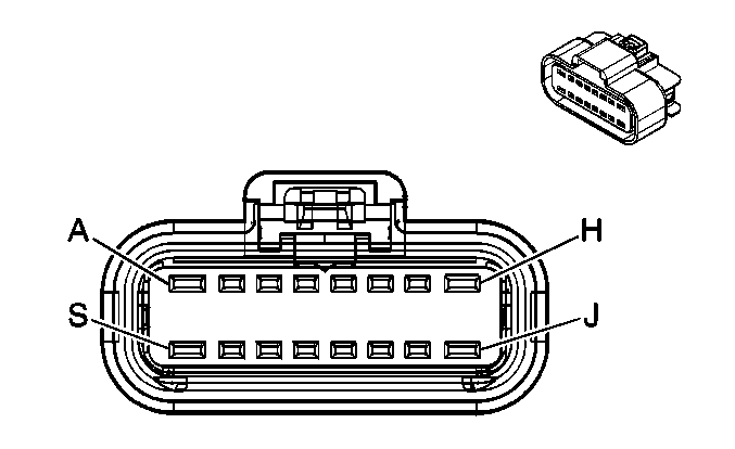
|
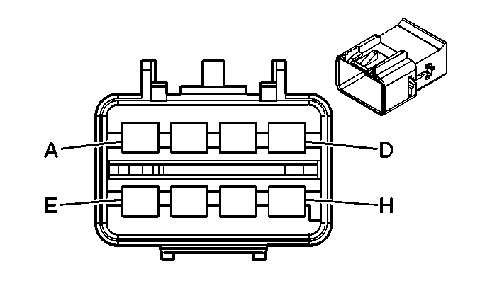
| ||||||||||||||
|---|---|---|---|---|---|---|---|---|---|---|---|---|---|---|---|
Connector Part Information |
| Connector Part Information |
| ||||||||||||
Pin | Wire Color | Circuit No. | Function | Pin | Wire Color | Circuit No. | Function | ||||||||
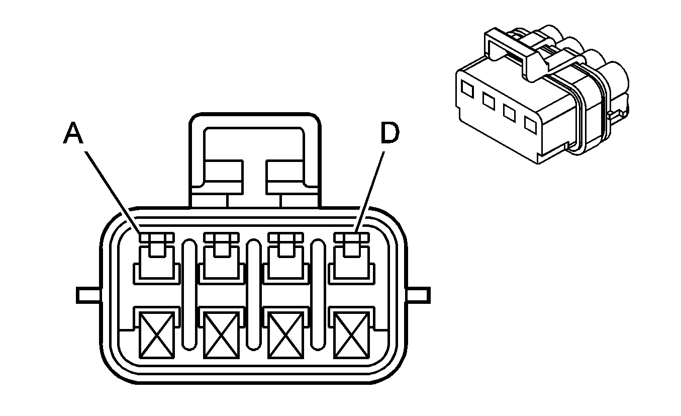
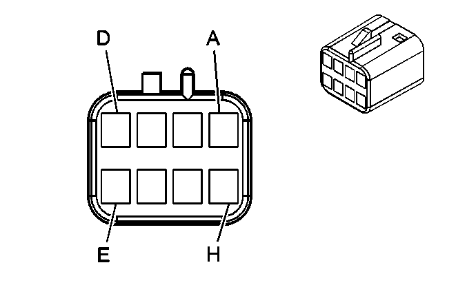
A | PNK | 639 | Ignition 1 Voltage | A | PNK | 639 | Ignition 1 Voltage | ||||||||
B | YEL | 410 | ECT Sensor Signal | B | YEL | 410 | ECT Sensor Signal | ||||||||
C | BLK | 1744 | Fuel Injector 1 Control | C | BLK | 1744 | Fuel Injector 1 Control | ||||||||
D | LT GRN/BLK | 1745 | Fuel Injector 2 Control | D | LT GRN/BLK | 1745 | Fuel Injector 2 Control | ||||||||
E | PNK/BLK | 1746 | Fuel Injection 3 Control | E | PNK/BLK | 1746 | Fuel Injection 3 Control | ||||||||
F | LT BLU/BLK | 844 | Fuel Injection 4 Control | F | LT BLU/BLK |
844 | Fuel Injection 4 Control | ||||||||
G | BLK/WHT | 845 | Fuel Injection 5 Control | G | BLK/WHT | 845 | Fuel Injection 5 Control | ||||||||
H | YEL/BLK | 846 | Fuel Injection 6 Control | H | YEL/BLK | 846 | Fuel Injection 6 Control | ||||||||
J | -- | -- | Not Used | J | -- | -- | Not Used | ||||||||
K | GRY | 2704 | 5 Volt Reference | K | GRY | 2704 | 5 Volt Reference | ||||||||
L | ORN/BLK | 469 | Low Reference | L | ORN/BLK | 469 | Low Reference | ||||||||
M | LT GRN | 432 | MAP Sensor Signal | M | LT GRN | 432 | MAP Sensor Signal | ||||||||
N | RED | 631 | 12 Volt Reference | N | RED/WHT | 812 | 12 Volt Reference | ||||||||
P | PNK/BLK | 632 | Low Reference | P | BLK | 407 | Low Reference | ||||||||
R | BRN/WHT | 633 | CMP Sensor Signal | R | BRN/WHT | 633 | CMP Sensor Signal | ||||||||
S | -- | -- | Not Used | S | -- | -- | Not Used | ||||||||
|
| ||||||||||||||
|---|---|---|---|---|---|---|---|---|---|---|---|---|---|---|---|
Connector Part Information |
| Connector Part Information |
| ||||||||||||
Pin | Wire Color | Circuit No. | Function | Pin | Wire Color | Circuit No. | Function | ||||||||
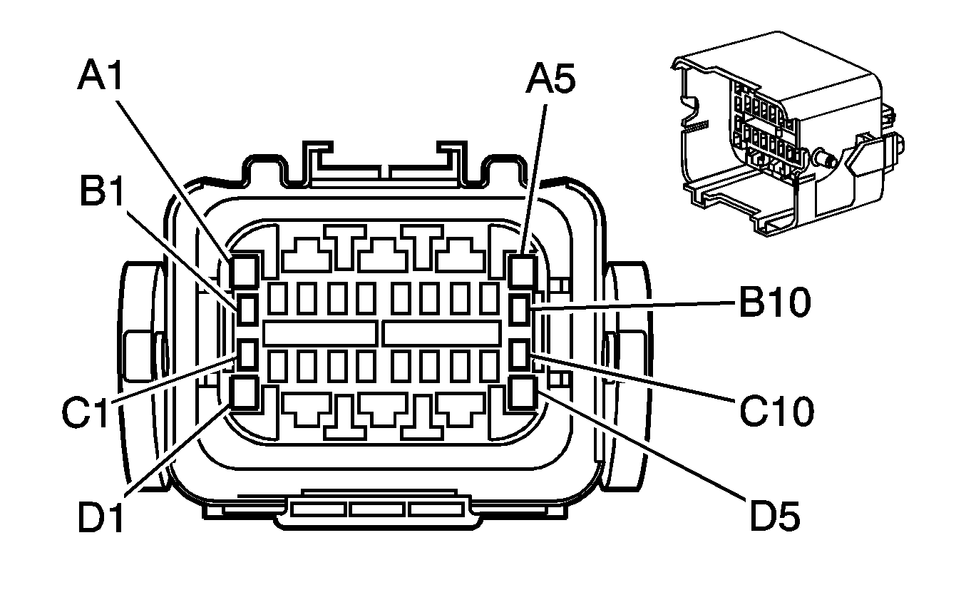
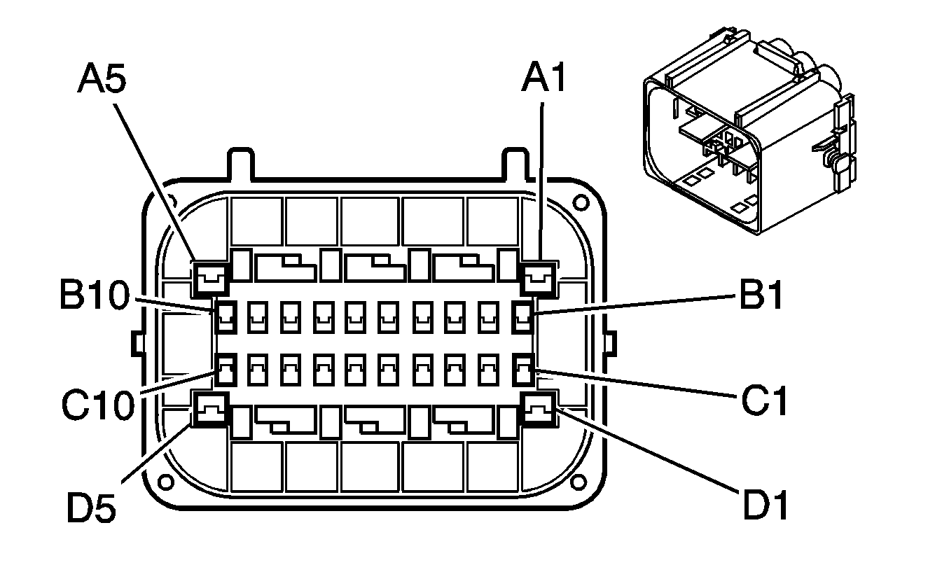
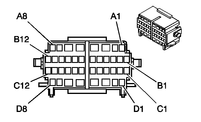
A1 | PNK | 1200 | Headlamp High Beam Signal | A1 | PNK | 1200 | Headlamp High Beam Signal | ||||||||
A2 | RED | 42 | Battery Positive Voltage | A2 | RED | 42 | Battery Positive Voltage | ||||||||
A3 | RED | 242 | Battery Positive Voltage | A3 | RED | 242 | Battery Positive Voltage | ||||||||
A4 | RED | 342 | Battery Positive Voltage | A4 | RED | 342 | Battery Positive Voltage | ||||||||
A5 | BLK | 28 | Horn Relay Control | A5 | BLK | 28 | Horn Relay Control | ||||||||
B1 | LT GRN/BLK | 592 | DRL Relay Control | B1 | LT GRN/BLK | 592 | DRL Relay Control | ||||||||
B2 | YEL | 32 | Instrument Panel Lamp Fuse Supply Voltage - 1 | B2 | YEL | 32 | Instrument Panel Lamp Fuse Supply Voltage - 1 | ||||||||
B3 | DK BLU | 1201 | Headlamp Low Beam Signal | B3 | DK BLU | 1201 | Headlamp Low Beam Signal | ||||||||
B4 | GRY | 349 | Discriminating Sensor - Left - Signal | B4 | GRY | 349 | Discriminating Sensor - Left - Signal | ||||||||
B5 | YEL | 354 | Discriminating Sensor - Signal | B5 | YEL | 354 | Discriminating Sensor - Signal | ||||||||
B6 | YEL/BLK | 68 | Low Coolant Level Indicator Control | B6 | YEL/BLK | 68 | Low Coolant Level Indicator Control | ||||||||
B7 | BLK | 2710 | Battery Positive Voltage (w/ 9C1/9C3/9C6) | B7 | BLK | 2710 | Battery Positive Voltage (w/ 9C1/9C3/9C6) | ||||||||
B8 | BLK/WHT | 2711 | Battery Positive Voltage (w/ 9C1/9C3/9C6) | B8 | BLK/WHT | 2711 | Battery Positive Voltage (w/ 9C1/9C3/9C6) | ||||||||
B8 | DK GRN/ WHT | 1317 | Fog Lamp Relay Control (w/ T96) | B8 | DK GRN/ WHT | 1317 | Fog Lamp Relay Control (w/ T96) | ||||||||
B9 | PNK | 239 | Ignition 1 Voltage | B9 | PNK | 239 | Ignition 1 Voltage | ||||||||
B10 | LT BLU | 14 | Left Turn Signal Lamps Supply Voltage | B10 | LT BLU | 14 | Left Turn Signal Lamps Supply Voltage (Impala) | ||||||||
B10 | YEL | 685 | Left Turn Signal Lamps Supply Voltage (Monte Carlo) | ||||||||||||
C1 | RED | 228 | Windshield Washer Pump Control | C1 | RED | 228 | Windshield Washer Pump Control | ||||||||
C2 | -- | -- | Not Used | C2 | -- | -- | Not Used | ||||||||
C3 | BLK/WHT | 99 | Windshield Washer Fluid Level Signal | C3 | BLK/WHT | 99 | Windshield Washer Fluid Level Signal | ||||||||
C4 | LT GRN/BLK | 735 | Ambient Air Temperature Sensor Signal (w/o 9C1/9C3/9C6) | C4 | LT GRN/BLK | 735 | Ambient Air Temperature Sensor Signal (w/o 9C1/9C3/9C6) | ||||||||
C5 | WHT | 1310 | EVAP Canister Vent Solenoid Control | C5 | WHT | 1310 | EVAP Canister Vent Solenoid Control | ||||||||
C6 | PNK | 2322 | Emergency Vehicle Rear Lamps Supply Voltage (w/ 9C1/9C3/9C6) | C6 | PNK | 2322 | Emergency Vehicle Rear Lamps Supply Voltage (w/ 9C1/9C3/9C6) | ||||||||
C7 | -- | -- | Not Used | C7 | -- | -- | Not Used | ||||||||
C8 | BLK/WHT | 1251 | Ground | C8 | BLK/WHT | 1251 | Ground | ||||||||
C9 | -- | -- | Not Used | C9 | -- | -- | Not Used | ||||||||
C10 | DK BLU | 15 | Right Turn Signal Lamps Supply Voltage | C10 | DK BLU | 15 | Right Turn Signal Lamps Supply Voltage (Impala) | ||||||||
C10 | TAN | 686 | Right Turn Signal Lamps Supply Voltage (Monte Carlo) | ||||||||||||
D1 | GRY | 120 | Fuel Pump Supply Voltage | D1 | GRY | 120 | Fuel Pump Supply Voltage | ||||||||
D2 | RED | 742 | Battery Positive Voltage | D2 | RED | 742 | Battery Positive Voltage | ||||||||
D3 | RED | 1042 | Battery Positive Voltage | D3 | RED | 1042 | Battery Positive Voltage | ||||||||
D4 | -- | -- | Not Used | D4 | -- | -- | Not Used | ||||||||
D5 | PPL | 34 | Front Fog Lamps Supply Voltage (w/ T96) | D5 | PPL | 34 | Front Fog Lamps Supply Voltage (w/o 9C1/9C3/9C6) | ||||||||
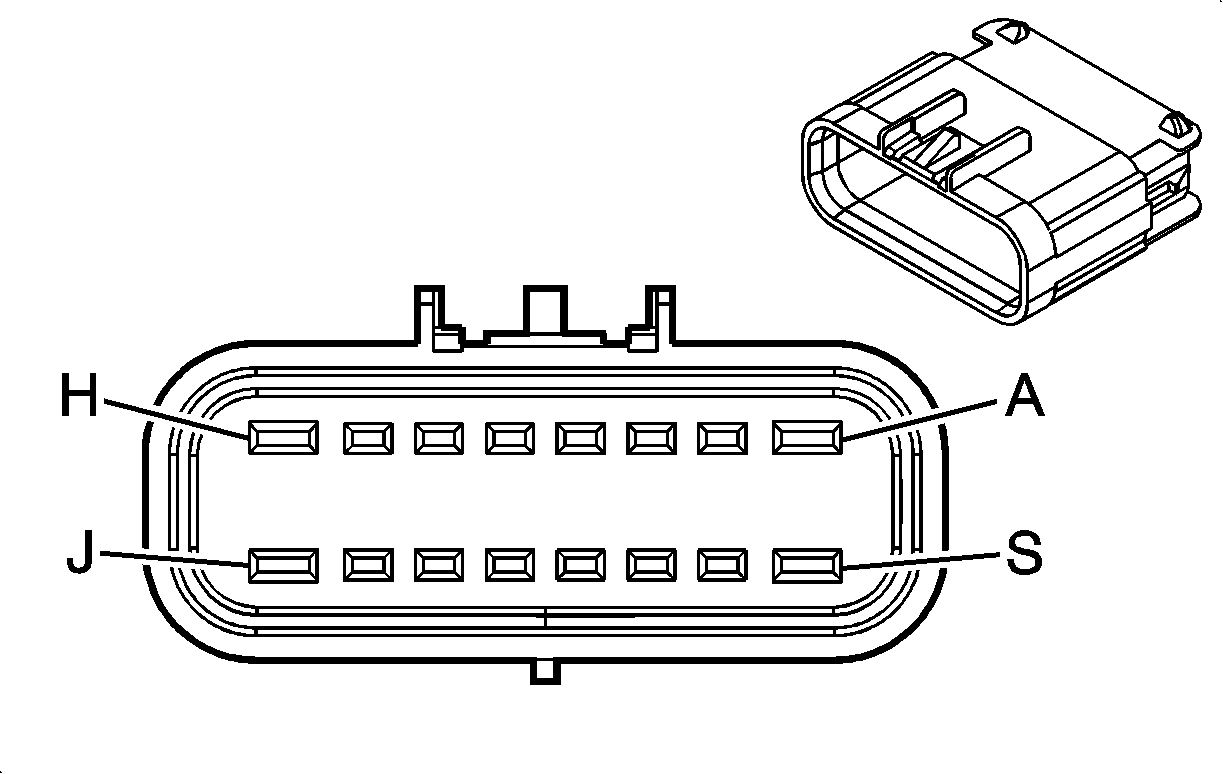
|
| ||||||||||||||
|---|---|---|---|---|---|---|---|---|---|---|---|---|---|---|---|
Connector Part Information |
| Connector Part Information |
| ||||||||||||
Pin | Wire Color | Circuit No. | Function | Pin | Wire Color | Circuit No. | Function | ||||||||
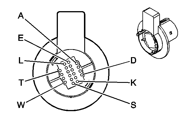
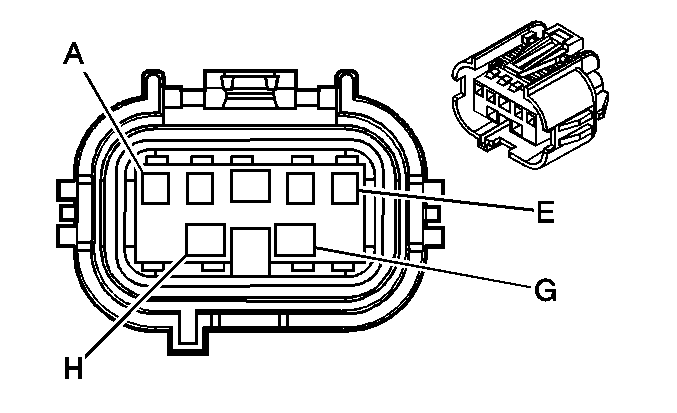
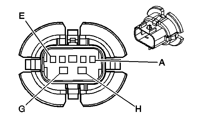
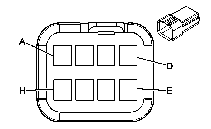
A | WHT | 423 | IC Timing Control | A | WHT | 423 | IC Timing Control | ||||||||
B | TAN/BLK | 424 | IC Timing Signal | B | TAN/BLK | 424 | IC Timing Signal | ||||||||
C | LT BLU/BLK | 647 | Medium Resolution Engine Speed Signal | C | LT BLU/BLK | 647 | Medium Resolution Engine Speed Signal | ||||||||
D | PPL/WHT | 430 | Low Resolution Engine Speed Signal | D | PPL/WHT | 430 | Low Resolution Engine Speed Signal | ||||||||
E | -- | -- | Not Used | E | WHT | 121 | Engine Speed Signal | ||||||||
F | BLK | 630 | Camshaft Position Signal | F | BLK | 630 | Camshaft Position Signal | ||||||||
G | RED/BLK | 453 | Low Reference | G | RED/BLK | 453 | Low Reference | ||||||||
H | PNK | 539 | Ignition 1 Voltage | H | PNK | 539 | Ignition 1 Voltage | ||||||||
|
| ||||||||||||||
|---|---|---|---|---|---|---|---|---|---|---|---|---|---|---|---|
Connector Part Information |
| Connector Part Information |
| ||||||||||||
Pin | Wire Color | Circuit No. | Function | Pin | Wire Color | Circuit No. | Function | ||||||||
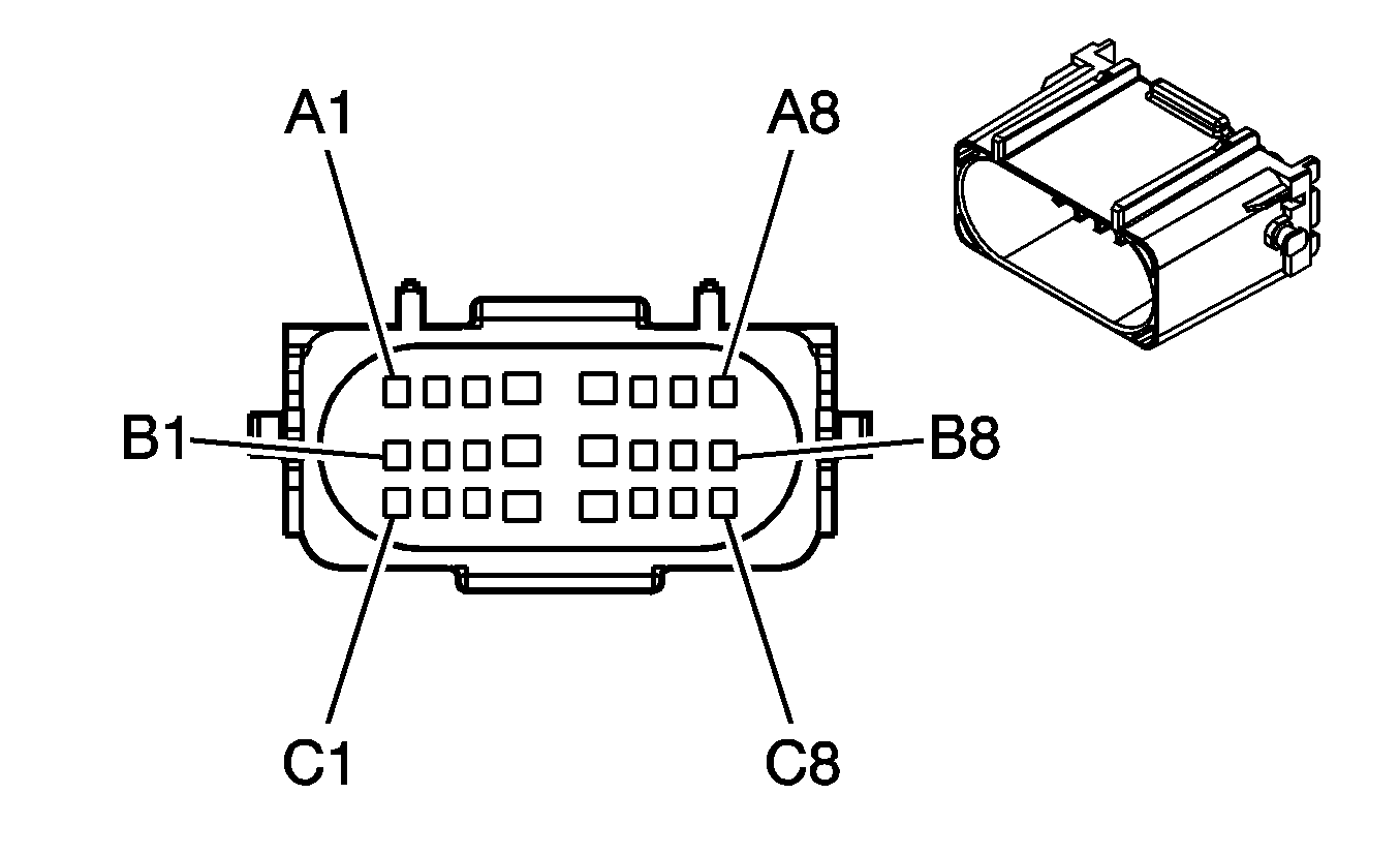
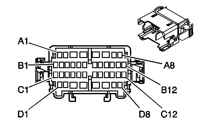
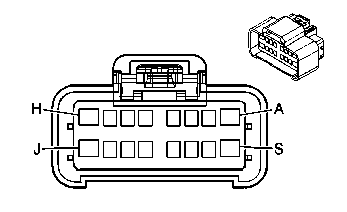
A1 | PNK | 1039 | Ignition 1 Voltage | A1 | PNK | 1039 | Ignition 1 Voltage | ||||||||
A2 | ORN | 140 | Battery Positive Voltage | A2 | ORN | 140 | Battery Positive Voltage | ||||||||
A3 | DK GRN | 335 | Low Speed Cooling Fan Relay Control | A3 | DK GRN | 335 | Low Speed Cooling Fan Relay Control | ||||||||
A4 | PPL | 6 | Starter Solenoid Crank Voltage | A4 | PPL | 6 | Starter Solenoid Crank Voltage | ||||||||
A5 | ORN | 1740 | Battery Positive Voltage | A5 | ORN | 1740 | Battery Positive Voltage | ||||||||
A6 | PNK | 839 | Ignition 1 Voltage | A6 | PNK | 839 | Ignition 1 Voltage | ||||||||
A7 | WHT | 1310 | EVAP Canister Vent Solenoid Control | A7 | WHT | 1310 | EVAP Canister Vent Solenoid Control | ||||||||
A8 | -- | -- | Not Used | A8 | -- | -- | Not Used | ||||||||
B1 | DK GRN/ WHT | 459 | A/C Compressor Clutch Relay Control | B1 | DK GRN/ WHT | 459 | A/C Compressor Clutch Relay Control | ||||||||
B2 | DK GRN/ WHT | 465 | Fuel Pump Relay Control | B2 | DK GRN/ WHT | 465 | Fuel Pump Relay Control | ||||||||
B3 | BRN | 436 | AIR Pump Relay Control | B3 | BRN | 436 | AIR Pump Relay Control (w/ NC8) | ||||||||
B4 | YEL/BLK | 625 | Starter Enable Relay Control | B4 | YEL/BLK | 625 | Starter Enable Relay Control | ||||||||
B5 | DK GRN | 59 | A/C Compressor Clutch Supply Voltage | B5 | DK GRN | 59 | A/C Compressor Clutch Supply Voltage | ||||||||
B6 | DK BLU | 473 | High Speed Cooling Fan Relay Control | B6 | DK BLU | 473 | High Speed Cooling Fan Relay Control | ||||||||
B7-B8 | -- | -- | Not Used | B7-B8 | -- | -- | Not Used | ||||||||
C1-C2 | -- | -- | Not Used | C1-C2 | -- | -- | Not Used | ||||||||
C3 | PNK | 739 | Ignition 1 Voltage | C3 | PNK | 739 | Ignition 1 Voltage | ||||||||
C4 | PNK | 539 | Ignition 1 Voltage | C4 | PNK | 539 | Ignition 1 Voltage | ||||||||
C5 | PNK | 639 | Ignition 1 Voltage | C5 | PNK | 639 | Ignition 1 Voltage | ||||||||
C6-C7 | -- | -- | Not Used | C6-C7 | -- | -- | Not Used | ||||||||
C8 | PNK | 739 | Ignition 1 Voltage | C8 | PNK | 739 | Ignition 1 Voltage | ||||||||
|
|
| ||||||||||||||
|---|---|---|---|---|---|---|---|---|---|---|---|---|---|---|---|
Connector Part Information |
| Connector Part Information |
| ||||||||||||
Pin | Wire Color | Circuit No. | Function | Pin | Wire Color | Circuit No. | Function | ||||||||
A | LT GRN | 1222 | 1-2 Shift Solenoid Valve Control | A | LT GRN | 1222 | 1-2 Shift Solenoid Valve Control | ||||||||
B | YEL/BLK | 1223 | 2-3 Shift Solenoid Valve Control | B | YEL | 1223 | 2-3 Shift Solenoid Valve Control | ||||||||
C | RED/BLK | 1228 | PC Solenoid Valve High Control | C | PPL | 1228 | PC Solenoid Valve High Control | ||||||||
D | LT BLU/WHT | 1229 | PC Solenoid Valve Low Control | D | LT BLU | 1229 | PC Solenoid Valve Low Control | ||||||||
E | PNK | 839 | Ignition 1 Voltage | E | RED | 839 | Ignition 1 Voltage | ||||||||
F | BLK/WHT | 771 | Transmission Range Switch Signal A | F | RED/BLK | 771 | Transmission Range Switch Signal A | ||||||||
G | YEL | 772 | Transmission Range Switch Signal B | G | DK GRN/ WHT | 772 | Transmission Range Switch Signal B | ||||||||
H | GRY | 773 | Transmission Range Switch Signal C | H | YEL/BLK | 773 | Transmission Range Switch Signal C | ||||||||
J | WHT | 776 | Transmission Range Switch Signal P | J | GRY/WHT | 776 | Transmission Range Switch Signal P | ||||||||
K | BLK/WHT | 451 | Ground | K | BLK/WHT | 1050 | Ground | ||||||||
L | YEL/BLK | 1227 | TFT Sensor Signal | L | BRN | 1227 | TFT Sensor Signal | ||||||||
M | BLK | 2762 | Low Reference | M | GRY | 452 | Low Reference | ||||||||
N | PNK | 1224 | Transmission Fluid Pressure Switch Signal A | N | PNK | 1224 | Transmission Fluid Pressure Switch Signal A | ||||||||
P | RED | 1226 | Transmission Fluid Pressure Switch Signal C | P | ORN | 1226 | Transmission Fluid Pressure Switch Signal C | ||||||||
R | DK BLU | 1225 | Transmission Fluid Pressure Switch Signal B | R | DK BLU | 1225 | Transmission Pressure Switch Signal B | ||||||||
S | RED/BLK | 1230 | AT ISS High Signal | S | BLK | 1230 | AT ISS High Signal | ||||||||
T | BRN | 418 | TCC PWM Solenoid Valve Control | T | TAN | 418 | TCC PWM Solenoid Valve Control | ||||||||
U | YEL | 657 | TCC Release Switch Signal | U | WHT | 1804 | TCC Release Switch Signal | ||||||||
V | DK BLU/ WHT | 1231 | AT ISS Low Signal | V | DK GRN | 1231 | AT ISS Low Signal | ||||||||
W | -- | -- | Not Used | W | -- | -- | Not Used | ||||||||
|
| ||||||||||||||
|---|---|---|---|---|---|---|---|---|---|---|---|---|---|---|---|
Connector Part Information |
| Connector Part Information |
| ||||||||||||
Pin | Wire Color | Circuit No. | Function | Pin | Wire Color | Circuit No. | Function | ||||||||
A | LT BLU | 2320 | Siren/Speaker Circuit-Provisional | A | LT BLU | 2320 | Siren/Speaker Circuit-Provisional | ||||||||
B | LT GRN | 2321 | Siren/Speaker Circuit-Provisional | B | LT GRN | 2321 | Siren/Speaker Circuit-Provisional | ||||||||
C | GRY | 2245 | Emergency Vehicle Front Lamps Supply Voltage | C | GRY | 2245 | Emergency Vehicle Front Lamps Supply Voltage | ||||||||
D | TAN | 2246 | Emergency Vehicle Front Lamps Supply Voltage | D | TAN | 2246 | Emergency Vehicle Front Lamps Supply Voltage | ||||||||
|
| ||||||||||||||
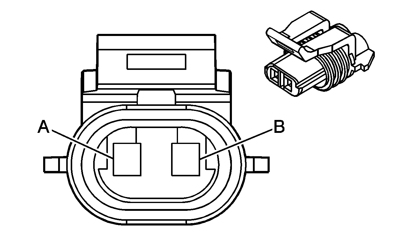
|---|---|---|---|---|---|---|---|---|---|---|---|---|---|---|---|
Connector Part Information |
| Connector Part Information |
| ||||||||||||
Pin | Wire Color | Circuit No. | Function | Pin | Wire Color | Circuit No. | Function | ||||||||
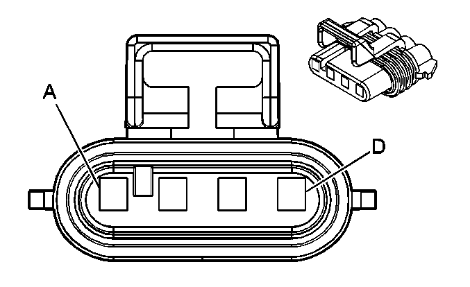
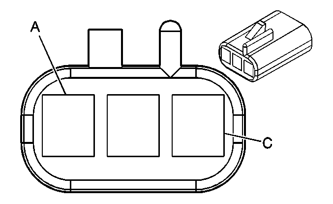
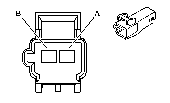
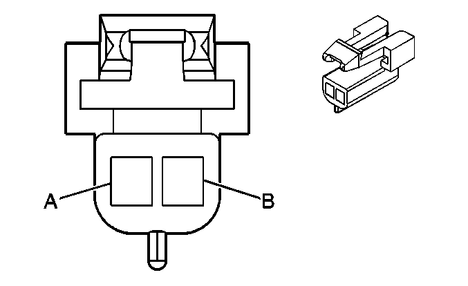
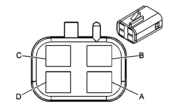
A | BLK | 2761 | Low Reference | A | BLK | 2761 | Low Reference | ||||||||
B | YEL | 410 | ECT Sensor Signal | B | YEL | 410 | ECT Sensor Signal | ||||||||
|
| ||||||||||||||
|---|---|---|---|---|---|---|---|---|---|---|---|---|---|---|---|
Connector Part Information |
| Connector Part Information |
| ||||||||||||
Pin | Wire Color | Circuit No. | Function | Pin | Wire Color | Circuit No. | Function | ||||||||
A1-A2 | -- | -- | Not Used | A1-A2 | -- | -- | Not Used | ||||||||
A3 | YEL | 243 | Accessory Voltage | A3 | YEL | 243 | Accessory Voltage | ||||||||
A4 | RED | 228 | Windshield Washer Pump Control | A4 | RED | 228 | Windshield Washer Pump Control | ||||||||
A5 | DK BLU | 241 | Ignition 3 Voltage | A5 | BRN | 241 | Ignition 3 Voltage | ||||||||
A6 | BLK | 28 | Horn Relay Control | A6 | BLK | 28 | Horn Relay Control | ||||||||
BLK | 28 | Horn Relay Control | |||||||||||||
A7-A8 | -- | -- | Not Used | A7-A8 | -- | -- | Not Used | ||||||||
B1 | -- | -- | Not Used | B1 | -- | -- | Not Used | ||||||||
B2 | GRY/BLK | 1458 | Instrument Panel Lamp Supply Voltage - 4 | B2 | GRY/BLK | 1458 | Instrument Panel Lamp Supply Voltage - 4 | ||||||||
B3 | YEL | 18 | Left Rear Stop/Turn Lamp Supply Voltage | B3 | YEL | 18 | Left Rear Stop/Turn Lamp Supply Voltage (Impala) | ||||||||
B4 | DK GRN | 19 | Right Rear Stop/Turn Lamp Supply Voltage | B4 | DK GRN | 19 | Right Rear Stop/Turn Lamp Supply Voltage (Impala) | ||||||||
B5 | WHT | 27 | Hazard Flasher Signal | B5 | BRN | 27 | Hazard Flasher Signal (Impala) | ||||||||
B6 | DK GRN | 113 | Windshield Wiper Switch Signal 1 | B6 | DK GRN | 113 | Windshield Wiper Switch Signal 1 | ||||||||
B7 | LT BLU | 14 | Left Turn Signal Lamps Supply Voltage | B7 | LT BLU | 14 | Left Turn Signal Lamps Supply Voltage (Impala) | ||||||||
B7 | YEL | 685 | Left Turn Signal Lamps Supply Voltage (Monte Carlo) | ||||||||||||
B8 | TAN/WHT | 816 | A/T Shift Lock Solenoid Supply Voltage | B8 | TAN/WHT | 816 | A/T Shift Lock Solenoid Supply Voltage (w/o D55) | ||||||||
B9 | GRY | 112 | Windshield Wiper Switch Signal 2 | B9 | GRY | 112 | Windshield Wiper Switch Signal 2 | ||||||||
B10 | DK BLU | 84 | Cruise Control Set/Coast Switch Signal | B10 | DK BLU | 84 | Cruise Control Set/Coast Switch Signal | ||||||||
B11 | PNK | 314 | Radio On Signal | B11 | PNK | 314 | Radio On Signal (w/o 9C1/9C3/9C6) | ||||||||
B12 | -- | -- | Not Used | B12 | -- | -- | Not Used | ||||||||
C1-C2 | -- | -- | Not Used | C1-C2 | -- | -- | Not Used | ||||||||
C3 | YEL | 1346 | Headlamp Supply Voltage | C3 | LT BLU | 1346 | Headlamp Supply Voltage | ||||||||
C4 | BRN | 1201 | Headlamp Low Beam Signal | C4 | DK BLU | 1201 | Headlamp Low Beam Signal | ||||||||
C5 | PPL | 16 | Turn Signal Flasher Signal | C5 | PPL | 16 | Turn Signal Flasher Signal | ||||||||
C6 | -- | -- | Not Used | C6 | -- | -- | Not Used | ||||||||
C7 | DK BLU | 15 | Right Turn Signal Lamps Supply Voltage | C7 | DK BLU | 15 | Right Turn Signal Lamps Supply Voltage (Impala) | ||||||||
C7 | TAN | 686 | Right Turn Signal Lamps Supply Voltage (Monte Carlo) | ||||||||||||
C8 | DK GRN/ WHT | 1135 | A/T Shift Lock Control Solenoid Supply Voltage | C8 | DK GRN/ WHT | 1135 | A/T Shift Lock Control Solenoid Supply Voltage (w/o D55) | ||||||||
C9 | BLK | 1050 | Ground | C9 | BLK | 1050 | Ground | ||||||||
C10 | GRY/BLK | 87 | Cruise Control Resume/Accel Switch Signal | C10 | GRY/BLK | 87 | Cruise Control Resume/Accel Switch Signal | ||||||||
C11 | DK BLU | 1796 | Steering Wheel Controls Signal | C11 | DK BLU | 1796 | Steering Wheel Controls Signal (w/o 9C1/9C3/9C6) | ||||||||
C12 | -- | -- | Not Used | C12 | -- | -- | Not Used | ||||||||
D1-D2 | -- | -- | Not Used | D1-D2 | -- | -- | Not Used | ||||||||
D3 | PPL | 92 | Windshield Wiper Motor High Speed | D3 | PPL | 92 | Windshield Wiper Motor High Speed | ||||||||
D4 | BLK | 1050 | Ground | D4 | BLK | 1050 | Ground | ||||||||
BLK | 1050 | Ground | |||||||||||||
D5 | PNK | 1200 | Headlamp High Beam Signal | D5 | PNK | 1200 | Headlamp High Beam Signal | ||||||||
PNK | 1200 | Headlamp High Beam Signal | |||||||||||||
D6 | GRY | 397 | Cruise Control On Switch Signal | D6 | GRY | 397 | Cruise Control On Switch Signal | ||||||||
GRY | 397 | Cruise Control On Switch Signal (Impala) | |||||||||||||
D7-D8 | -- | -- | Not Used | D7-D8 | -- | -- | Not Used | ||||||||
|
| ||||||||||||||
|---|---|---|---|---|---|---|---|---|---|---|---|---|---|---|---|
Connector Part Information |
| Connector Part Information |
| ||||||||||||
Pin | Wire Color | Circuit No. | Function | Pin | Wire Color | Circuit No. | Function | ||||||||
A | BLK | 28 | Horn Relay Control | A | BLK | 28 | Horn Relay Control | ||||||||
|
| ||||||||||||||
|---|---|---|---|---|---|---|---|---|---|---|---|---|---|---|---|
Connector Part Information |
| Connector Part Information |
| ||||||||||||
Pin | Wire Color | Circuit No. | Function | Pin | Wire Color | Circuit No. | Function | ||||||||
A1 | YEL | 3024 | IP Module - Stage 1 - Low Control | A1 | ORN | 3024 | IP Module - Stage 1 - Low Control | ||||||||
A2 | ORN | 3025 | IP Module - Stage 1 - High Control | A2 | YEL | 3025 | IP Module - Stage 1 - High Control | ||||||||
B1 | GRY | 3026 | IP Module - Stage 2 - Low Control | B1 | PPL | 3026 | IP Module - Stage 2 - Low Control | ||||||||
B2 | PPL | 3027 | IP Module - Stage 2 - High Control | B2 | GRY | 3027 | IP Module - Stage 2 - High Control | ||||||||
|
|
| ||||||||||||||
|---|---|---|---|---|---|---|---|---|---|---|---|---|---|---|---|
Connector Part Information |
| Connector Part Information |
| ||||||||||||
Pin | Wire Color | Circuit No. | Function | Pin | Wire Color | Circuit No. | Function | ||||||||
A1 | TAN | 3021 | Steering Wheel Module - Stage1 - High Control | A1 | TAN | 3021 | Steering Wheel Module - Stage1 - High Control | ||||||||
A2 | BRN | 3020 | Steering Wheel Module - Stage1 - Low Control | A2 | BRN | 3020 | Steering Wheel Module - Stage1 - Low Control | ||||||||
B1 | WHT | 3023 | Steering Wheel Module - Stage2 - High Control | B1 | WHT | 3023 | Steering Wheel Module - Stage2 - High Control | ||||||||
B2 | PNK | 3022 | Steering Wheel Module - Stage2 - Low Control | B2 | PNK | 3022 | Steering Wheel Module - Stage2 - Low Control | ||||||||
|
|
| ||||||||||||||
|---|---|---|---|---|---|---|---|---|---|---|---|---|---|---|---|
Connector Part Information |
| Connector Part Information |
| ||||||||||||
Pin | Wire Color | Circuit No. | Function | Pin | Wire Color | Circuit No. | Function | ||||||||
A1 | YEL | 3025 | IP Module - Stage 1 - High Control | A1 | YEL | 3025 | IP Module - Stage 1 - High Control | ||||||||
A2 | ORN | 3024 | IP Module - Stage 1 - Low Control | A2 | ORN | 3024 | IP Module - Stage 1 - Low Control | ||||||||
B1 | GRY | 3027 | IP Module - Stage 2 - High Control | B1 | GRY | 3027 | IP Module - Stage 2 - High Control | ||||||||
B2 | PPL | 3026 | IP Module - Stage 2 - Low Control | B2 | PPL | 3026 | IP Module - Stage 2 - Low Control | ||||||||
|
| ||||||||||||||
|---|---|---|---|---|---|---|---|---|---|---|---|---|---|---|---|
Connector Part Information |
| Connector Part Information |
| ||||||||||||
Pin | Wire Color | Circuit No. | Function | Pin | Wire Color | Circuit No. | Function | ||||||||
A | LT BLU | 1405 | Remote Playback Device Audio Common Signal | A | LT BLU | 1405 | Remote Playback Device Audio Common Signal | ||||||||
B | LT GRN | 1407 | Remote Playback Device Right Audio Signal | B | LT GRN | 1407 | Remote Playback Device Right Audio Signal | ||||||||
C | ORN/BLK | 1406 | Remote Playback Device Left Audio Signal | C | ORN/BLK | 1406 | Remote Playback Device Left Audio Signal | ||||||||
D | BARE | 2012 | Drain Wire | D | BARE | 2012 | Drain Wire | ||||||||
E | GRY | 2289 | Audio Class 2 Serial Data | E | GRY | 2289 | Audio Class 2 Serial Data | ||||||||
F | -- | -- | Not Used | F | -- | -- | Not Used | ||||||||
|
| ||||||||||||||
|---|---|---|---|---|---|---|---|---|---|---|---|---|---|---|---|
Connector Part Information |
| Connector Part Information |
| ||||||||||||
Pin | Wire Color | Circuit No. | Function | Pin | Wire Color | Circuit No. | Function | ||||||||
A | GRY | 8 | Instrument Panel Lamp Supply Voltage - 1 | A | GRY | 8 | Instrument Panel Lamp Supply Voltage - 1 | ||||||||
B | ORN | 340 | Battery Positive Voltage | B | ORN | 340 | Battery Positive Voltage | ||||||||
C | BLK | 1050 | Ground | C | BLK | 1050 | Ground | ||||||||
D | ORN | 1640 | Battery Positive Voltage | D | ORN | 1640 | Battery Positive Voltage | ||||||||
E | BLK | 1050 | Ground | E | BLK | 1050 | Ground | ||||||||
F | BLK | 1050 | Ground | F | BLK | 1050 | Ground | ||||||||
G-H | -- | -- | Not Used | G-H | -- | -- | Not Used | ||||||||
|
| ||||||||||||||
|---|---|---|---|---|---|---|---|---|---|---|---|---|---|---|---|
Connector Part Information |
| Connector Part Information |
| ||||||||||||
Pin | Wire Color | Circuit No. | Function | Pin | Wire Color | Circuit No. | Function | ||||||||
A | YEL | 18 | Left Rear Stop/Turn Lamp Supply Voltage | A | YEL | 18 | Left Rear Stop/Turn Lamp Supply Voltage | ||||||||
B | DK GRN | 19 | Right Rear Stop/Turn Lamp Supply Voltage | B | DK GRN | 19 | Right Rear Stop/Turn Lamp Supply Voltage | ||||||||
|
|
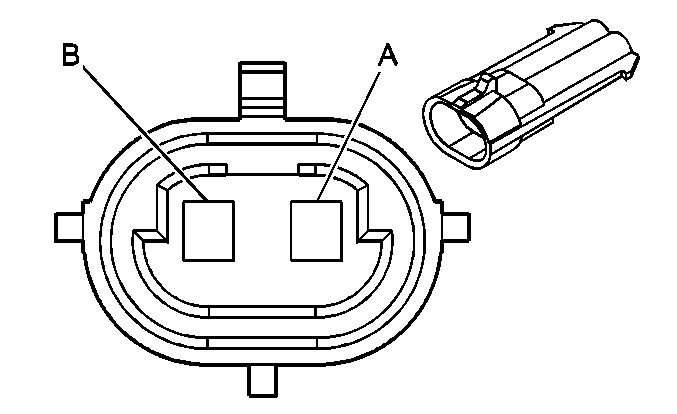
| ||||||||||||||
|---|---|---|---|---|---|---|---|---|---|---|---|---|---|---|---|
Connector Part Information |
| Connector Part Information |
| ||||||||||||
Pin | Wire Color | Circuit No. | Function | Pin | Wire Color | Circuit No. | Function | ||||||||
A | PNK | 2322 | Emergency Vehicle Rear Lamps Supply Voltage | A | PNK | 2322 | Emergency Vehicle Rear Lamps Supply Voltage | ||||||||
B | LT BLU | 2320 | Siren/Speaker Circuit-Provisional | B | LT BLU | 2320 | Siren/Speaker Circuit-Provisional | ||||||||
C | LT GRN | 2321 | Siren/Speaker Circuit-Provisional | C | LT GRN | 2321 | Siren/Speaker Circuit-Provisional | ||||||||
D | GRY | 2245 | Emergency Vehicle Front Lamps Supply Voltage | D | GRY | 2245 | Emergency Vehicle Front Lamps Supply Voltage | ||||||||
E | TAN | 2246 | Emergency Vehicle Front Lamps Supply Voltage | E | TAN | 2246 | Emergency Vehicle Front Lamps Supply Voltage | ||||||||
F | LT BLU | 2624 | Emergency Vehicle Rear Lamps Supply Voltage | F | LT BLU | 2624 | Emergency Vehicle Rear Lamps Supply Voltage | ||||||||
|
| ||||||||||||||
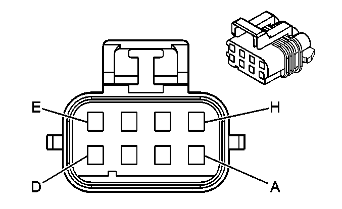
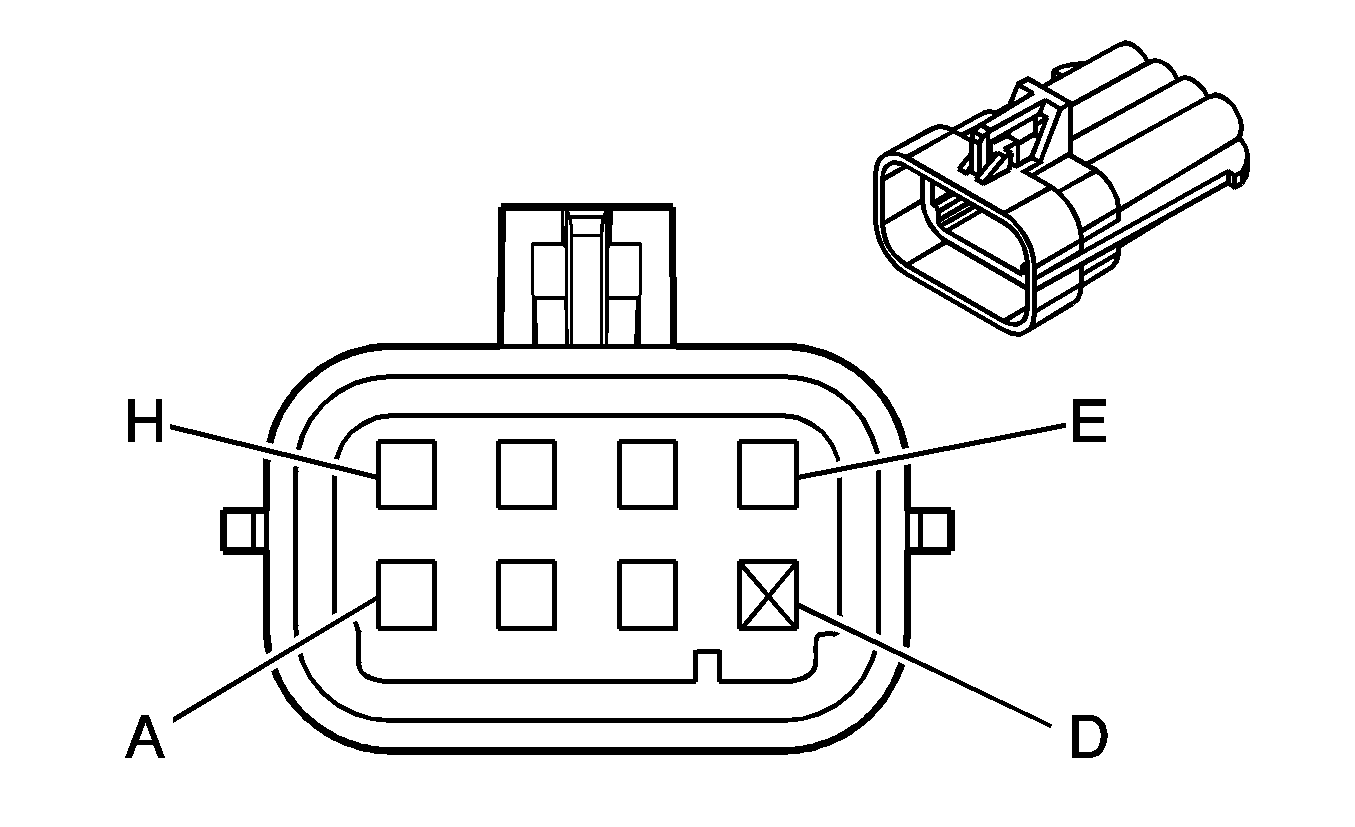
|---|---|---|---|---|---|---|---|---|---|---|---|---|---|---|---|
Connector Part Information |
| Connector Part Information |
| ||||||||||||
Pin | Wire Color | Circuit No. | Function | Pin | Wire Color | Circuit No. | Function | ||||||||
A | GRY | 118 | Left Front Speaker Output (-) | A | GRY | 118 | Left Front Speaker Output (-) | ||||||||
B | TAN | 201 | Left Front Speaker Output (+) | B | TAN | 201 | Left Front Speaker Output (+) | ||||||||
C | DK GRN | 117 | Right Front Speaker Output (-) | C | DK GRN | 117 | Right Front Speaker Output (-) | ||||||||
D | LT GRN | 200 | Right Front Speaker Output (+) | D | LT GRN | 200 | Right Front Speaker Output (+) | ||||||||
E | YEL | 116 | Left Rear Speaker Output (-) | E | YEL | 116 | Left Rear Speaker Output (-) | ||||||||
F | BRN | 199 | Left Rear Speaker Output (+) | F | BRN | 199 | Left Rear Speaker Output (+) | ||||||||
G | LT BLU | 115 | Right Rear Speaker Output (-) | G | LT BLU | 115 | Right Rear Speaker Output (-) | ||||||||
H | DK BLU | 46 | Right Rear Speaker Output (+) | H | DK BLU | 46 | Right Rear Speaker Output (+) | ||||||||
|
| ||||||||||||||
|---|---|---|---|---|---|---|---|---|---|---|---|---|---|---|---|
Connector Part Information |
| Connector Part Information |
| ||||||||||||
Pin | Wire Color | Circuit No. | Function | Pin | Wire Color | Circuit No. | Function | ||||||||
A1 | -- | -- | Not Used | A1 | -- | -- | Not Used | ||||||||
A2 | BLK | 2050 | Ground | A2 | BLK | 2050 | Ground | ||||||||
A3 | YEL | 343 | Accessory Voltage | A3 | YEL | 343 | Accessory Voltage | ||||||||
A4 | DK BLU | 1307 | Power Window Master Switch Lockout Signal | A4 | DK BLU | 1307 | Power Window Master Switch Lockout Signal | ||||||||
A5 | PPL | 169 | Power Window Master Switch Left Rear Down Signal | A5 | PPL | 169 | Power Window Master Switch Left Rear Down Signal | ||||||||
A6 | DK GRN | 168 | Power Window Master Switch Left Rear Up Signal | A6 | DK GRN | 168 | Power Window Master Switch Left Rear Up Signal | ||||||||
A7-A8 | -- | -- | Not Used | A7-A8 | -- | -- | Not Used | ||||||||
B1 | -- | -- | Not Used | B1 | -- | -- | Not Used | ||||||||
B2 | GRY | 118 | Left Front Speaker Output (-) | B2 | GRY | 118 | Left Front Speaker Output (-) (w/ UX7/U62) | ||||||||
B2 | LT GRN/BLK | 1794 | [Left Subwoofer Speaker Output (-) (w/ UQ3) | ||||||||||||
B3-B4 | -- | -- | Not Used | B3-B4 | -- | -- | Not Used | ||||||||
B5 | BLK/WHT | 1251 | Ground (w/ UA6) | B5 | BLK/WHT | 1251 | Ground | ||||||||
B6 | ORN | 267 | Heated Mirror/Rear Defog Relay Coil Suppy Voltage | B6 | ORN | 267 | Heated Mirror/Rear Defog Relay Coil Suppy Voltage (w/o 9C1/9C3/9C6) | ||||||||
B7 | -- | -- | Not Used | B7 | -- | -- | Not Used | ||||||||
B8 | ORN | 2040 | Battery Positive Voltage | B8 | ORN | 2040 | Battery Positive Voltage | ||||||||
B9 | RED/WHT | 881 | Right Mirror Motor Right Control | B9 | RED/WHT | 881 | Right Mirror Motor Right Control | ||||||||
B10 | GRY | 8 | Instrument Panel Lamp Supply Voltage - 1 | B10 | GRY | 8 | Instrument Panel Lamp Supply Voltage - 1 | ||||||||
B11 | TAN | 694 | Driver Door Lock Actuator Unlock Control | B11 | TAN | 694 | Driver Door Lock Actuator Unlock Control | ||||||||
B12 | -- | -- | Not Used | B12 | -- | -- | Not Used | ||||||||
C1 | -- | -- | Not Used | C1 | -- | -- | Not Used | ||||||||
C2 | TAN | 201 | Left Front Speaker Output (+) | C2 | TAN | 201 | Left Front Speaker Output (+) (w/ UX7/U62) | ||||||||
C2 | DK BLU/WHT | 346 | Left Subwoofer Speaker Output (+) (w/ UQ3) | ||||||||||||
C3 | ORN/BLK | 781 | Door Lock Switch Signal | C3 | ORN/BLK | 781 | Door Lock Switch Signal | ||||||||
C4 | DK BLU | 49 | Driver Door Open Switch Signal | C4 | DK BLU | 49 | Driver Door Open Switch Signal | ||||||||
C5 | LT GRN | 262 | Driver Door Key Switch Signal (w/ UA6) | C5 | LT GRN | 262 | Driver Door Key Switch Signal (w/o 9C1/9C3/9C6) | ||||||||
C6 | GRY | 8 | Instrument Panel Lamp Supply Voltage - 1 | C6 | GRY | 8 | Instrument Panel Lamp Supply Voltage - 1 | ||||||||
C7 | -- | -- | Not Used | C7 | -- | -- | Not Used | ||||||||
C8 | BLK/WHT | 1251 | Ground | C8 | BLK/WHT | 1251 | Ground | ||||||||
C9 | GRY | 90 | Right Mirror Motor Left Control | C9 | GRY | 90 | Right Mirror Motor Left Control | ||||||||
C10 | PPL/WHT | 889 | Right Mirror Motor Down Control | C10 | PPL/WHT | 889 | Right Mirror Motor Down Control | ||||||||
C11 | GRY | 295 | Door Lock Actuator Lock Control | C11 | GRY | 295 | Door Lock Actuator Lock Control | ||||||||
C12 | -- | -- | Not Used | C12 | -- | -- | Not Used | ||||||||
D1-D2 | -- | -- | Not Used | D1-D2 | -- | -- | Not Used | ||||||||
D3 | LT GRN | 170 | Power Window Master Switch Right Rear Up Signal | D3 | LT GRN | 170 | Power Window Master Switch Right Rear Up Signal | ||||||||
D4 | PPL | 171 | Power Window Master Switch Right Rear Down Signal | D4 | PPL | 171 | Power Window Master Switch Right Rear Down Signal | ||||||||
D5 | LT BLU | 166 | Power Window Master Switch Right Front Up Signal | D5 | LT BLU | 166 | Power Window Master Switch Right Front Up Signal | ||||||||
D6 | TAN | 167 | Power Window Master Switch Right Front Down Signal | D6 | TAN | 167 | Power Window Master Switch Right Front Down Signal | ||||||||
D7-D8 | -- | -- | Not Used | D7-D8 | -- | -- | Not Used | ||||||||
|
|
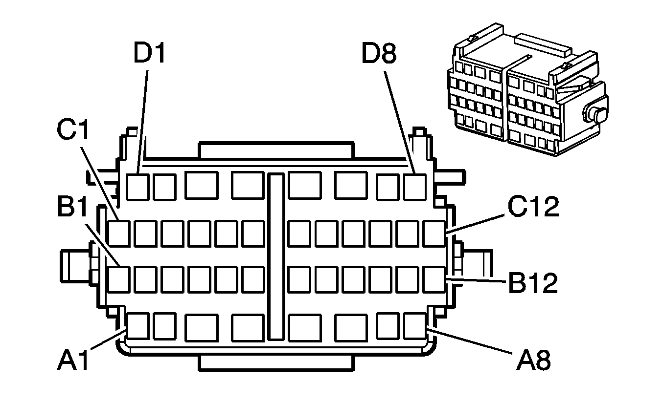
| ||||||||||||||
|---|---|---|---|---|---|---|---|---|---|---|---|---|---|---|---|
Connector Part Information |
| Connector Part Information |
| ||||||||||||
Pin | Wire Color | Circuit No. | Function | Pin | Wire Color | Circuit No. | Function | ||||||||
A1 | -- | -- | Not Used | A1 | -- | -- | Not Used | ||||||||
A2 | BLK | 2050 | Ground | A2 | BLK | 2050 | Ground | ||||||||
A3 | -- | -- | Not Used | A3 | -- | -- | Not Used | ||||||||
A4 | YEL | 343 | Accessory Voltage | A4 | YEL | 343 | Accessory Voltage | ||||||||
A5-A8 | -- | -- | Not Used | A5-A8 | -- | -- | Not Used | ||||||||
B1 | -- | -- | Not Used | B1 | -- | -- | Not Used | ||||||||
B2 | GRY | 118 | Left Front Speaker Output (-) | B2 | GRY | 118 | Left Front Speaker Output (-) (w/ UW6) | ||||||||
B2 | LT GRN/BLK | 1794 | Left Subwoofer Speaker Output (-) (w/ UQ3) | ||||||||||||
B3-B4 | -- | -- | Not Used | B3-B4 | -- | -- | Not Used | ||||||||
B5 | BLK/WHT | 1251 | Ground | B5 | BLK/WHT | 1251 | Ground | ||||||||
B6 | ORN | 267 | Heated Mirror/Rear Defog Relay Coil Suppy Voltage | B6 | ORN | 267 | Heated Mirror/Rear Defog Relay Coil Suppy Voltage | ||||||||
B7 | -- | -- | Not Used | B7 | -- | -- | Not Used | ||||||||
B8 | ORN | 2040 | Battery Positive Voltage | B8 | ORN | 2040 | Battery Positive Voltage | ||||||||
B9 | RED/WHT | 881 | Right Mirror Motor Right Control | B9 | RED/WHT | 881 | Right Mirror Motor Right Control | ||||||||
B10 | GRY | 8 | Instrument Panel Lamp Supply Voltage - 1 | B10 | GRY | 8 | Instrument Panel Lamp Supply Voltage - 1 | ||||||||
B11 | TAN | 694 | Driver Door Lock Actuator Unlock Control | B11 | TAN | 694 | Driver Door Lock Actuator Unlock Control | ||||||||
B12 | -- | -- | Not Used | B12 | -- | -- | Not Used | ||||||||
C1 | -- | -- | Not Used | C1 | -- | -- | Not Used | ||||||||
C2 | TAN | 201 | Left Front Speaker Output (+) | C2 | TAN | 201 | Left Front Speaker Output (+) (w/ UW6) | ||||||||
C2 | DK BLU/WHT | 346 | Left Subwoofer Speaker Output (+) (w/ UQ3) | ||||||||||||
C3 | ORN/BLK | 781 | Door Lock Switch Signal | C3 | ORN/BLK | 781 | Door Lock Switch Signal | ||||||||
C4 | DK BLU | 49 | Driver Door Open Switch Signal | C4 | DK BLU | 49 | Driver Door Open Switch Signal | ||||||||
C5 | LT GRN | 262 | Driver Door Key Switch Signal (w/ UA6) | C5 | LT GRN | 262 | Driver Door Key Switch Signal | ||||||||
C6 | GRY | 8 | Instrument Panel Lamp Supply Voltage - 1 | C6 | GRY | 8 | Instrument Panel Lamp Supply Voltage - 1 | ||||||||
C7 | -- | -- | Not Used | C7 | -- | -- | Not Used | ||||||||
C8 | BLK/WHT | 1251 | Ground (w/ UA6) | C8 | BLK/WHT | 1251 | Ground | ||||||||
C9 | GRY | 90 | Right Mirror Motor Left Control | C9 | GRY | 90 | Right Mirror Motor Left Control | ||||||||
C10 | PPL/WHT | 889 | Right Mirror Motor Down Control | C10 | PPL/WHT | 889 | Right Mirror Motor Down Control | ||||||||
C11 | GRY | 295 | Door Lock Actuator Lock Control | C11 | GRY | 295 | Door Lock Actuator Lock Control | ||||||||
C12 | -- | -- | Not Used | C12 | -- | -- | Not Used | ||||||||
D1 | YEL | 2131 | Side Impact Sensing Module - Left -Voltage (w/ AW6) | D1 | YEL | 2131 | Side Impact Sensing Module - Left -Voltage (w/ AW6) | ||||||||
D2 | WHT | 2132 | Side Impact Sensing Module - Left - Signal (w/ AW6) | D2 | WHT | 2132 | Side Impact Sensing Module - Left - Signal (w/ AW6) | ||||||||
D3-D4 | -- | -- | Not Used | D3-D4 | -- | -- | Not Used | ||||||||
D5 | LT BLU | 166 | Power Window Master Switch Right Front Up Signal | D5 | LT BLU | 166 | Power Window Master Switch Right Front Up Signal | ||||||||
D6 | TAN | 167 | Power Window Master Switch Right Front Down Signal | D6 | TAN | 167 | Power Window Master Switch Right Front Down Signal | ||||||||
D7-D8 | -- | -- | Not Used | D7-D8 | -- | -- | Not Used | ||||||||
|
|
| ||||||||||||||
|---|---|---|---|---|---|---|---|---|---|---|---|---|---|---|---|
Connector Part Information |
| Connector Part Information |
| ||||||||||||
Pin | Wire Color | Circuit No. | Function | Pin | Wire Color | Circuit No. | Function | ||||||||
A1 | -- | -- | Not Used | A1 | -- | -- | Not Used | ||||||||
A2 | BLK | 1750 | Ground | A2 | BLK | 1750 | Ground | ||||||||
A3 | -- | -- | Not Used | A3 | -- | -- | Not Used | ||||||||
A4 | DK BLU | 1307 | Power Window Master Switch Lockout Signal | A4 | DK BLU | 1307 | Power Window Master Switch Lockout Signal | ||||||||
A5-A8 | -- | -- | Not Used | A5-A8 | -- | -- | Not Used | ||||||||
B1 | -- | -- | Not Used | B1 | -- | -- | Not Used | ||||||||
B2 | DK GRN | 117 | Right Front Speaker Output (-) | B2 | DK GRN | 117 | Right Front Speaker Output (-) (w/ UX7/U62) | ||||||||
B2 | LT BLU/BLK | 315 | Right Subwoofer Speaker Output (-) (w/ UQ3) | ||||||||||||
B3 | -- | -- | Not Used | B3 | -- | -- | Not Used | ||||||||
B4 | DK BLU/ WHT | 727 | Door Open Switch Signal | B4 | DK BLU/ WHT | 727 | Door Open Switch Signal | ||||||||
B5 | BLK/WHT | 1251 | Ground (w/ UA6) | B5 | BLK/WHT | 1251 | Ground | ||||||||
B6 | ORN | 267 | Heated Mirror/Rear Defog Relay Coil Suppy Voltage | B6 | ORN | 267 | Heated Mirror/Rear Defog Relay Coil Suppy Voltage (w/o 9C1/9C3/9C6) | ||||||||
B7-B8 | -- | -- | Not Used | B7-B8 | -- | -- | Not Used | ||||||||
B9 | RED/WHT | 881 | Right Mirror Motor Right Control | B9 | RED/WHT | 881 | Right Mirror Motor Right Control | ||||||||
B10 | GRY | 8 | Instrument Panel Lamp Supply Voltage - 1 | B10 | GRY | 8 | Instrument Panel Lamp Supply Voltage - 1 | ||||||||
B11 | TAN | 294 | Door Lock Actuator Unlock Control | B11 | TAN | 294 | Door Lock Actuator Unlock Control | ||||||||
B12 | -- | -- | Not Used | B12 | -- | -- | Not Used | ||||||||
C1 | -- | -- | Not Used | C1 | -- | -- | Not Used | ||||||||
C2 | LT GRN | 200 | Right Front Speaker Output (+) | C2 | LT GRN | 200 | Right Front Speaker Output (+) (w UX7/U62) | ||||||||
C2 | DK GRN | 1795 | Right Subwoofer Speaker Output (+) (w/ UQ3) | ||||||||||||
C3 | ORN/BLK | 781 | Door Lock Switch Signal | C3 | ORN/BLK | 781 | Door Lock Switch Signal | ||||||||
C4 | -- | -- | Not Used | C4 | -- | -- | Not Used | ||||||||
C5 | LT GRN | 262 | Driver Door Key Switch Signal (w/ UA6) | C5 | LT GRN | 262 | Driver Door Key Switch Signal (w/o 9C1/9C3/9C6) | ||||||||
C6-C7 | -- | -- | Not Used | C6-C7 | -- | -- | Not Used | ||||||||
C8 | BLK/WHT | 1251 | Ground | C8 | BLK/WHT | 1251 | Ground | ||||||||
C9 | GRY | 90 | Right Mirror Motor Left Control | C9 | GRY | 90 | Right Mirror Motor Left Control | ||||||||
C10 | PPL/WHT | 889 | Right Mirror Motor Down Control | C10 | PPL/WHT | 889 | Right Mirror Motor Down Control | ||||||||
C11 | GRY | 295 | Door Lock Actuator Lock Control | C11 | GRY | 295 | Door Lock Actuator Lock Control | ||||||||
C12 | -- | -- | Not Used | C12 | -- | -- | Not Used | ||||||||
D1-D4 | -- | -- | Not Used | D1-D4 | -- | -- | Not Used | ||||||||
D5 | LT BLU | 166 | Power Window Master Switch Right Front Up Signal | D5 | LT BLU | 166 | Power Window Master Switch Right Front Up Signal | ||||||||
D6 | TAN | 167 | Power Window Master Switch Right Front Down Signal | D6 | TAN | 167 | Power Window Master Switch Right Front Down Signal | ||||||||
D7-D8 | -- | -- | Not Used | D7-D8 | -- | -- | Not Used | ||||||||
|
|
| ||||||||||||||
|---|---|---|---|---|---|---|---|---|---|---|---|---|---|---|---|
Connector Part Information |
| Connector Part Information |
| ||||||||||||
Pin | Wire Color | Circuit No. | Function | Pin | Wire Color | Circuit No. | Function | ||||||||
A1 | -- | -- | Not Used | A1 | -- | -- | Not Used | ||||||||
A2 | BLK | 1750 | Ground | A2 | BLK | 1750 | Ground | ||||||||
A3 | -- | -- | Not Used | A3 | -- | -- | Not Used | ||||||||
A4 | YEL | 343 | Accessory Voltage | A4 | YEL | 343 | Accessory Voltage | ||||||||
A5-A8 | -- | -- | Not Used | A5-A8 | -- | -- | Not Used | ||||||||
B1 | -- | -- | Not Used | B1 | -- | -- | Not Used | ||||||||
B2 | DK GRN | 117 | Right Front Speaker Output (-) | B2 | DK GRN | 117 | Right Front Speaker Output (-) (w/ UW6) | ||||||||
B2 | LT BLU/BLK | 315 | Right Subwoofer Speaker Output (-) (w/ UQ3) | ||||||||||||
B3 | -- | -- | Not Used | B3 | -- | -- | Not Used | ||||||||
B4 | DK BLU/ WHT | 727 | Door Open Switch Signal | B4 | DK BLU/ WHT | 727 | Door Open Switch Signal | ||||||||
B5 | BLK/WHT | 1251 | Ground (w/ UA6) | B5 | BLK/WHT | 1251 | Ground | ||||||||
B6 | ORN | 267 | Heated Mirror/Rear Defog Relay Coil Suppy Voltage | B6 | ORN | 267 | Heated Mirror/Rear Defog Relay Coil Suppy Voltage | ||||||||
B7-B8 | -- | -- | Not Used | B7-B8 | -- | -- | Not Used | ||||||||
B9 | RED/WHT | 881 | Right Mirror Motor Right Control | B9 | RED/WHT | 881 | Right Mirror Motor Right Control | ||||||||
B10 | GRY | 8 | Instrument Panel Lamp Supply Voltage - 1 | B10 | GRY | 8 | Instrument Panel Lamp Supply Voltage - 1 | ||||||||
B11 | TAN | 294 | Door Lock Actuator Unlock Control | B11 | TAN | 294 | Door Lock Actuator Unlock Control | ||||||||
B12 | -- | -- | Not Used | B12 | -- | -- | Not Used | ||||||||
C1 | -- | -- | Not Used | C1 | -- | -- | Not Used | ||||||||
C2 | LT GRN | 200 | Right Front Speaker Output (+) | C2 | LT GRN | 200 | Right Front Speaker Output (+) (w/ UW6) | ||||||||
C2 | DK GRN | 1795 | Right Subwoofer Speaker Output (+) (w/ UQ3) | ||||||||||||
C3 | ORN/BLK | 781 | Door Lock Switch Signal | C3 | ORN/BLK | 781 | Door Lock Switch Signal | ||||||||
C4 | -- | -- | Not Used | C4 | -- | -- | Not Used | ||||||||
C5 | LT GRN | 262 | Door Key Switch Signal (w/ UA6) | C5 | LT GRN | 262 | Door Key Switch Signal | ||||||||
C6-C7 | -- | -- | Not Used | C6-C7 | -- | -- | Not Used | ||||||||
C8 | BLK/WHT | 1251 | Ground | C8 | BLK/WHT | 1251 | Ground | ||||||||
C9 | GRY | 90 | Right Mirror Motor Left Control | C9 | GRY | 90 | Right Mirror Motor Left Control | ||||||||
C10 | PPL/WHT | 889 | Right Mirror Motor Down Control | C10 | PPL/WHT | 889 | Right Mirror Motor Down Control | ||||||||
C11 | GRY | 295 | Door Lock Actuator Lock Control | C11 | GRY | 295 | Door Lock Actuator Lock Control | ||||||||
C12 | -- | -- | Not Used | C12 | -- | -- | Not Used | ||||||||
D1-D4 | -- | -- | Not Used | D1-D4 | -- | -- | Not Used | ||||||||
D5 | LT BLU | 166 | Power Window Master Switch Right Front Up Signal | D5 | LT BLU | 166 | Power Window Master Switch Right Front Up Signal | ||||||||
D6 | TAN | 167 | Power Window Master Switch Right Front Down Signal | D6 | TAN | 167 | Power Window Master Switch Right Front Down Signal | ||||||||
D7-D8 | -- | -- | Not Used | D7-D8 | -- | -- | Not Used | ||||||||
|
| ||||||||||||||
|---|---|---|---|---|---|---|---|---|---|---|---|---|---|---|---|
Connector Part Information |
| Connector Part Information |
| ||||||||||||
Pin | Wire Color | Circuit No. | Function | Pin | Wire Color | Circuit No. | Function | ||||||||
A | YEL | 18 | Left Rear Stop/Turn Lamp Supply Voltage | A | YEL | 18 | Left Rear Stop/Turn Lamp Supply Voltage | ||||||||
B | DK GRN | 19 | Right Rear Stop/Turn Lamp Supply Voltage | B | DK GRN | 19 | Right Rear Stop/Turn Lamp Supply Voltage | ||||||||
C | LT BLU | 2624 | Emergency Vehicle Rear Lamps Supply Voltage | C | LT BLU | 2624 | Emergency Vehicle Rear Lamps Supply Voltage | ||||||||
|
| ||||||||||||||
|---|---|---|---|---|---|---|---|---|---|---|---|---|---|---|---|
Connector Part Information |
| Connector Part Information |
| ||||||||||||
Pin | Wire Color | Circuit No. | Function | Pin | Wire Color | Circuit No. | Function | ||||||||
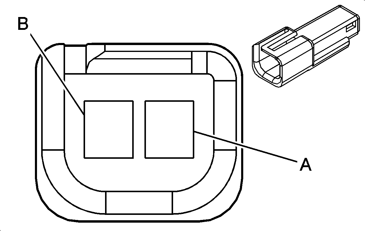
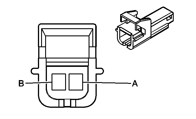
A | RED | 302 | Battery Positive Voltage | A | RED | 302 | Battery Positive Voltage | ||||||||
B | RED | 702 | Battery Positive Voltage | B | RED | 702 | Battery Positive Voltage | ||||||||
|
|
| ||||||||||||||
|---|---|---|---|---|---|---|---|---|---|---|---|---|---|---|---|
Connector Part Information |
| Connector Part Information |
| ||||||||||||
Pin | Wire Color | Circuit No. | Function | Pin | Wire Color | Circuit No. | Function | ||||||||
A | ORN/BLK | 1840 | Battery Positive Voltage (w/o 9C1/9C3/9C6) | A | ORN | 1840 | Battery Positive Voltage (w/o 9C1/9C3/9C6) | ||||||||
B | -- | -- | Not Used | B | -- | -- | Not Used | ||||||||
C | ORN | 2340 | Battery Positive Voltage | C | ORN | 2340 | Battery Positive Voltage | ||||||||
D | ORN | 480 | Load Management Control (Impala w/o 9C1/9C3/9C6) | D | ORN | 480 | Load Management Control (Impala w/o 9C1/9C3/9C6) | ||||||||
E | BLK/WHT | 238 | Seat Belt Switch - Left - Signal | E | BLK/WHT | 238 | Seat Belt Switch - Left - Signal | ||||||||
F | BLK | 1550 | Ground | F | BLK | 1550 | Ground | ||||||||
G | PNK | 1501 | Driver Heated Seat High/Low Signal (Monte Carlo) | G | PNK | 1501 | Driver Heated Seat High/Low Signal (Monte Carlo) | ||||||||
H | LT BLU | 1462 | Heated Seat Switch Signal (Monte Carlo) | H | LT BLU | 1462 | Heated Seat Switch Signal (Monte Carlo) | ||||||||
|
|
| ||||||||||||||
|---|---|---|---|---|---|---|---|---|---|---|---|---|---|---|---|
Connector Part Information |
| Connector Part Information |
| ||||||||||||
Pin | Wire Color | Circuit No. | Function | Pin | Wire Color | Circuit No. | Function | ||||||||
A | ORN/BLK | 2840 | Battery Positive Voltage (w/o 9C1/9C3/9C6) | A | ORN | 2840 | Battery Positive Voltage (w/o 9C1/9C3/9C6) | ||||||||
B | -- | -- | Not Used | B | -- | -- | Not Used | ||||||||
C | ORN | 2340 | Battery Positive Voltage | C | ORN | 2340 | Battery Positive Voltage | ||||||||
D | ORN | 480 | Load Management Control (Impala w/o 9C1/9C3/9C6) | D | ORN | 480 | Load Management Control (Impala w/o 9C1/9C3/9C6) | ||||||||
E | -- | -- | Not Used | E | -- | -- | Not Used | ||||||||
F | BLK | 1750 | Ground | F | BLK | 1750 | Ground | ||||||||
G | PNK/BLK | 1503 | Passenger Heated Seat High/Low Signal (Monte Carlo) | G | PNK | 1503 | Passenger Heated Seat High/Low Signal (Monte Carlo) | ||||||||
H | LT BLU/BLK | 1505 | Passenger Heated Seat Switch Signal (Monte Carlo) | H | LT BLU | 1505 | Heated Seat Switch Signal (Monte Carlo) | ||||||||
|
|
| ||||||||||||||
|---|---|---|---|---|---|---|---|---|---|---|---|---|---|---|---|
Connector Part Information |
| Connector Part Information |
| ||||||||||||
Pin | Wire Color | Circuit No. | Function | Pin | Wire Color | Circuit No. | Function | ||||||||
A | -- | -- | Not Used | A | -- | -- | Not Used | ||||||||
B | BLK/WHT | 1251 | Ground (Monte Carlo) | B | BLK/WHT | 1251 | Ground (Monte Carlo) | ||||||||
C | BLK | 1550 | Ground | C | BLK | 1550 | Ground | ||||||||
D | BRN/WHT | 1571 | Traction Control Switch Signal (Monte Carlo) | D | BRN/WHT | 1571 | Traction Control Switch Signal (Monte Carlo) | ||||||||
E-F | -- | -- | Not Used | E-F | -- | -- | Not Used | ||||||||
G | GRY | 8 | Instrument Panel Lamp Supply Voltage - 1 | G | GRY | 8 | Instrument Panel Lamp Supply Voltage -1 | ||||||||
H | ORN | 1640 | Battery Positive Voltage | H | ORN | 1640 | Battery Positive Voltage | ||||||||
|
| ||||||||||||||
|---|---|---|---|---|---|---|---|---|---|---|---|---|---|---|---|
Connector Part Information |
| Connector Part Information |
| ||||||||||||
Pin | Wire Color | Circuit No. | Function | Pin | Wire Color | Circuit No. | Function | ||||||||
A | ORN | 340 | Battery Positive Voltage | A | ORN | 340 | Battery Positive Voltage | ||||||||
B | BLK | 1550 | Ground | B | BLK | 1550 | Ground | ||||||||
|
| ||||||||||||||
|---|---|---|---|---|---|---|---|---|---|---|---|---|---|---|---|
Connector Part Information |
| Connector Part Information |
| ||||||||||||
Pin | Wire Color | Circuit No. | Function | Pin | Wire Color | Circuit No. | Function | ||||||||
A | TAN | 294 | Door Lock Actuator Unlock Control | A | TAN | 294 | Door Lock Actuator Unlock Control | ||||||||
B | GRY | 295 | Door Lock Actuator Lock Control | B | GRY | 295 | Door Lock Actuator Lock Control | ||||||||
C | DK BLU | 1307 | Power Window Master Switch Lockout Signal | C | DK BLU | 1307 | Power Window Master Switch Lockout Signal | ||||||||
D | DK BLU/ WHT | 727 | Door Open Switch Signal | D | DK BLU/ WHT | 727 | Door Open Switch Signal | ||||||||
E | BLK/WHT | 1251 | Ground | E | BLK/WHT | 1251 | Ground | ||||||||
G | DK GRN | 168 | Power Window Master Switch Left Rear Up Signal | G | DK GRN | 168 | Power Window Master Switch Left Rear Up Signal | ||||||||
H | PPL | 169 | Power Window Master Switch Left Rear Down Signal | H | PPL | 169 | Power Window Master Switch Left Rear Down Signal | ||||||||
|
|
| ||||||||||||||
|---|---|---|---|---|---|---|---|---|---|---|---|---|---|---|---|
Connector Part Information |
| Connector Part Information |
| ||||||||||||
Pin | Wire Color | Circuit No. | Function | Pin | Wire Color | Circuit No. | Function | ||||||||
A | TAN | 294 | Door Lock Actuator Unlock Control | A | TAN | 294 | Door Lock Actuator Unlock Control | ||||||||
B | GRY | 295 | Door Lock Actuator Lock Control | B | GRY | 295 | Door Lock Actuator Lock Control | ||||||||
C | DK BLU | 1307 | Power Window Master Switch Lockout Signal | C | DK BLU | 1307 | Power Window Master Switch Lockout Signal | ||||||||
D | DK BLU/ WHT | 727 | Door Open Switch Signal | D | DK BLU/ WHT | 727 | Door Open Switch Signal | ||||||||
E | BLK/WHT | 1251 | Ground | E | BLK/WHT | 1251 | Ground | ||||||||
G | LT GRN | 170 | Power Window Master Switch Right Rear Up Signal | G | LT GRN | 170 | Power Window Master Switch Right Rear Up Signal | ||||||||
H | PPL | 171 | Power Window Master Switch Right Rear Down Signal | H | PPL | 171 | Power Window Master Switch Right Rear Down Signal | ||||||||
|
| ||||||||||||||
|---|---|---|---|---|---|---|---|---|---|---|---|---|---|---|---|
Connector Part Information |
| Connector Part Information |
| ||||||||||||
Pin | Wire Color | Circuit No. | Function | Pin | Wire Color | Circuit No. | Function | ||||||||
A | DK BLU/ WHT | 149 | Courtesy Lamp Supply Voltage | A | DK BLU/ WHT | 149 | Courtesy Lamp Supply Voltage | ||||||||
B | BLK | 1750 | Ground | B | BLK | 1750 | Ground | ||||||||
C | LT GRN | 24 | Backup Lamp Supply Voltage | C | LT GRN | 24 | Backup Lamp Supply Voltage (w/o 9C1/9C3/9C6) | ||||||||
D | ORN | 2440 | Battery Positive Voltage (w/ U68) | D | ORN | 2440 | Battery Positive Voltage (w/o 9C1/9C3/9C6) | ||||||||
E | BRN | 100 | Sunroof Switch Open Signal (w/ CF5) | E | BRN | 100 | Sunroof Switch Open Signal (w/o 9C1/9C3/9C6) | ||||||||
F | YEL | 1127 | Trip Computer Class 2 Serial Data (w/ U68) | F | YEL | 1127 | Trip Computer Class 2 Serial Data (w/o 9C1/9C3/9C6) | ||||||||
G | DK BLU | 128 | Sunroof Switch Low Reference (w/ CF5) | G | DK BLU | 128 | Sunroof Switch Low Reference (w/o 9C1/9C3/9C6) | ||||||||
H | LT GRN/BLK | 735 | Ambient Air Temperature Sensor Signal (w/ U68) | H | LT GRN/BLK | 735 | Ambient Air Temperature Sensor Signal (w/o 9C1/9C3/9C6) | ||||||||
J | BLK/WHT | 1251 | Ground (w/ U68) | J | BLK/WHT | 1251 | Ground (w/o 9C1/9C3/9C6) | ||||||||
K | ORN | 110 | Sunroof Switch Close Signal (w/ CF5) | K | ORN | 110 | Sunroof Switch Close Signal (w/o 9C1/9C3/9C6) | ||||||||
L | GRY | 157 | Interior Lamp Control | L | GRY | 157 | Interior Lamp Control | ||||||||
M-R | -- | -- | Not Used | M-R | -- | -- | Not Used | ||||||||
S | BRN | 141 | Ignition 3 Voltage | S | BRN | 141 | Ignition 3 Voltage | ||||||||
BRN | 141 | Ignition 3 Voltage (w/U68) | |||||||||||||
|
|
| ||||||||||||||
|---|---|---|---|---|---|---|---|---|---|---|---|---|---|---|---|
Connector Part Information |
| Connector Part Information |
| ||||||||||||
Pin | Wire Color | Circuit No. | Function | Pin | Wire Color | Circuit No. | Function | ||||||||
A | BARE | 1705 | Drain Wire | A | BARE | 1705 | Drain Wire | ||||||||
B | GRY | 655 | Cellular Microphone Signal | B | GRY | 655 | Cellular Microphone Signal | ||||||||
C | DK GRN/ WHT | 2514 | Keypad Signal | C | DK GRN/ WHT | 2514 | Keypad Signal | ||||||||
D | LT GRN/BLK | 2515 | Keypad Supply Voltage | D | LT GRN/BLK | 2515 | Keypad Supply Voltage | ||||||||
E | YEL/BLK | 2516 | Keypad Green LED Signal | E | YEL/BLK | 2516 | Keypad Green LED Signal | ||||||||
F | -- | -- | Not Used | F | -- | -- | Not Used | ||||||||
G | BRN/WHT | 2517 | Keypad Red LED Signal | G | BRN/WHT | 2517 | Keypad Red LED Signal | ||||||||
H | -- | -- | Not Used | H | -- | -- | Not Used | ||||||||
|
|
| ||||||||||||||
|---|---|---|---|---|---|---|---|---|---|---|---|---|---|---|---|
Connector Part Information |
| Connector Part Information |
| ||||||||||||
Pin | Wire Color | Circuit No. | Function | Pin | Wire Color | Circuit No. | Function | ||||||||
A | BLK | 1750 | Ground | A | BLK | 1750 | Ground | ||||||||
B | YEL | 18 | Left Rear Stop/Turn Lamp Supply Voltage | B | YEL | 18 | Left Rear Stop/Turn Lamp Supply Voltage | ||||||||
C | DK GRN | 19 | Right Rear Stop/Turn Lamp Supply Voltage | C | DK GRN | 19 | Right Rear Stop/Turn Lamp Supply Voltage | ||||||||
D | BRN/WHT | 301 | Park Lamp Switch On Signal | D | BRN/WHT | 301 | Park Lamp Switch On Signal | ||||||||
E-F | -- | -- | Not Used | E-F | -- | -- | Not Used | ||||||||
G | -- | -- | Not Used | G | ORN | 340 | Battery Positive Voltage (w/ 9C1/9C3/9C6) | ||||||||
H | -- | -- | Not Used | H | -- | -- | Not Used | ||||||||
|
|
| ||||||||||||||
|---|---|---|---|---|---|---|---|---|---|---|---|---|---|---|---|
Connector Part Information |
| Connector Part Information |
| ||||||||||||
Pin | Wire Color | Circuit No. | Function | Pin | Wire Color | Circuit No. | Function | ||||||||
A | BLK | 1750 | Ground | A | BLK | 1750 | Ground | ||||||||
B | YEL | 685 | Left Rear Turn Lamp Supply Voltage | B | YEL | 685 | Left Rear Turn Lamp Supply Voltage | ||||||||
C | TAN | 686 | Right Rear Turn Lamp Supply Voltage | C | TAN | 686 | Right Rear Turn Lamp Supply Voltage | ||||||||
D | BRN/WHT | 301 | Park Lamp Switch On Signal | D | BRN/WHT | 301 | Park Lamp Switch On Signal | ||||||||
E | LT GRN | 24 | Backup Lamp Supply Voltage | E | LT GRN | 24 | Backup Lamp Supply Voltage | ||||||||
LT GRN | 24 | Backup Lamp Supply Voltage | |||||||||||||
F | WHT | 17 | Stop Lamp Switch Signal | F | WHT | 17 | Stop Lamp Switch Signal | ||||||||
WHT | 17 | Stop Lamp Switch Signal | WHT | 17 | Stop Lamp Switch Signal | ||||||||||
G-H | -- | -- | Not Used | G-H | -- | -- | Not Used | ||||||||
|
| ||||||||||||||
|---|---|---|---|---|---|---|---|---|---|---|---|---|---|---|---|
Connector Part Information |
| Connector Part Information |
| ||||||||||||
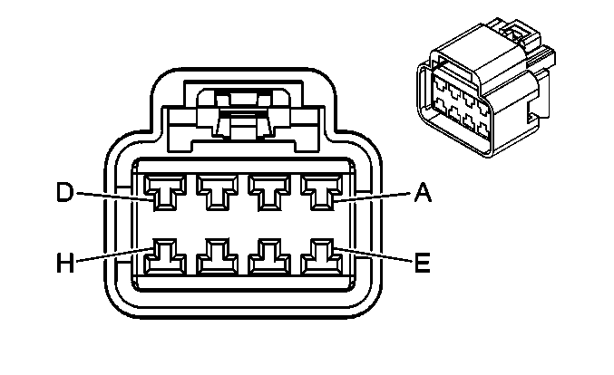
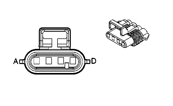
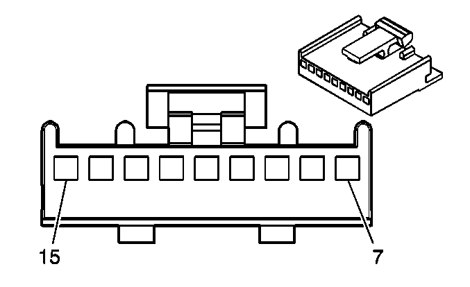
Pin | Wire Color | Circuit No. | Function | Pin | Wire Color | Circuit No. | Function | ||||||||
1A | BRN | 882 | Right Rear Wheel Speed Sensor Signal | A | BRN | 882 | Right Rear Wheel Speed Sensor Signal | ||||||||
1B | WHT | 883 | Right Rear Wheel Speed Sensor Low Reference | B | WHT | 883 | Right Rear Wheel Speed Sensor Low Reference | ||||||||
1C | BLK | 884 | Left Rear Wheel Speed Sensor Signal | C | BLK | 884 | Left Rear Wheel Speed Sensor Signal | ||||||||
1D | RED | 885 | Left Rear Wheel Speed Sensor Low Reference | D | RED | 885 | Left Rear Wheel Speed Sensor Low Reference | ||||||||
|
|
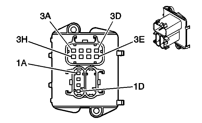
| ||||||||||||||
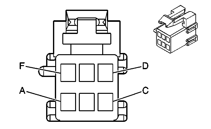
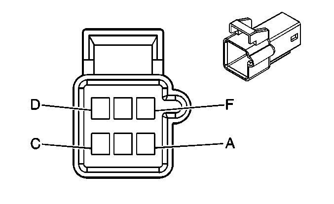
|---|---|---|---|---|---|---|---|---|---|---|---|---|---|---|---|
Connector Part Information |
| Connector Part Information |
| ||||||||||||
Pin | Wire Color | Circuit No. | Function | Pin | Wire Color | Circuit No. | Function | ||||||||
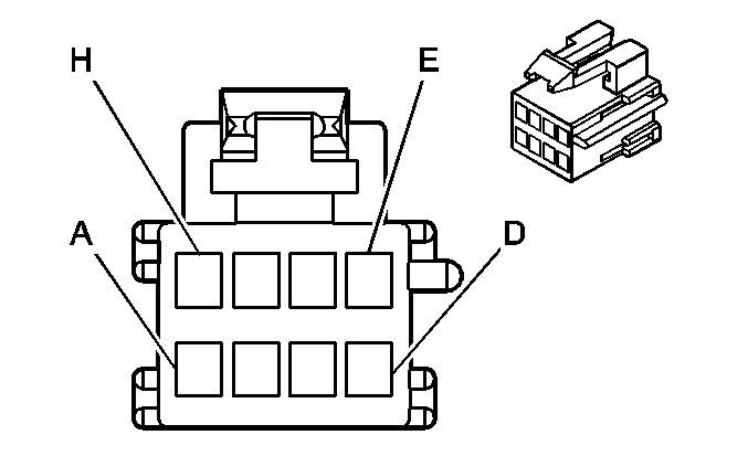
3A | BLK | 1850 | Ground | A | BLK | 1850 | Ground | ||||||||
3B | BLK | 808 | Low Reference | B | BLK/WHT | 808 | Low Reference | ||||||||
3C | GRY | 120 | Fuel Pump Supply Voltage | C | GRY | 120 | Fuel Pump Supply Voltage | ||||||||
3D | PPL | 1589 | Fuel Level Sensor Signal | D | PPL | 1589 | Fuel Level Sensor Signal | ||||||||
3E | -- | -- | Not Used | E | -- | -- | Not Used | ||||||||
3F | GRY/BLK | 2709 | 5 Volt Reference | F | GRY | 2709 | 5 Volt Reference | ||||||||
3G | DK GRN | 890 | Fuel Tank Pressure Sensor Signal | G | DK GRN | 890 | Fuel Tank Pressure Sensor Signal | ||||||||
3H | BLK | 808 | Low Reference | H | ORN/BLK | 808 | Low Reference | ||||||||
|
| ||||||||||||||
|---|---|---|---|---|---|---|---|---|---|---|---|---|---|---|---|
Connector Part Information |
| Connector Part Information |
| ||||||||||||
Pin | Wire Color | Circuit No. | Function | Pin | Wire Color | Circuit No. | Function | ||||||||
A | RED/BLK | 744 | Trunk Ajar Switch Signal | A | RED/BLK | 744 | Trunk Ajar Switch Signal | ||||||||
B | ORN | 2440 | Battery Positive Voltage | B | ORN | 2440 | Battery Positive Voltage | ||||||||
|
|
| ||||||||||||||
|---|---|---|---|---|---|---|---|---|---|---|---|---|---|---|---|
Connector Part Information |
| Connector Part Information |
| ||||||||||||
Pin | Wire Color | Circuit No. | Function | Pin | Wire Color | Circuit No. | Function | ||||||||
A | DK GRN/ WHT | 368 | Remote Radio Audio Signal | A | DK GRN/ WHT | 368 | Remote Radio Audio Signal | ||||||||
B | BLK/WHT | 372 | Remote Radio Audio Output (-) | B | BLK/WHT | 372 | Remote Radio Audio Output (-) | ||||||||
C | BARE | 814 | Drain Wire | C | BARE | 814 | Drain Wire | ||||||||
D | -- | -- | Not Used | D | -- | -- | Not Used | ||||||||
E | BLK | 550 | Ground | E | BLK | 1050 | Ground | ||||||||
F | GRY | 655 | Cellular Microphone Signal | F | GRY | 655 | Cellular Microphone Signal | ||||||||
G | DK GRN/ WHT | 2514 | Keypad Signal | G | DK GRN/ WHT | 2514 | Keypad Signal | ||||||||
H | LT GRN/BLK | 2515 | Keypad Supply Voltage | H | LT GRN/BLK | 2515 | Keypad Supply Voltage | ||||||||
J | YEL/BLK | 2516 | Keypad Green LED Signal | J | YEL/BLK | 2516 | Keypad Green LED Signal | ||||||||
K | -- | -- | Not Used | K | ORN/BLK | 2518 | Keypad Low Reference | ||||||||
L | BRN/WHT | 2517 | Keypad Red LED Signal | L | BRN/WHT | 2517 | Keypad Red LED Signal | ||||||||
M | BARE | 1705 | Drain Wire | M | BARE | 1705 | Drain Wire | ||||||||
N | PPL | 1807 | Class 2 Serial Data | N | PPL | 1807 | Class 2 Serial Data | ||||||||
P | ORN | 2540 | Battery Positive Voltage | P | ORN | 2540 | Battery Positive Voltage | ||||||||
R-S | -- | -- | Not Used | R-S | -- | -- | Not Used | ||||||||
|
| ||||||||||||||
|---|---|---|---|---|---|---|---|---|---|---|---|---|---|---|---|
Connector Part Information |
| Connector Part Information |
| ||||||||||||
Pin | Wire Color | Circuit No. | Function | Pin | Wire Color | Circuit No. | Function | ||||||||
7 | -- | -- | Not Used | 7 | -- | -- | Not Used | ||||||||
8 | BLK/WHT | 1251 | Ground | 8 | -- | -- | Not Used | ||||||||
9 | RED/BLK | 744 | Trunk Ajar Switch Signal | 9 | RED/BLK | 744 | Trunk Ajar Switch Signal | ||||||||
10 | RED/BLK | 744 | Trunk Ajar Switch Signal (w/ 9C1/9C3/9C6) | 10 | RED/BLK | 744 | Trunk Ajar Switch Signal | ||||||||
11 | ORN/BLK | 737 | Trunk Lamp Control | 11 | GRY | 2537 | Trunk Ajar Switch Signal | ||||||||
12 | PPL | 1500 | Ignition 0 Voltage | 12 | -- | -- | Not Used | ||||||||
13 | ORN | 2440 | Battery Positive Voltage | 13 | -- | -- | Not Used | ||||||||
14 | GRY | 2537 | Trunk Ajar Switch Signal | 14 | ORN/BLK | 737 | Trunk Lamp Control | ||||||||
15 | -- | -- | Not Used | 15 | -- | -- | Not Used | ||||||||
|
|
| ||||||||||||||
|---|---|---|---|---|---|---|---|---|---|---|---|---|---|---|---|
Connector Part Information |
| Connector Part Information |
| ||||||||||||
Pin | Wire Color | Circuit No. | Function | Pin | Wire Color | Circuit No. | Function | ||||||||
A | BLK | 1750 | Ground | A | BLK | 1750 | Ground | ||||||||
B | RED/BLK | 744 | Trunk Ajar Switch Signal | B | RED/BLK | 744 | Trunk Ajar Switch Signal | ||||||||
C | LT BLU | 1344 | Trunk Release Relay Control | C | LT BLU | 1344 | Trunk Release Relay Control | ||||||||
D | LT GRN | 24 | Backup Lamp Supply Voltage (Impala) | D | LT GRN | 24 | Backup Lamp Supply Voltage (Impala) | ||||||||
E | -- | -- | Not Used | E | -- | -- | Not Used | ||||||||
F | WHT | 17 | Stop Lamp Switch Signal | F | WHT | 17 | Stop Lamp Switch Signal | ||||||||
|
|
| ||||||||||||||
|---|---|---|---|---|---|---|---|---|---|---|---|---|---|---|---|
Connector Part Information |
| Connector Part Information |
| ||||||||||||
Pin | Wire Color | Circuit No. | Function | Pin | Wire Color | Circuit No. | Function | ||||||||
A | YEL | 343 | Accessory Voltage | A | YEL | 343 | Accessory Voltage | ||||||||
B | BLK | 1750 | Ground | B | BLK | 1750 | Ground | ||||||||
C | BRN | 100 | Sunroof Switch Open Signal | C | BRN | 100 | Sunroof Switch Open Signal | ||||||||
D | DK BLU | 128 | Sunroof Switch Low Reference | D | DK BLU | 128 | Sunroof Switch Low Reference | ||||||||
E | ORN | 110 | Sunroof Switch Close Signal | E | ORN | 110 | Sunroof Switch Close Signal | ||||||||
F-H | -- | -- | Not Used | F-H | -- | -- | Not Used | ||||||||
|
| ||||||||||||||
|---|---|---|---|---|---|---|---|---|---|---|---|---|---|---|---|
Connector Part Information |
| Connector Part Information |
| ||||||||||||
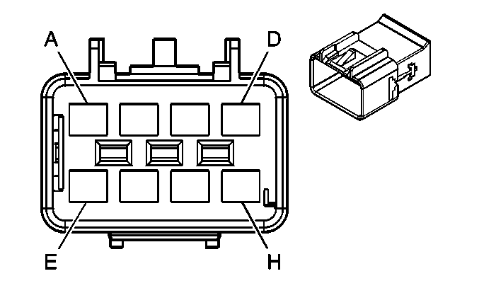
Pin | Wire Color | Circuit No. | Function | Pin | Wire Color | Circuit No. | Function | ||||||||
A | WHT | 17 | Stop Lamp Switch Signal | A | WHT | 17 | Stop Lamp Switch Signal | ||||||||
B | YEL | 18 | Left Rear Stop/Turn Lamp Supply Voltage | B | YEL | 18 | Left Rear Stop/Turn Lamp Supply Voltage | ||||||||
C | DK GRN | 19 | Right Rear Stop/Turn Lamp Supply Voltage | C | DK GRN | 19 | Right Rear Stop/Turn Lamp Supply Voltage | ||||||||
D | LT GRN | 24 | Backup Lamp Supply Voltage | D | LT GRN | 24 | Backup Lamp Supply Voltage | ||||||||
E | BLK | 1750 | Ground | E | BLK | 1750 | Ground | ||||||||
F | ORN | 340 | Battery Positive Voltage | F | ORN | 340 | Battery Positive Voltage | ||||||||
G | -- | -- | Not Used | G | LT BLU | 2624 | Emergency Vehicle Rear Lamps Supply Voltage | ||||||||
H | -- | -- | Not Used | H | -- | -- | Not Used | ||||||||
|
| ||||||||||||||
|---|---|---|---|---|---|---|---|---|---|---|---|---|---|---|---|
Connector Part Information |
| Connector Part Information |
| ||||||||||||
Pin | Wire Color | Circuit No. | Function | Pin | Wire Color | Circuit No. | Function | ||||||||
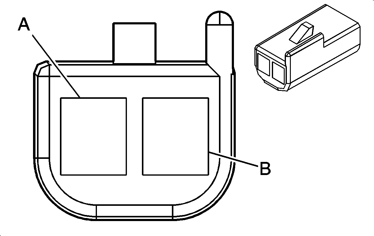
A | LT GRN | 24 | Backup Lamp Supply Voltage | A | LT GRN | 24 | Backup Lamp Supply Voltage | ||||||||
B | BLK | 1750 | Ground | B | BLK | 1750 | Ground | ||||||||
C-D | -- | -- | Not Used | C-D | -- | -- | Not Used | ||||||||
