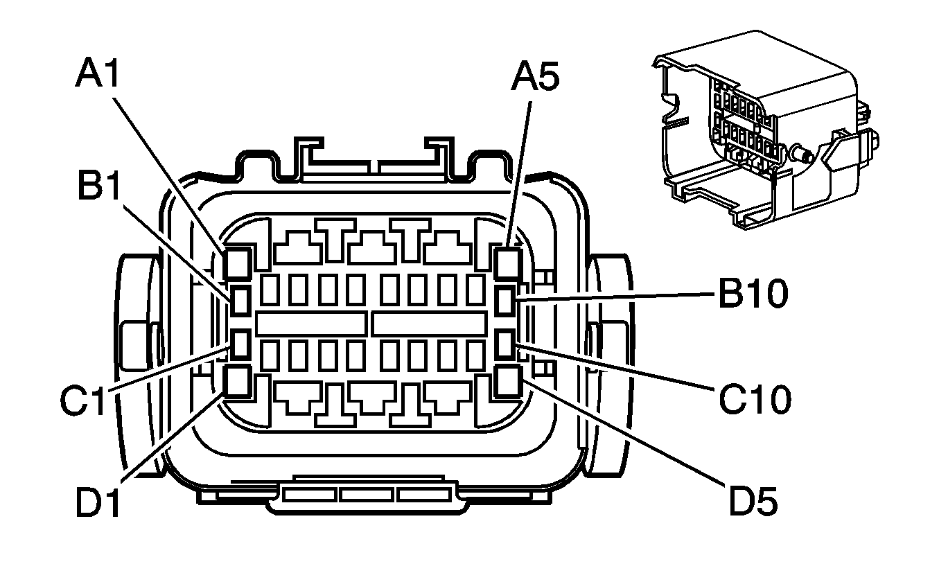
|
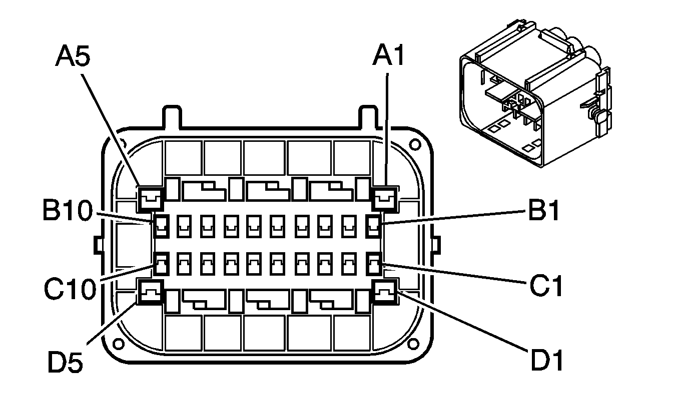
| ||||||||||||||
|---|---|---|---|---|---|---|---|---|---|---|---|---|---|---|---|
Connector Part Information |
| Connector Part Information |
| ||||||||||||
Pin | Wire Color | Circuit No. | Function | Pin | Wire Color | Circuit No. | Function | ||||||||
A1 | L-GN | 24 | Backup Lamp Supply Voltage | A1 | L-GN | 24 | Backup Lamp Supply Voltage | ||||||||
A2 | RD | 1642 | Battery Positive Voltage | A2 | RD | 1642 | Battery Positive Voltage | ||||||||
A3 | -- | -- | Not Used | A3 | -- | -- | Not Used | ||||||||
A4 | RD | 42 | Battery Positive Voltage | A4 | RD | 42 | Battery Positive Voltage | ||||||||
A5 | OG | 1840 | Battery Positive Voltage | A5 | OG | 1840 | Battery Positive Voltage | ||||||||
B1-B2 | -- | -- | Not Used | B1-B2 | -- | -- | Not Used | ||||||||
B3 | L-GN | 1478 | Coolant Level Switch Signal | B3 | L-GN | 1478 | Coolant Level Switch Signal | ||||||||
B4 | TN | 1465 | Fuel Pump Relay Control - Secondary | B4 | TN | 1465 | Fuel Pump Relay Control - Secondary (L18) | ||||||||
-- | -- | Not Used (LG4/LG5/LLY) | |||||||||||||
B5 | -- | -- | Not Used | B5 | BK | 250 | Ground (L18) | ||||||||
-- | -- | Not Used (LG4/LG5/LLY) | |||||||||||||
B6 | D-BU | 1936 | Fuel Level Sensor Signal - Secondary | B6 | D-BU | 1936 | Fuel Level Sensor Signal - Secondary | ||||||||
B7 | PU | 1589 | Fuel Level Sensor Signal - Primary | B7 | PU | 1589 | Fuel Level Sensor Signal - Primary | ||||||||
B8 | GY/BK | 1467 | Shift Motor Relay - Control (HPZ) Air Shift Switch Signal (HR1 or HR2) | B8 | GY/BK | 1467 | Shift Motor Relay - Control (HPZ) Air Shift Switch Signal (HR1 or HR2) | ||||||||
-- | -- | Not Used (w/o HPZ/HR1/HR2) | -- | -- | Not Used (w/o HPZ/HR1/HR2) | ||||||||||
B9 | BK/WH | 451 | Ground | B9 | BK/WH | 351 | Ground | ||||||||
B10 | D-GN | 29 | Horn Control | B10 | D-GN | 29 | Horn Control | ||||||||
C1 | BK/WH | 351 | Ground | C1 | BK/WH | 351 | Ground | ||||||||
C2 | YE/BK | 1827 | Vehicle Speed Signal | C2 | D-GN/WH | 817 | Vehicle Speed Signal (LG4) | ||||||||
YE/BK | 1827 | Vehicle Speed Signal (L18/LG5/LLY) | |||||||||||||
C3 | BK | 2657 | ABS Active Signal | C3 | BK | 2657 | ABS Active Signal | ||||||||
-- | -- | Not Used (L18) | |||||||||||||
C4 | BK | 470 | Low Reference | C4 | BK | 470 | Low Reference | ||||||||
C5 | YE | 2361 | SAE J1939 Serial Data Bus+ | C5 | YE | 2361 | SAE J1939 Serial Data Bus+ | ||||||||
C6 | D-GN | 2362 | SAE J1939 Serial Data Bus- | C6 | D-GN | 2362 | SAE J1939 Serial Data Bus- | ||||||||
C7 | BK | 250 | Ground | C7 | BK | 250 | Ground | ||||||||
C8 | TN | 1997 | Ether Solenoid Supply Voltage | C8 | TN | 1997 | Ether Solenoid Supply Voltage | ||||||||
C9-C10 | -- | -- | Not Used | C9-C10 | -- | -- | Not Used | ||||||||
D1 | GY | 120 | Fuel Pump Supply Voltage | D1 | GY | 120 | Fuel Pump Supply Voltage | ||||||||
D2 | RD | 2 | Battery Positive Voltage | D2 | RD | 2 | Battery Positive Voltage | ||||||||
D3 | -- | -- | Not Used | D3 | -- | -- | Not Used | ||||||||
D4 | RD | 442 | Battery Positive Voltage | D4 | RD | 442 | Battery Positive Voltage | ||||||||
D5 | -- | -- | Not Used | D5 | -- | -- | Not Used | ||||||||

|

| ||||||||||||||
|---|---|---|---|---|---|---|---|---|---|---|---|---|---|---|---|
Connector Part Information |
| Connector Part Information |
| ||||||||||||
Pin | Wire Color | Circuit No. | Function | Pin | Wire Color | Circuit No. | Function | ||||||||
A1 | PK | 639 | Ignition 1 Voltage | A1 | PK | 639 | Ignition 1 Voltage | ||||||||
A2 | RD/WH | 440 | Battery Positive Voltage (JE4) | A2 | RD/WH | 440 | Battery Positive Voltage (JE4) | ||||||||
A3 | RD | 242 | Battery Positive Voltage | A3 | RD | 242 | Battery Positive Voltage | ||||||||
A4 | PK | 439 | Ignition 1 Voltage | A4 | PK | 439 | Ignition 1 Voltage | ||||||||
A5 | PK | 239 | Ignition 1 Voltage (LLY) | A5 | PK | 239 | Ignition 1 Voltage (LLY) | ||||||||
B1 | BN/WH | 419 | MIL Control | B1 | BN/WH | 419 | MIL Control (LLY) | ||||||||
B2 | D-GN | 1433 | PNP/Clutch Start Switch Signal (C6/C7/C8) | B2 | D-GN | 1433 | PNP/Clutch Start Switch Signal (C6/C7/C8) | ||||||||
B3 | L-GN | 66 | A/C Request Signal | B3 | L-GN | 66 | A/C Request Signal | ||||||||
B4 | D-BU | 84 | Cruise Control Set/Coast Switch Signal | B4 | D-BU | 84 | Cruise Control Set/Coast Switch Signal | ||||||||
B5 | GY/BK | 87 | Cruise Control Resume/Accel Switch Signal | B5 | GY/BK | 87 | Cruise Control Resume/Accel Switch Signal | ||||||||
B6 | BN/WH | 379 | CPP Switch Signal (C6/C7/C8) | B6 | BN/WH | 379 | CPP Switch Signal (C6/C7/C8) | ||||||||
B7 | L-BU | 1320 | Stop Lamp Supply Voltage | B7 | L-BU | 1320 | Stop Lamp Supply Voltage | ||||||||
B8 | PU | 420 | TCC Brake Switch/Cruise Control Release Signal | B8 | PU | 420 | TCC Brake Switch/Cruise Control Release Signal (LLY) | ||||||||
PU | 420 | TCC Brake Switch/Cruise Control Release Signal | GY/BK | 1467 | Shift Motor Relay - Control (HPZ) Air Shift Switch Signal (HR1 or HR2) (L18) | ||||||||||
B9 | GY | 397 | Cruise Control On Switch Signal | B9 | BK/WH | 451 | Ground (L18) | ||||||||
GY | 397 | Cruise Control On Switch Signal | GY | 397 | Cruise Control On Switch Signal (LLY) | ||||||||||
B10 | PK | 239 | Ignition 1 Voltage | B10 | PK | 239 | Ignition 1 Voltage | ||||||||
C1 | GY/BK | 1467 | Shift Motor Relay - Control (C6/C7/C8 w/HPZ) | C1 | GY/BK | 1467 | Shift Motor Relay - Control (C6/C7/C8 w/HPZ) | ||||||||
C2 | BN | 441 | Ignition 3 Voltage | C2 | BN | 441 | Ignition 3 Voltage | ||||||||
C3 | D-BU | 507 | Wait to Start Indicator Control (LG4/LLY) | C3 | D-BU | 507 | Wait to Start Indicator Control (LG4/LLY) | ||||||||
C4 | PK | 1020 | Ignition 0 Voltage | C4 | PK | 1020 | Ignition 0 Voltage | ||||||||
C5 | PU | 806 | Crank Voltage (K65) | C5 | PU | 806 | Crank Voltage (K65) | ||||||||
C6 | YE | 2470 | Class 2 Serial Data (Allison® LCT) | C6 | YE | 2470 | Class 2 Serial Data (Allison® LCT) | ||||||||
C7 | BK/WH | 1962 | Exhaust Brake Actuator Control Valve Supply Voltage (K40) | C7 | BK/WH | 1962 | Exhaust Brake Actuator Control Valve Supply Voltage (K40) | ||||||||
C8 | D-GN | 1049 | ECM/PCM/VCM Class 2 Serial Data | C8 | D-GN | 1049 | ECM/PCM/VCM Class 2 Serial Data | ||||||||
C9 | BK | 28 | Ground | C9 | BK | 28 | Ground | ||||||||
C10 | BN | 641 | Ignition 3 Voltage (LLY/L18) | C10 | BN | 641 | Ignition 3 Voltage (LLY/L18) | ||||||||
D1 | D-GN/WH | 817 | Vehicle Speed Signal | D1 | D-GN/WH | 817 | Vehicle Speed Signal | ||||||||
D2 | -- | -- | Not Used | D2 | -- | -- | Not Used | ||||||||
D3 | PK | 139 | Ignition 1 Voltage | D3 | PK | 139 | Ignition 1 Voltage | ||||||||
D4 | RD/BK | 1642 | Battery Positive Voltage (C6/C7/C8) (L18) | D4 | RD/BK | 1642 | Battery Positive Voltage (C6/C7/C8) (L18) | ||||||||
D5 | L-GN | 2081 | Exhaust Brake Request Signal (K40) | D5 | L-GN | 2081 | Exhaust Brake Request Signal (K40) | ||||||||

|

| ||||||||||||||
|---|---|---|---|---|---|---|---|---|---|---|---|---|---|---|---|
Connector Part Information |
| Connector Part Information |
| ||||||||||||
Pin | Wire Color | Circuit No. | Function | Pin | Wire Color | Circuit No. | Function | ||||||||
A1 | PK | 639 | Ignition 1 Voltage | A1 | -- | -- | Not Used | ||||||||
A2 | RD/WH | 440 | Battery Positive Voltage (JE4) | A2 | RD/WH | 440 | Battery Positive Voltage | ||||||||
A3 | RD | 242 | Battery Positive Voltage | A3 | RD | 242 | Battery Positive Voltage | ||||||||
A4 | PK | 439 | Ignition 1 Voltage | A4 | PK | 439 | Ignition 1 Voltage | ||||||||
A5 | PK | 239 | Ignition 1 Voltage (LLY) | A5 | -- | -- | Not Used | ||||||||
B1 | BN/WH | 419 | MIL Control | B1 | BN/WH | 419 | MIL Control | ||||||||
B2 | D-GN | 1433 | PNP/Clutch Start Switch Signal (C6/C7/C8) | B2 | D-GN | 1433 | PNP/Clutch Start Switch Signal (Manual Transmission) | ||||||||
-- | -- | Not Used (Automatic Transmission) | |||||||||||||
B3 | L-GN | 66 | A/C Request Signal | B3 | L-GN | 66 | A/C Request Signal | ||||||||
B4 | D-BU | 84 | Cruise Control Set/Coast Switch Signal | B4 | D-BU | 84 | Cruise Control Set/Coast Switch Signal | ||||||||
B5 | GY/BK | 87 | Cruise Control Resume/Accel Switch Signal | B5 | GY/BK | 87 | Cruise Control Resume/Accel Switch Signal | ||||||||
B6 | BN/WH | 379 | CPP Switch Signal (C6/C7/C8) | B6 | BN/WH | 379 | CPP Switch Signal (Manual Transmission) | ||||||||
-- | -- | Not Used (Automatic Transmission) | |||||||||||||
B7 | L-BU | 1320 | Stop Lamp Supply Voltage | B7 | L-BU | 1320 | Stop Lamp Supply Voltage | ||||||||
B8 | BN | 25 | Charge Indicator Control/Charge Indicator Signal | B8 | BN | 25 | Charge Indicator Control/Charge Indicator Signal | ||||||||
B9 | GY | 397 | Cruise Control On Switch Signal | B9 | GY | 397 | Cruise Control On Switch Signal | ||||||||
B10 | PK | 239 | Ignition 1 Voltage | B10 | PK | 239 | Ignition 1 Voltage | ||||||||
C1-C3 | -- | -- | Not Used | C1-C3 | -- | -- | Not Used | ||||||||
C4 | PK | 1020 | Ignition 0 Voltage | C4 | PK | 1020 | Ignition 0 Voltage (Automatic Transmission) | ||||||||
-- | -- | Not Used (Manual Transmission) | |||||||||||||
C5 | BK/WH | 451 | Ground | C5 | BK/WH | 451 | Ground | ||||||||
C6 | YE | 2470 | Class 2 Serial Data (Allison® LCT) | C6 | YE | 2470 | Class 2 Serial Data (Allison® LCT) | ||||||||
-- | -- | Not Used (w/o Allison® LCT) | -- | -- | Not Used (w/o Allison® LCT) | ||||||||||
C7 | BK/WH | 1962 | Exhaust Brake Actuator Control Valve Supply Voltage (K40) | C7 | BK/WH | 1962 | Exhaust Brake Actuator Control Valve Supply Voltage (K40) | ||||||||
C8 | -- | -- | Not Used | C8 | -- | -- | Not Used | ||||||||
C9 | BK | 28 | Ground | C9 | BK | 28 | Ground | ||||||||
C10 | BK | 750 | Ground | C10 | BK | 750 | Ground | ||||||||
D1 | D-GN/WH | 817 | Vehicle Speed Signal | D1 | D-GN/WH | 817 | Vehicle Speed Signal | ||||||||
D2 | -- | -- | Not Used | D2 | -- | -- | Not Used | ||||||||
D3 | PK | 139 | Ignition 1 Voltage | D3 | PK | 139 | Ignition 1 Voltage | ||||||||
D4 | RD/BK | 1642 | Battery Positive Voltage (C6/C7/C8) (L18) | D4 | RD/BK | 1642 | Battery Positive Voltage (C6/C7/C8) (L18) | ||||||||
D5 | L-GN | 2081 | Exhaust Brake Request Signal (K40) | D5 | L-GN | 2081 | Exhaust Brake Request Signal (K40) | ||||||||
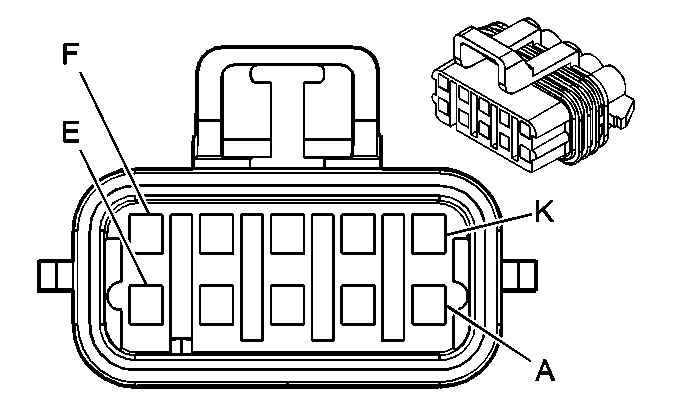
|
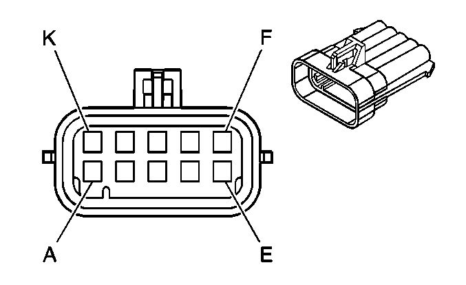
| ||||||||||||||||
|---|---|---|---|---|---|---|---|---|---|---|---|---|---|---|---|---|---|
Connector Part Information |
| Connector Part Information |
| ||||||||||||||
Pin | Wire Color | Circuit No. | Function | Pin | Wire Color | Circuit No. | Function | ||||||||||
A | PU | 1146 | Engine Brake Enable Signal (K40) | A | -- | -- | Upfitter Usage | ||||||||||
B | YE | 1479 | A/T Neutral Signal (Allison® LCT) | B | -- | -- | Upfitter Usage | ||||||||||
C | YE | 2522 | PTO Feedback (LG5/Allison® LCT) | C | -- | -- | Upfitter Usage | ||||||||||
L-BN | 915 | Right Front Turn Signal Lamp Supply Voltage (LG5/Allison® MD) | |||||||||||||||
D | -- | -- | Not Used | D | -- | -- | Upfitter Usage | ||||||||||
E | -- | -- | Not Used | E | -- | -- | Upfitter Usage | ||||||||||
F | TN | 1147 | Transmission Shift Inhibit Signal | F | -- | -- | Upfitter Usage | ||||||||||
G | -- | -- | Not Used | G | -- | -- | Upfitter Usage | ||||||||||
H | BK | 407 | Low Reference | H | -- | -- | Upfitter Usage | ||||||||||
J | -- | -- | Not Used | J | -- | -- | Upfitter Usage | ||||||||||
K | L-BU | 1480 | Transmission Power Take-Off Enable Signal | K | -- | -- | Upfitter Usage | ||||||||||
|
| ||||||||||||||
|---|---|---|---|---|---|---|---|---|---|---|---|---|---|---|---|
Connector Part Information |
| Connector Part Information |
| ||||||||||||
Pin | Wire Color | Circuit No. | Function | Pin | Wire Color | Circuit No. | Function | ||||||||
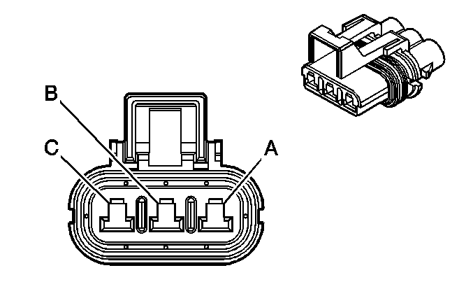
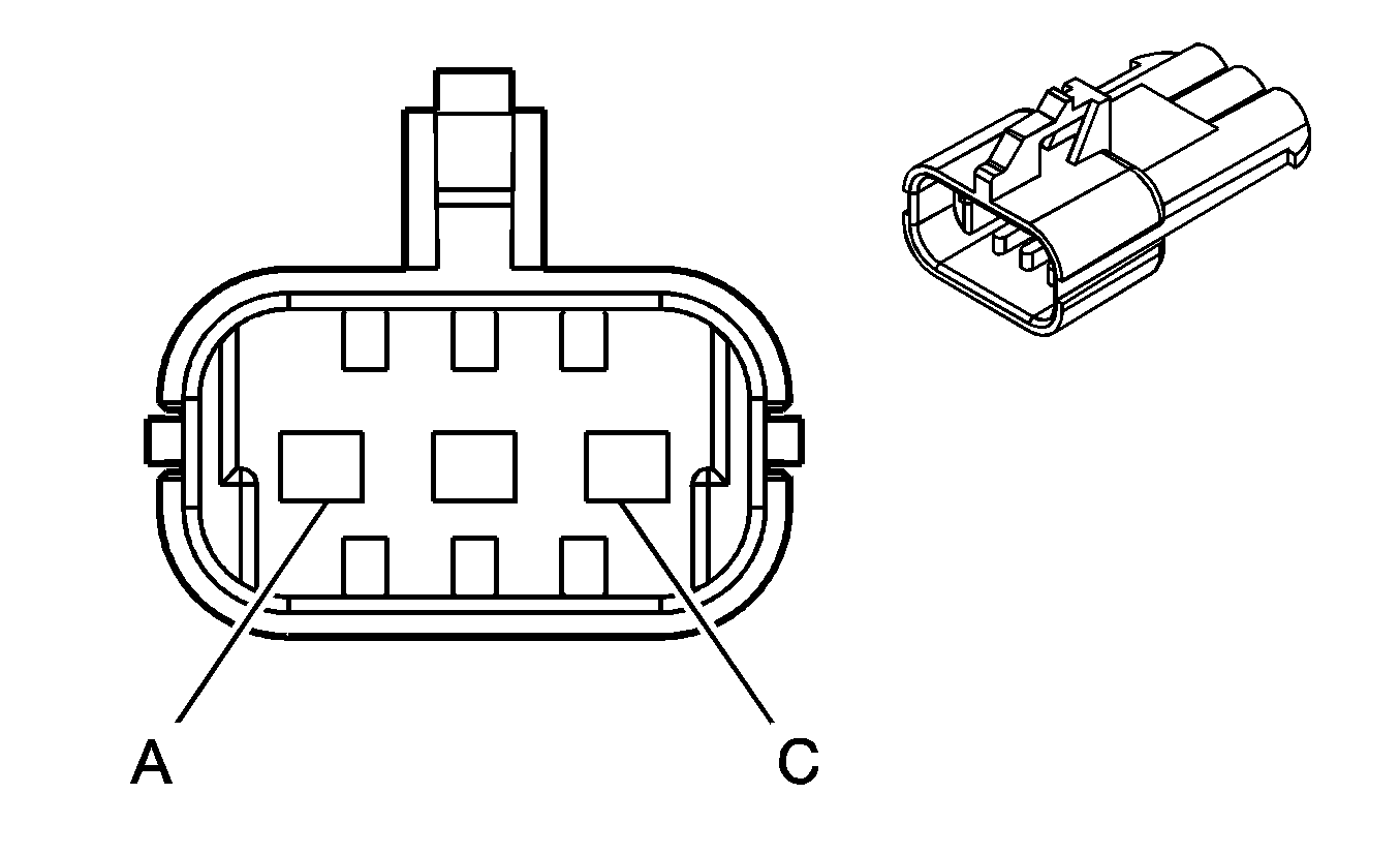
A | OG | 1840 | Battery Positive Voltage | A | -- | -- | Upfitter Usage | ||||||||
B | BN | 541 | Ignition 3 Voltage | B | -- | -- | Upfitter Usage | ||||||||
C | BK | 350 | Ground | C | -- | -- | Upfitter Usage | ||||||||
|
| ||||||||||||||
|---|---|---|---|---|---|---|---|---|---|---|---|---|---|---|---|
Connector Part Information |
| Connector Part Information |
| ||||||||||||
Pin | Wire Color | Circuit No. | Function | Pin | Wire Color | Circuit No. | Function | ||||||||
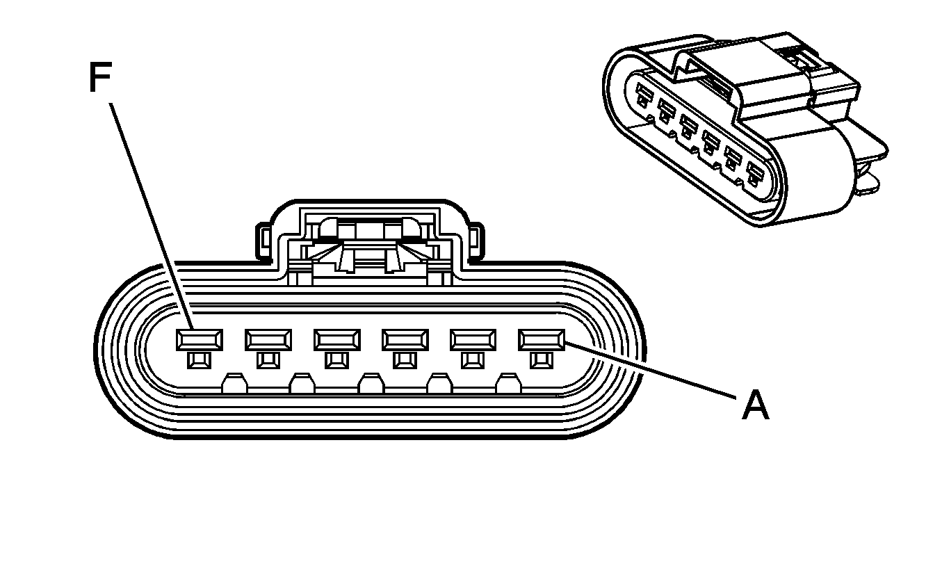
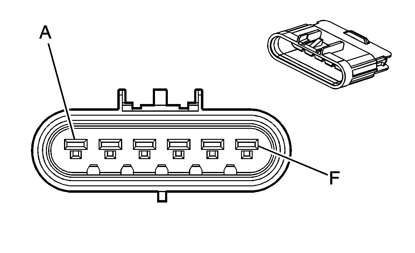
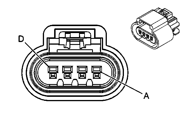
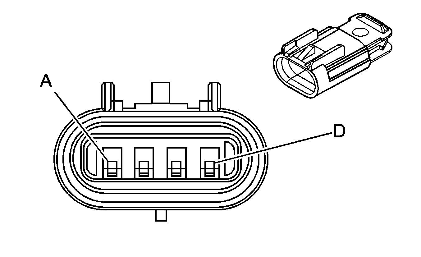
A | BK | 250 | Ground | A | BK | 250 | Ground | ||||||||
B | PK | 339 | Ignition 1 Voltage | B | PK | 339 | Ignition 1 Voltage | ||||||||
C | PU | 2656 | Exhaust Brake Control | C | PU | 2656 | Exhaust Brake Control | ||||||||
D | BK | 2657 | ABS Active Signal | D | BK | 2657 | ABS Active Signal | ||||||||
E | BK/WH | 1962 | Engine Brake Solenoid - Feed (LG4/LG5) | E | BK/WH | 1962 | Engine Brake Solenoid - Feed (LG4/LG5) | ||||||||
-- | -- | Not Used (LLY) | -- | -- | Not Used (LLY) | ||||||||||
F | -- | -- | Not Used | F | -- | -- | Not Used | ||||||||
|
| ||||||||||||||
|---|---|---|---|---|---|---|---|---|---|---|---|---|---|---|---|
Connector Part Information |
| Connector Part Information |
| ||||||||||||
Pin | Wire Color | Circuit No. | Function | Pin | Wire Color | Circuit No. | Function | ||||||||
A | L-GN | 66 | A/C Request Signal | A | L-GN | 66 | A/C Request Signal | ||||||||
B | OG | 1240 | Battery Positive Voltage | B | OG | 1240 | Battery Positive Voltage | ||||||||
C | BK | 250 | Ground | C | BK | 250 | Ground | ||||||||
D | D-GN/WH | 459 | A/C Compressor Clutch Relay Control | D | D-GN/WH | 459 | A/C Compressor Clutch Relay Control | ||||||||
|
| ||||||||||||||
|---|---|---|---|---|---|---|---|---|---|---|---|---|---|---|---|
Connector Part Information |
| Connector Part Information |
| ||||||||||||
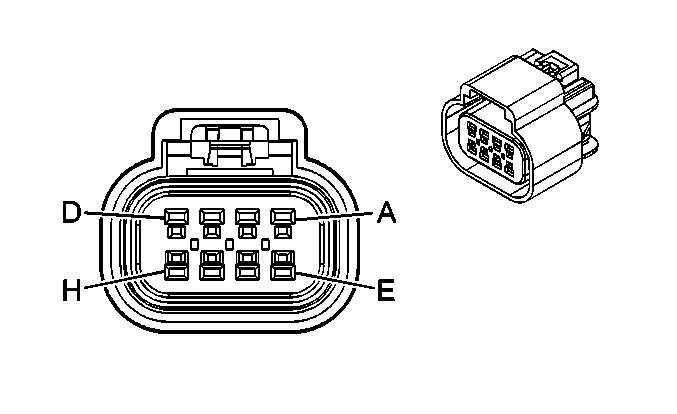
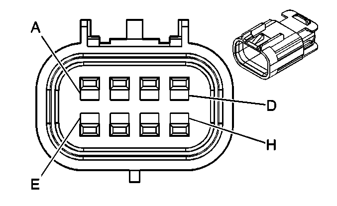
Pin | Wire Color | Circuit No. | Function | Pin | Wire Color | Circuit No. | Function | ||||||||
A | D-GN/WH | 762 | A/C Request Signal | A | D-GN/WH | 762 | A/C Request Signal | ||||||||
B | OG | 1240 | Battery Positive Voltage | B | OG | 1240 | Battery Positive Voltage | ||||||||
C | D-GN | 603 | A/C Low Pressure Switch Signal | C | D-GN | 603 | A/C Low Pressure Switch Signal | ||||||||
D | -- | -- | Not Used | D | -- | -- | Not Used | ||||||||
E | BN | 441 | Ignition 3 Voltage | E | BN | 441 | Ignition 3 Voltage | ||||||||
F | L-GN | 66 | A/C Request Signal | F | L-GN | 66 | A/C Request Signal | ||||||||
G | BK | 250 | Ground | G | BK | 250 | Ground | ||||||||
H | D-GN/WH | 459 | A/C Compressor Clutch Relay Control | H | D-GN/WH | 459 | A/C Compressor Clutch Relay Control | ||||||||

|

| ||||||||||||||
|---|---|---|---|---|---|---|---|---|---|---|---|---|---|---|---|
Connector Part Information |
| Connector Part Information |
| ||||||||||||
Pin | Wire Color | Circuit No. | Function | Pin | Wire Color | Circuit No. | Function | ||||||||
A | BK | 350 | Ground | A | BK | 350 | Ground | ||||||||
B | BN | 141 | Ignition 3 Voltage | B | BN | 141 | Ignition 3 Voltage | ||||||||
C | BK/WH | 351 | Ground | C | BK/WH | 351 | Ground | ||||||||
D | TN/WH | 585 | Transmission Oil Temperature Sensor Signal | D | TN/WH | 585 | Transmission Oil Temperature Sensor Signal | ||||||||
E | BK/WH | 451 | Ground | E | BK/WH | 451 | Ground | ||||||||
F | L-GN | 1478 | Coolant Level Switch Signal | F | L-GN | 1478 | Coolant Level Switch Signal | ||||||||
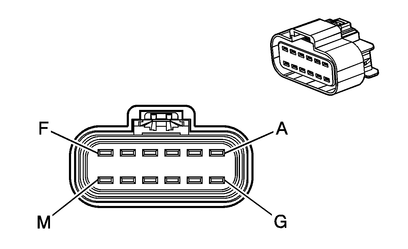
|
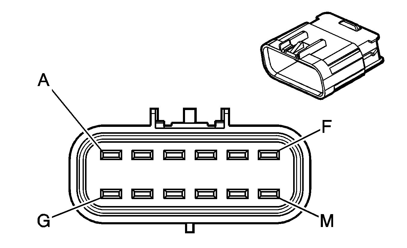
| ||||||||||||||
|---|---|---|---|---|---|---|---|---|---|---|---|---|---|---|---|
Connector Part Information |
| Connector Part Information |
| ||||||||||||
Pin | Wire Color | Circuit No. | Function | Pin | Wire Color | Circuit No. | Function | ||||||||
A | BK | 350 | Ground | A | BK | 350 | Ground | ||||||||
B | GY | 2365 | Low Reference | B | GY | 2365 | Low Reference | ||||||||
C | D-BU | 2364 | Cooling Fan Speed Signal | C | D-BU | 2364 | Cooling Fan Speed Signal | ||||||||
D | PU | 719 | Low Reference | D | PU | 719 | Low Reference | ||||||||
E | BK | 450 | Ground | E | BK | 450 | Ground | ||||||||
F | BN | 141 | Ignition 3 Voltage | F | BN | 141 | Ignition 3 Voltage | ||||||||
G | BK/WH | 351 | Ground | G | BK/WH | 351 | Ground | ||||||||
H | TN/WH | 585 | Transmission Oil Temperature Sensor Signal | H | TN/WH | 585 | Transmission Oil Temperature Sensor Signal | ||||||||
J | BK/WH | 451 | Ground | J | BK/WH | 451 | Ground | ||||||||
K | TN | 1997 | Ether Solenoid - Feed | K | -- | -- | Not Used | ||||||||
L | L-GN | 1478 | Coolant Level Switch Signal | L | L-GN | 1478 | Coolant Level Switch Signal | ||||||||
M | BK/WH | 1120 | Cooling Fan Clutch Control | M | BK/WH | 1120 | Cooling Fan Clutch Control | ||||||||
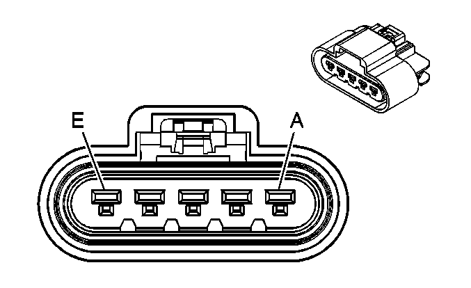
|
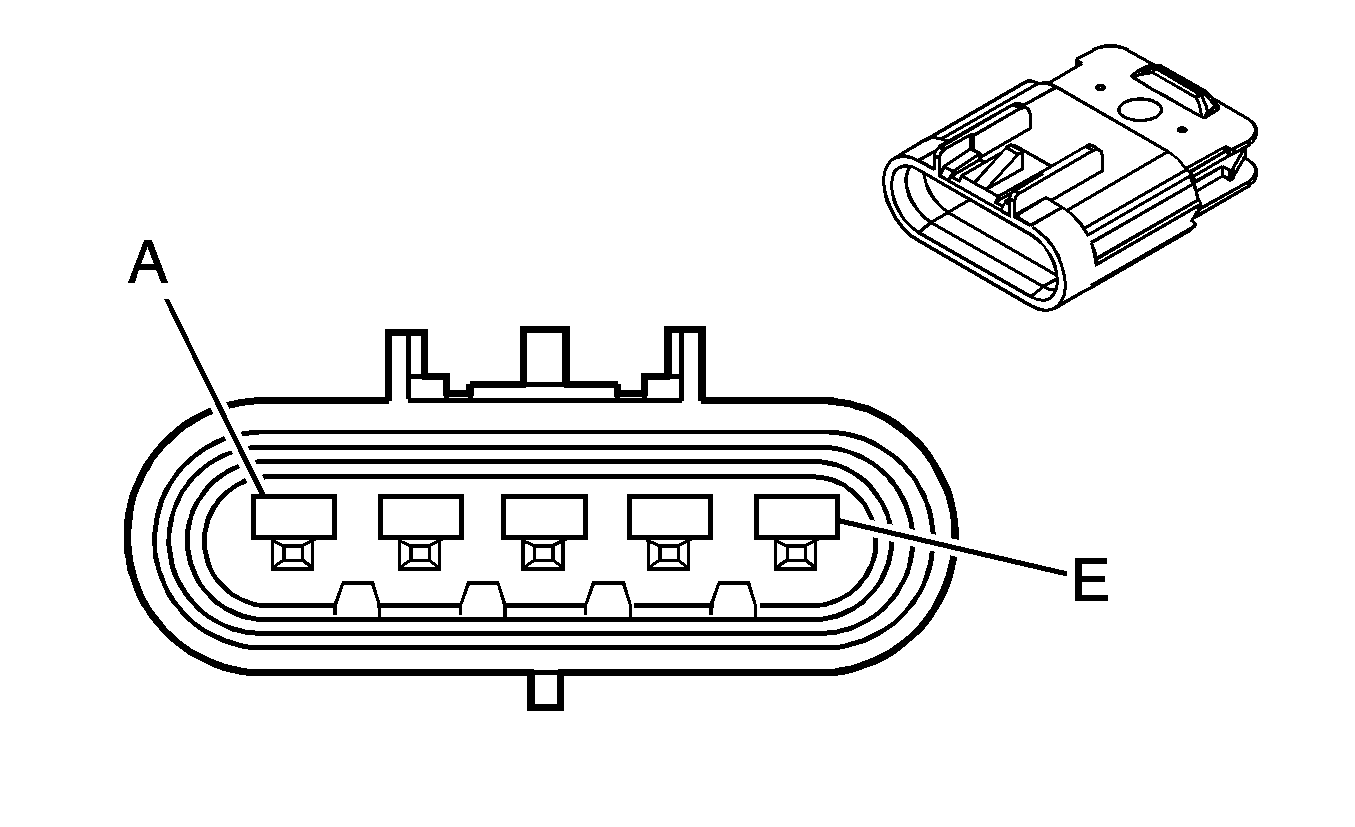
| ||||||||||||||
|---|---|---|---|---|---|---|---|---|---|---|---|---|---|---|---|
Connector Part Information |
| Connector Part Information |
| ||||||||||||
Pin | Wire Color | Circuit No. | Function | Pin | Wire Color | Circuit No. | Function | ||||||||
A | L-GN | 11 | Headlamp High Beam Supply Voltage | A | L-GN | 11 | Headlamp High Beam Supply Voltage | ||||||||
B | TN | 12 | Headlamp Low Beam Supply Voltage | B | TN | 12 | Headlamp Low Beam Supply Voltage | ||||||||
C | BK | 350 | Ground | C | BK | 350 | Ground | ||||||||
D | L-BU | 14 | Left Turn Signal Lamps Supply Voltage | D | L-BU | 14 | Left Turn Signal Lamps Supply Voltage | ||||||||
E | BN | 2509 | Left Rear Park Lamps Supply Voltage | E | BN | 2509 | Left Rear Park Lamps Supply Voltage | ||||||||

|

| ||||||||||||||
|---|---|---|---|---|---|---|---|---|---|---|---|---|---|---|---|
Connector Part Information |
| Connector Part Information |
| ||||||||||||
Pin | Wire Color | Circuit No. | Function | Pin | Wire Color | Circuit No. | Function | ||||||||
A | L-GN | 11 | Headlamp High Beam Supply Voltage | A | L-GN | 11 | Headlamp High Beam Supply Voltage | ||||||||
B | TN | 12 | Headlamp Low Beam Supply Voltage | B | TN | 12 | Headlamp Low Beam Supply Voltage | ||||||||
C | BK | 350 | Ground | C | BK | 350 | Ground | ||||||||
D | D-BU | 15 | Right Turn Signal Lamps Supply Voltage | D | L-BU | 15 | Right Turn Signal Lamps Supply Voltage | ||||||||
E | BN/WH | 2609 | Park Lamps Supply Voltage | E | BN | 2609 | Park Lamps Supply Voltage | ||||||||
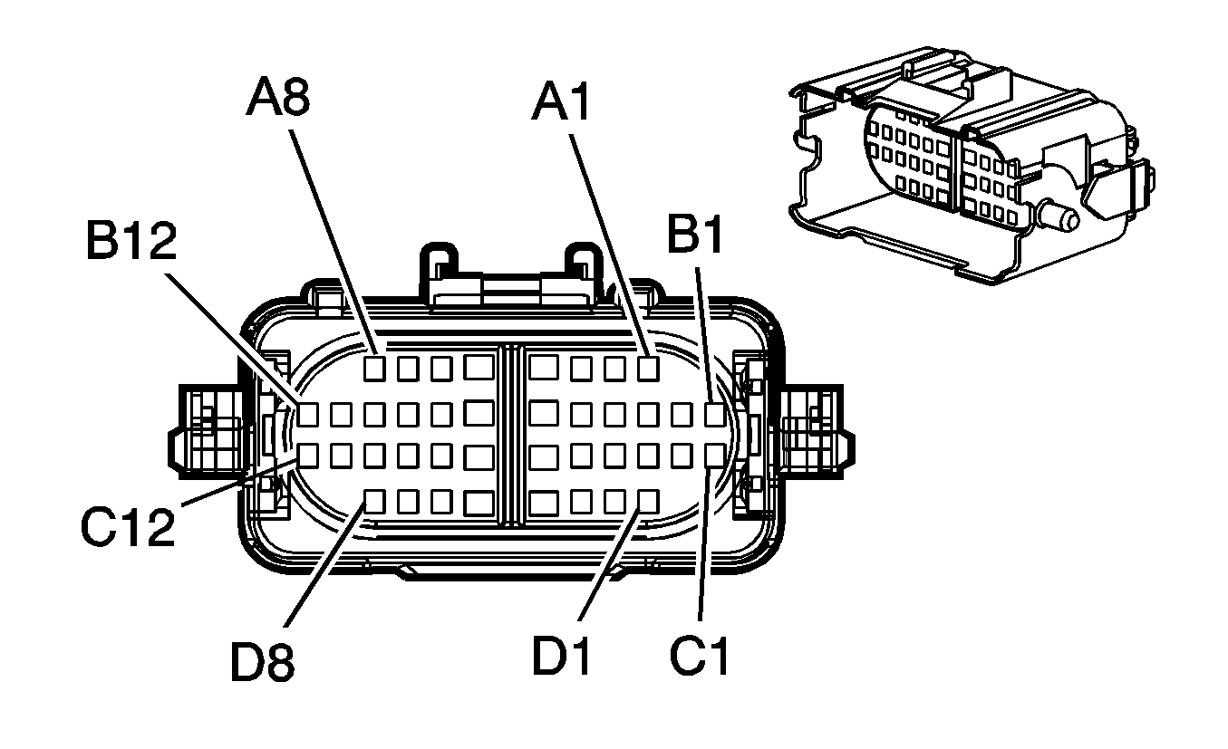
|
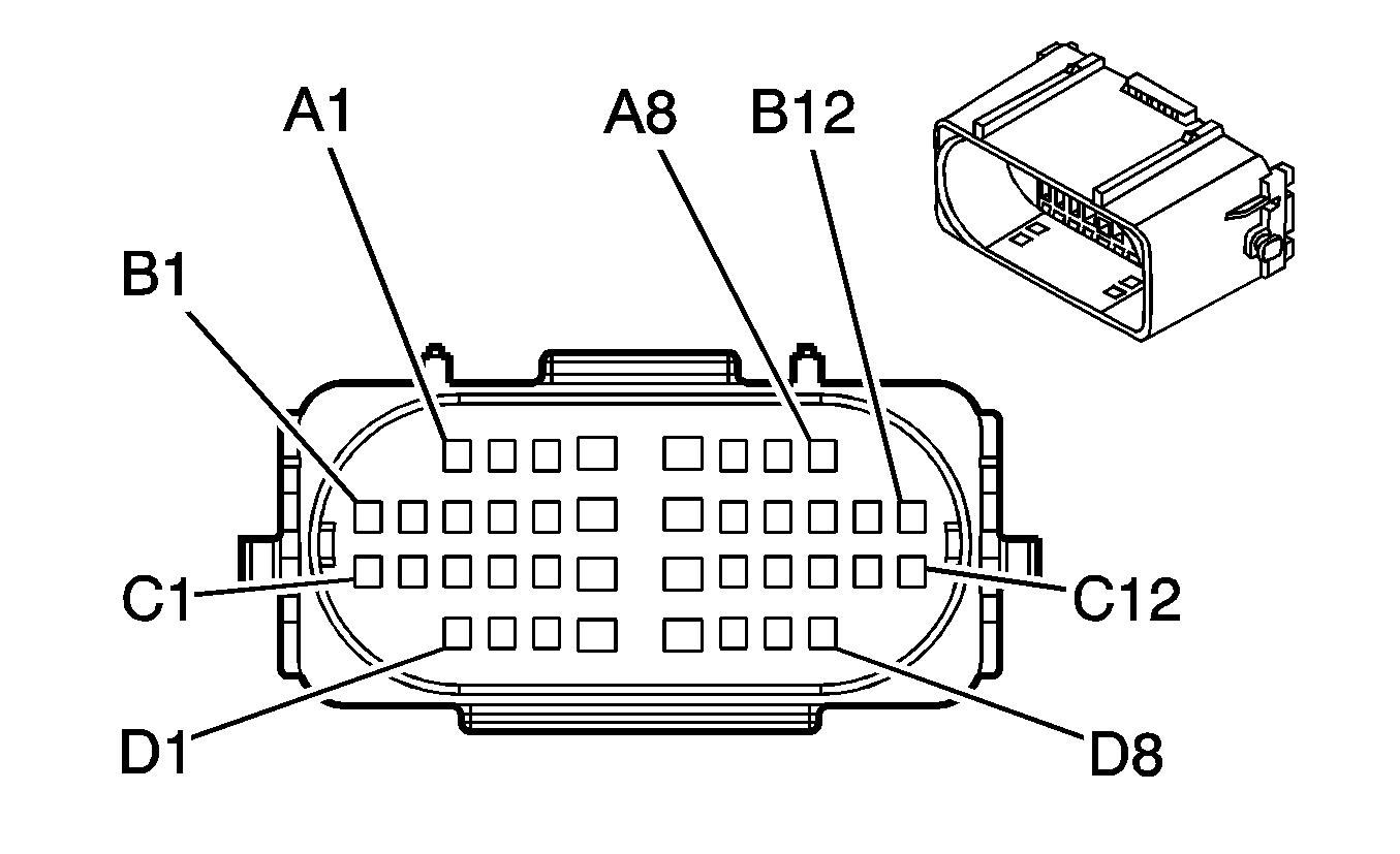
| ||||||||||||||
|---|---|---|---|---|---|---|---|---|---|---|---|---|---|---|---|
Connector Part Information |
| Connector Part Information |
| ||||||||||||
Pin | Wire Color | Circuit No. | Function | Pin | Wire Color | Circuit No. | Function | ||||||||
A1 | WH | 776 | Transmission Range Switch Signal-Pariety Bit (w/MD Transmission) | A1 | WH | 776 | Transmission Range Switch Signal-Pariety Bit (w/MD Transmission) | ||||||||
A2 | OG | 1940 | Battery Positive Voltage (w/MD Transmission) | A2 | OG | 1940 | Battery Positive Voltage (w/MD Transmission) | ||||||||
A3 | GY | 598 | 5-Volt Reference (w/MD Transmission) | A3 | GY | 598 | 5-Volt Reference (w/MD Transmission) | ||||||||
A4 | D-BU | 1378 | Transmission Shift Selector Display Signal (w/MD Transmission) | A4 | D-BU | 1378 | Transmission Shift Selector Display Signal (w/MD Transmission) | ||||||||
A5 | D-GN | 1373 | Transmission Shift Selector Mode Signal (w/MD Transmission) | A5 | D-GN | 1373 | Transmission Shift Selector Mode Signal (w/MD Transmission) | ||||||||
A6 | L-BU | 553 | Tow/Haul Switch Signal (w/MD Transmission) | A6 | L-BU | 553 | Tow/Haul Switch Signal (w/MD Transmission) | ||||||||
A7 | TN | 2654 | Shift Data (w/MD Transmission) | A7 | TN | 2654 | Shift Data (w/MD Transmission) | ||||||||
A8 | D-BU | 1161 | APP Sensor 1 Signal | A8 | D-BU | 1161 | APP Sensor 1 Signal | ||||||||
B1 | L-GN | 488 | PTO On Switch - Signal | B1 | L-GN | 488 | PTO On Switch - Signal | ||||||||
B2 | TN/BK | 1921 | SAE J1587 Serial Data Bus+ Primary (w/MD Transmission) | B2 | TN/BK | 1921 | SAE J1587 Serial Data Bus+ Primary (w/MD Transmission) | ||||||||
B3 | WH/BK | 1164 | 5-Volt Reference | B3 | WH/BK | 1164 | 5-Volt Reference | ||||||||
B4 | BK/WH | 771 | Transmission Range Switch Signal A (w/MD Transmission) | B4 | BK/WH | 771 | Transmission Range Switch Signal A (w/MD Transmission) | ||||||||
B5 | YE | 2655 | Ignition Sensor Signal (w/MD Transmission) | B5 | YE | 2655 | Ignition Sensor Signal (w/MD Transmission) | ||||||||
B6 | YE | 772 | Transmission Range Switch Signal B (w/MD Transmission) | B6 | YE | 772 | Transmission Range Switch Signal B (w/MD Transmission) | ||||||||
B7 | L-GN | 1371 | Transmission Switch Signal (w/MD Transmission) | B7 | L-GN | 1371 | Transmission Switch Signal (w/MD Transmission) | ||||||||
B8 | WH | 121 | Engine Speed Signal | B8 | WH | 121 | Engine Speed Signal | ||||||||
B9 | GY | 1234 | Do Not Shift Indicator Control (Automatic Transmission) | B9 | GY | 1234 | Do Not Shift Indicator Control (Automatic Transmission) | ||||||||
B10 | PK | 539 | Ignition 1 Voltage (LG4) | B10 | PK | 539 | Ignition 1 Voltage (LG4) | ||||||||
B11 | BN | 86 | Cruise Control Release Signal (LG5) | B11 | BN | 86 | Cruise Control Release Signal (LG5) | ||||||||
B12 | GY/BK | 1467 | Shift Motor Relay - Control (HPZ and A/T) | B12 | GY/BK | 1467 | Shift Motor Relay - Control (HPZ and A/T) | ||||||||
GY/BK | 1467 | Air Shift Switch Signal (A/T and HR1 or A/T and HR2 ) | GY/BK | 1467 | Air Shift Switch Signal (A/T and HR1 or A/T and HR2 ) | ||||||||||
C1 | -- | -- | Not Used | C1 | -- | -- | Not Used | ||||||||
C2 | WH/BK | 1922 | SAE J1587 Serial Data Bus - Primary (w/MD Transmission) | C2 | WH/BK | 1922 | SAE J1587 Serial Data Bus - Primary (w/MD Transmission) | ||||||||
C3 | L-GN | 488 | PTO On Switch Signal | C3 | L-GN | 488 | PTO On Switch Signal | ||||||||
C4 | D-GN | 534 | High Idle Switch Signal | C4 | D-GN | 534 | High Idle Switch Signal | ||||||||
C5 | RD | 2013 | High Idle Indicator Control | C5 | RD | 2013 | High Idle Indicator Control | ||||||||
C6 | L-BU | 1998 | Intake Air Heater Indicator Control (LG5) | C6 | L-BU | 1998 | Intake Air Heater Indicator Control (LG5) | ||||||||
C7 | PU | 1093 | Rear Defog Element Supply Voltage | C7 | PU | 1093 | Rear Defog Element Supply Voltage | ||||||||
C8 | YE | 2361 | SAE J1939 Serial Data Bus+ | C8 | YE | 2361 | SAE J1939 Serial Data Bus+ | ||||||||
C9 | D-GN | 2362 | SAE J1939 Serial Data Bus- | C9 | D-GN | 2362 | SAE J1939 Serial Data Bus- | ||||||||
C10 | WH | 2561 | PTO Supply Voltage (LG4 w/PTO) | C10 | WH | 2561 | PTO Supply Voltage (LG4 w/PTO) | ||||||||
C11 | PU | 2562 | PTO Control (LG4 w/PTO) | C11 | PU | 2562 | PTO Control (LG4 w/PTO) | ||||||||
C12 | TN/WH | 2678 | Overdrive Defeat Switch Signal (w/LCT Transmission) | C12 | TN/WH | 2678 | Overdrive Defeat Switch Signal (w/LCT Transmission) | ||||||||
D1 | PU | 806 | Crank Voltage | D1 | PU | 806 | Crank Voltage | ||||||||
D2 | BN | 1271 | Low Reference (LG4) | D2 | BN | 1271 | Low Reference (LG4) | ||||||||
YE/BK | 508 | Water In Fuel Indicator Control (LG5) | YE/BK | 508 | Water In Fuel Indicator Control (LG5) | ||||||||||
D3 | PU | 1272 | Low Reference (LG4) | D3 | PU | 1272 | Low Reference (LG4) | ||||||||
D4 | L-BU | 1162 | APP Sensor 2 Signal (LG4) | D4 | L-BU | 1162 | APP Sensor 2 Signal (LG4) | ||||||||
D5 | TN | 1274 | 5-Volt Reference (LG4) | D5 | TN | 1274 | 5-Volt Reference (LG4) | ||||||||
D6 | GY | 1273 | Low Reference (LG4) | D6 | GY | 1273 | Low Reference (LG4) | ||||||||
D7 | YE/BK | 1275 | 5-Volt Reference (LG4) | D7 | YE/BK | 1275 | 5-Volt Reference (LG4) | ||||||||
D8 | D-GN | 1163 | APP Sensor 3 Signal (LG4) | D8 | D-GN | 1163 | APP Sensor 3 Signal (LG4) | ||||||||

|

| ||||||||||||||
|---|---|---|---|---|---|---|---|---|---|---|---|---|---|---|---|
Connector Part Information |
| Connector Part Information |
| ||||||||||||
Pin | Wire Color | Circuit No. | Function | Pin | Wire Color | Circuit No. | Function | ||||||||
A1 | WH | 776 | Transmission Range Switch Signal-Pariety Bit | A1 | WH | 776 | Transmission Range Switch Signal-Pariety Bit | ||||||||
BK/WH | 1120 | Battery Positive Voltage | BK/WH | 1120 | Battery Positive Voltage | ||||||||||
A2 | OG | 1940 | Battery Positive Voltage | A2 | OG | 1940 | Battery Positive Voltage | ||||||||
BK/WH | 1962 | Engine Brake Solenoid - Feed | BK/WH | 1962 | Engine Brake Solenoid - Feed | ||||||||||
A3 | GY | 598 | 5-Volt Reference | A3 | GY | 598 | 5-Volt Reference | ||||||||
L-BU | 553 | Tow/Haul Switch Signal | L-BU | 553 | Tow/Haul Switch Signal | ||||||||||
A4 | D-BU | 1378 | Transmission Shift Selector Display Signal | A4 | D-BU | 1378 | Transmission Shift Selector Display Signal | ||||||||
TN/BK | 1921 | SAE J1587 Serial Data Bus+ Primary | TN/BK | 1921 | SAE J1587 Serial Data Bus+ Primary | ||||||||||
A5 | D-GN | 1373 | Transmission Shift Selector Mode Signal | A5 | D-GN | 1373 | Transmission Shift Selector Mode Signal | ||||||||
L-GN | 24 | Backup Lamp Supply Voltage | L-GN | 24 | Backup Lamp Supply Voltage | ||||||||||
A6 | L-BU | 553 | Tow/Haul Switch Signal | A6 | L-BU | 553 | Tow/Haul Switch Signal | ||||||||
D-GN | 1373 | Transmission Shift Selector Mode Signal | D-GN | 1373 | Transmission Shift Selector Mode Signal | ||||||||||
A7 | TN | 2654 | Shift Data | A7 | TN | 2654 | Shift Data | ||||||||
GY/BK | 1467 | Shift Motor Relay - Control (HPZ) | GY/BK | 1467 | Shift Motor Relay - Control (HPZ) | ||||||||||
GY/BK | 1467 | Air Shift Switch Signal (HR1 or HR2) | GY/BK | 1467 | Air Shift Switch Signal (HR1 or HR2) | ||||||||||
A8 | D-BU | 1161 | APP Sensor 1 Signal | A8 | D-BU | 1161 | APP Sensor 1 Signal | ||||||||
YE | 447 | Starter Relay Coil Control | YE | 447 | Starter Relay Coil Control | ||||||||||
B1 | -- | -- | Not Used | B1 | -- | -- | Not Used | ||||||||
BK | 470 | Low Reference | BK | 470 | Low Reference | ||||||||||
B2 | TN/BK | 1921 | SAE J1587 Serial Data Bus+ Primary | B2 | TN/BK | 1921 | SAE J1587 Serial Data Bus+ Primary | ||||||||
OG | 1940 | Battery Positive Voltage | OG | 1940 | Battery Positive Voltage | ||||||||||
B3 | WH/BK | 1164 | 5-Volt Reference | B3 | WH/BK | 1164 | 5-Volt Reference | ||||||||
L-BU | 2221 | Signal High - Rear | L-BU | 2221 | Signal High - Rear | ||||||||||
B4 | BK/WH | 771 | Transmission Range Switch Signal A | B4 | BK/WH | 771 | Transmission Range Switch Signal A | ||||||||
WH/BK | 1922 | SAE J1587 Serial Data Bus- Primary | WH/BK | 1922 | SAE J1587 Serial Data Bus- Primary | ||||||||||
B5 | YE | 2655 | Ignition Sensor Signal MWF LG5 | B5 | YE | 2655 | Ignition Sensor Signal MWF LG5 | ||||||||
PU | 2656 | Exhaust Brake Control | PU | 2656 | Exhaust Brake Control | ||||||||||
B6 | YE | 772 | Transmission Range Switch Signal B | B6 | YE | 772 | Transmission Range Switch Signal B | ||||||||
L-BU | 494 | Engine Shut-Off Signal | L-BU | 494 | Engine Shut-Off Signal | ||||||||||
B7 | L-GN | 1371 | Transmission Position Switch - Signal - Bit 4 | B7 | L-GN | 1371 | Transmission Position Switch - Signal - Bit 4 | ||||||||
YE/BK | 1827 | Vehicle Speed Signal | YE/BK | 1827 | Vehicle Speed Signal | ||||||||||
B8 | WH | 121 | Engine Speed Signal | B8 | WH | 121 | Engine Speed Signal | ||||||||
WH | 776 | Transmission Range Switch Signal-Pariety Bit | WH | 776 | Transmission Range Switch Signal-Pariety Bit | ||||||||||
B9 | GY | 1234 | Do Not Shift Indicator Control | B9 | GY | 1234 | Do Not Shift Indicator Control | ||||||||
L-GN | 488 | PTO On Switch Signal | L-GN | 488 | PTO On Switch Signal | ||||||||||
B10 | -- | -- | Not Used | B10 | -- | -- | Not Used | ||||||||
TN/WH | 2678 | Overdrive Defeat Switch Signal | TN/WH | 2678 | Overdrive Defeat Switch Signal | ||||||||||
B11 | BN | 86 | Cruise Control Release Signal | B11 | BN | 86 | Cruise Control Release Signal | ||||||||
GY | 23 | Engine Coolant Temperature Sensor Signal | GY | 23 | Engine Coolant Temperature Sensor Signal | ||||||||||
B12 | GY/BK | 1467 | Shift Motor Relay - Control (HPZ) | B12 | GY/BK | 1467 | Shift Motor Relay - Control (HPZ) | ||||||||
GY/BK | 1467 | Air Shift Switch Signal (HR1 or HR2) | GY/BK | 1467 | Air Shift Switch Signal (HR1 or HR2) | ||||||||||
BN | 25 | Charge Indicator Control/Charge Indicator Signal | BN | 25 | Charge Indicator Control/Charge Indicator Signal | ||||||||||
C1 | -- | -- | Not Used | C1 | -- | -- | Not Used | ||||||||
PU | 2562 | PTO Control | PU | 2562 | PTO Control | ||||||||||
C2 | WH/BK | 1922 | SAE J1708 Serial Data B | C2 | WH/BK | 1922 | SAE J1708 Serial Data B | ||||||||
GY/BK | 1467 | Shift Motor Relay - Control (HPZ) | GY/BK | 1467 | Shift Motor Relay - Control (HPZ) | ||||||||||
GY/BK | 1467 | Air Shift Switch Signal (HR1 or HR2) | GY/BK | 1467 | Air Shift Switch Signal (HR1 or HR2) | ||||||||||
C3 | L-GN | 488 | PTO On Switch Signal | C3 | L-GN | 488 | PTO On Switch Signal | ||||||||
YE | 2655 | Ignition Sensor Signal | YE | 2655 | Ignition Sensor Signal | ||||||||||
C4 | D-GN | 534 | High Idle Switch Signal | C4 | D-GN | 534 | High Idle Switch Signal | ||||||||
PU | 1589 | Fuel Level Sensor Signal - Primary | PU | 1589 | Fuel Level Sensor Signal - Primary | ||||||||||
C5 | RD | 2013 | High Idle Indicator Control | C5 | RD | 2013 | High Idle Indicator Control | ||||||||
D-BU | 1936 | Fuel Level Sensor Signal - Secondary | D-BU | 1936 | Fuel Level Sensor Signal - Secondary | ||||||||||
C6 | L-BU | 1998 | Intake Air Heater Indicator Control | C6 | L-BU | 1998 | Intake Air Heater Indicator Control | ||||||||
PU | 1093 | Rear Defog Element Supply Voltage | PU | 1093 | Rear Defog Element Supply Voltage | ||||||||||
C7 | PU | 1093 | Rear Defog Element Supply Voltage | C7 | PU | 1093 | Rear Defog Element Supply Voltage | ||||||||
D-BU | 1378 | Transmission Shift Selector Display Signal | D-BU | 1378 | Transmission Shift Selector Display Signal | ||||||||||
C8 | YE | 2361 | SAE J1939 Serial Data Bus+ | C8 | YE | 2361 | SAE J1939 Serial Data Bus+ | ||||||||
D-GN/WH | 459 | A/C Compressor Clutch Relay Control | D-GN/WH | 459 | A/C Compressor Clutch Relay Control | ||||||||||
C9 | D-GN | 2362 | SAE J1939 Serial Data Bus- | C9 | D-GN | 2362 | SAE J1939 Serial Data Bus- | ||||||||
BK/WH | 771 | Transmission Range Switch Signal A | BK/WH | 771 | Transmission Range Switch Signal A | ||||||||||
C10 | -- | -- | Not Used | C10 | -- | -- | Not Used | ||||||||
TN | 2654 | Shift Data | TN | 2654 | Shift Data | ||||||||||
C11 | -- | -- | Not Used | C11 | -- | -- | Not Used | ||||||||
YE | 505 | Glow Plug Relay Control | YE | 505 | Glow Plug Relay Control | ||||||||||
C12 | TN/WH | 2678 | Overdrive Defeat Switch Signal | C12 | TN/WH | 2678 | Overdrive Defeat Switch Signal | ||||||||
D-GN | 2222 | Signal Low - Rear | D-GN | 2222 | Signal Low - Rear | ||||||||||
D1 | PU | 806 | Crank Voltage | D1 | PU | 806 | Crank Voltage | ||||||||
YE | 2522 | PTO Engage Signal | YE | 2522 | PTO Engage Signal | ||||||||||
D2 | YE/BK | 508 | Water In Fuel Indicator Control | D2 | YE/BK | 508 | Water In Fuel Indicator Control | ||||||||
L-GN | 1478 | Coolant Level Switch Signal | L-GN | 1478 | Coolant Level Switch Signal | ||||||||||
D3-D5 | -- | -- | Not Used | D3-D5 | -- | -- | Not Used | ||||||||
D6 | L-GN | 1371 | Transmission Position Switch - Signal - Bit 4 | D6 | L-GN | 1371 | Transmission Position Switch - Signal - Bit 4 | ||||||||
D7 | PK | 639 | Ignition 1 Voltage | D7 | PK | 639 | Ignition 1 Voltage | ||||||||
D8 | -- | -- | Not Used | D8 | -- | -- | Not Used | ||||||||
YE | 772 | Transmission Range Switch Signal B | YE | 772 | Transmission Range Switch Signal B | ||||||||||
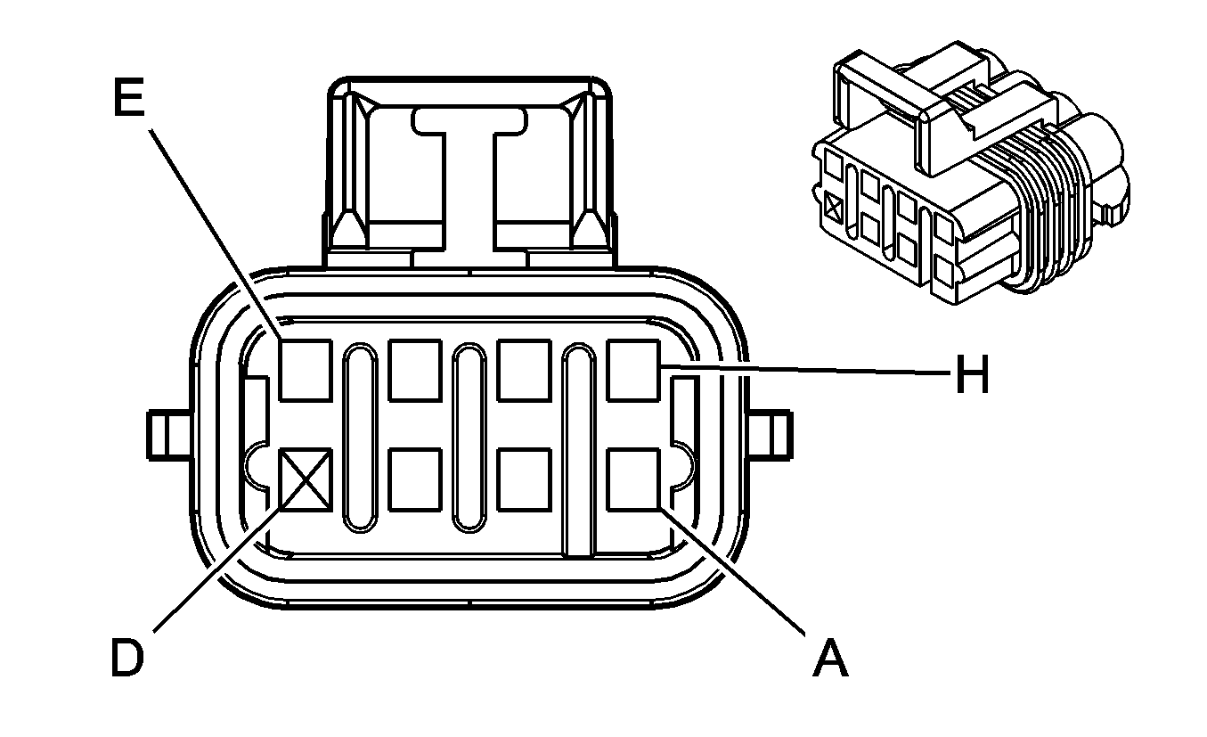
|
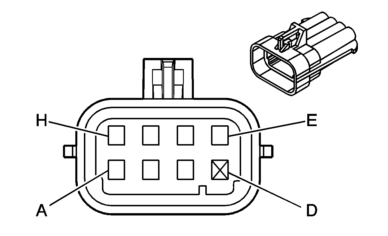
| ||||||||||||||
|---|---|---|---|---|---|---|---|---|---|---|---|---|---|---|---|
Connector Part Information |
| Connector Part Information |
| ||||||||||||
Pin | Wire Color | Circuit No. | Function | Pin | Wire Color | Circuit No. | Function | ||||||||
A | BK | 250 | Ground | A | BK | 250 | Ground | ||||||||
B | RD | 2127 | IC 7 Control | B | RD | 2127 | IC 7 Control | ||||||||
C | D-GN | 2125 | IC 5 Control | C | D-GN | 2125 | IC 5 Control | ||||||||
D | -- | -- | Not Available | D | -- | -- | Not Available | ||||||||
E | BN | 2129 | Low Reference | E | BN | 2129 | Low Reference | ||||||||
F | L-BU | 2123 | IC 3 Control | F | L-BU | 2123 | IC 3 Control | ||||||||
G | PU | 2121 | IC 1 Control | G | PU | 2121 | IC 1 Control | ||||||||
H | PK | 539 | Ignition 1 Voltage | H | PK | 539 | Ignition 1 Voltage | ||||||||

|

| ||||||||||||||
|---|---|---|---|---|---|---|---|---|---|---|---|---|---|---|---|
Connector Part Information |
| Connector Part Information |
| ||||||||||||
Pin | Wire Color | Circuit No. | Function | Pin | Wire Color | Circuit No. | Function | ||||||||
A | BK | 250 | Ground | A | BK | 250 | Ground | ||||||||
B | RD/WH | 2122 | IC 2 Control | B | RD/WH | 2122 | IC 2 Control | ||||||||
C | D-GN/WH | 2124 | IC 4 Control | C | D-GN/WH | 2124 | IC 4 Control | ||||||||
D | -- | -- | Not Available | D | -- | -- | Not Available | ||||||||
E | BN/WH | 2130 | Low Reference | E | BN/WH | 2130 | Low Reference | ||||||||
F | L-BU/WH | 2126 | IC 6 Control | F | L-BU/WH | 2126 | IC 6 Control | ||||||||
G | PU/WH | 2128 | IC 8 Control | G | PU/WH | 2128 | IC 8 Control | ||||||||
H | PK | 339 | Ignition 1 Voltage | H | PK | 339 | Ignition 1 Voltage | ||||||||
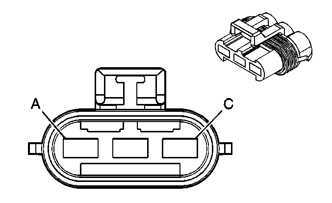
|
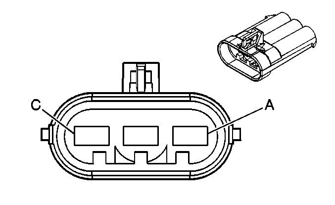
| ||||||||||||||
|---|---|---|---|---|---|---|---|---|---|---|---|---|---|---|---|
Connector Part Information |
| Connector Part Information |
| ||||||||||||
Pin | Wire Color | Circuit No. | Function | Pin | Wire Color | Circuit No. | Function | ||||||||
A | RD | IC02 | Ignition 1 Voltage | A | BK/WH | 1120 | Ignition 1 Voltage | ||||||||
B | RD/BK | IC33 | Glow Plug Supply Voltage | B | OG | 503 | Glow Plug Supply Voltage | ||||||||
C | RD | IC35 | Fuel Heater Supply Voltage | C | PK | 2677 | Fuel Heater Supply Voltage | ||||||||
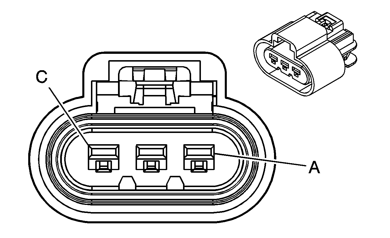
|
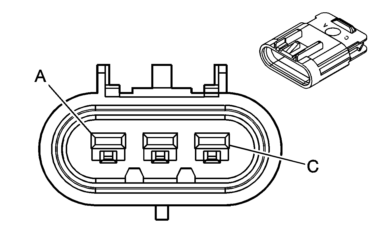
| ||||||||||||||
|---|---|---|---|---|---|---|---|---|---|---|---|---|---|---|---|
Connector Part Information |
| Connector Part Information |
| ||||||||||||
Pin | Wire Color | Circuit No. | Function | Pin | Wire Color | Circuit No. | Function | ||||||||
A | PK | 2677 | Fuel Heater Supply Voltage | A | PK | 2677 | Fuel Heater Supply Voltage | ||||||||
B | YE/BK | 508 | Water In Fuel Indicator Control | B | YE/BK | 508 | Water In Fuel Indicator Control | ||||||||
C | BK | 250 | Ground | C | BK | 250 | Ground | ||||||||

|

| ||||||||||||||
|---|---|---|---|---|---|---|---|---|---|---|---|---|---|---|---|
Connector Part Information |
| Connector Part Information |
| ||||||||||||
Pin | Wire Color | Circuit No. | Function | Pin | Wire Color | Circuit No. | Function | ||||||||
A | BK | 1744 | Fuel Injector 1 Control | A | BK | 1744 | Fuel Injector 1 Control | ||||||||
B | D-BU/WH | 878 | Fuel Injector 8 Control | B | D-BU/WH | 878 | Fuel Injector 8 Control | ||||||||
C | L-BU/BK | 844 | Fuel Injector 4 Control | C | L-BU/BK | 844 | Fuel Injector 4 Control | ||||||||
D | PK/BK | 1746 | Fuel Injector 3 Control | D | PK/BK | 1746 | Fuel Injector 3 Control | ||||||||
E | YE/BK | 846 | Fuel Injector 6 Control | E | YE/BK | 846 | Fuel Injector 6 Control | ||||||||
F | BK/WH | 845 | Fuel Injector 5 Control | F | BK/WH | 845 | Fuel Injector 5 Control | ||||||||
G | RD/BK | 877 | Fuel Injector 7 Control | G | RD/BK | 877 | Fuel Injector 7 Control | ||||||||
H | L-GN/BK | 1745 | Fuel Injector 2 Control | H | L-GN/BK | 1745 | Fuel Injector 2 Control | ||||||||
J | PK | 539 | Ignition 1 Voltage | J | PK | 539 | Ignition 1 Voltage | ||||||||
K | PK | 339 | Ignition 1 Voltage | K | PK | 339 | Ignition 1 Voltage | ||||||||
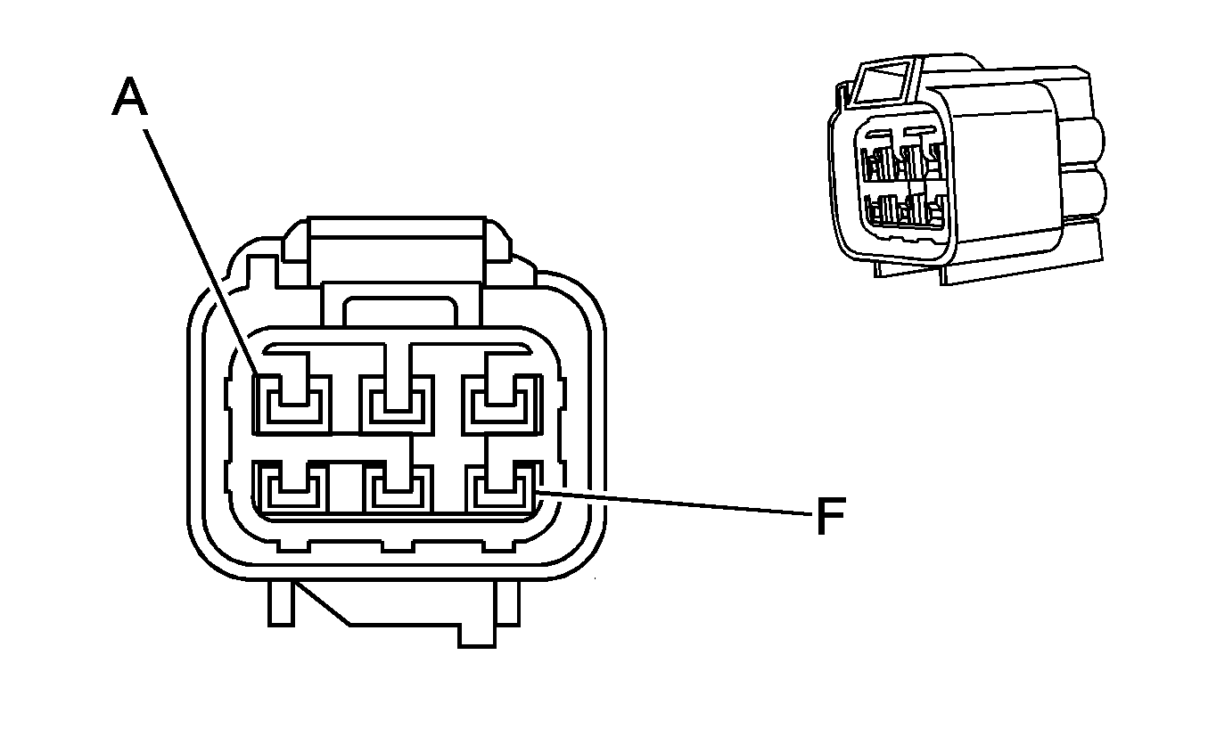
|
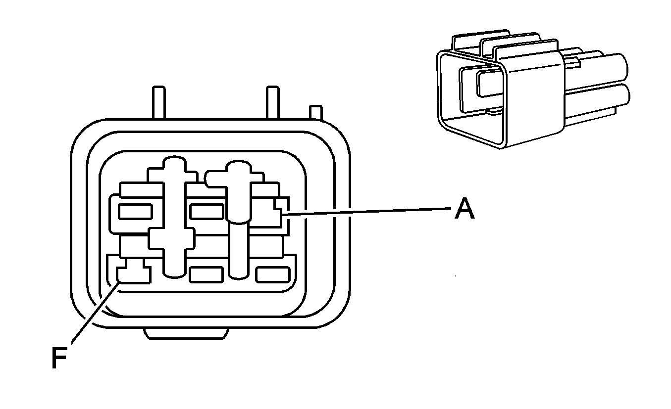
| ||||||||||||||
|---|---|---|---|---|---|---|---|---|---|---|---|---|---|---|---|
Connector Part Information |
| Connector Part Information |
| ||||||||||||
Pin | Wire Color | Circuit No. | Function | Pin | Wire Color | Circuit No. | Function | ||||||||
A | PK/YE | HB03 | Ground | A | PK/YE | HB03 | Ground | ||||||||
B | TN/WH | IC66 | Oil Pressure Sensor Signal | B | TN/WH | IC66 | Oil Pressure Sensor Signal | ||||||||
C | BN | IC68 | Oil Level Switch Signal | C | BN | IC68 | Oil Level Switch Signal | ||||||||
D | GY | IC57 | 5-Volt Reference | D | GY | IC57 | 5-Volt Reference | ||||||||
E | -- | -- | Not Used | E | -- | -- | Not Used | ||||||||
F | BK | IC71 | Low Reference | F | BK | IC71 | Low Reference | ||||||||
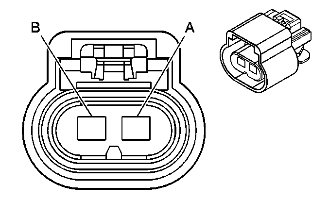
|
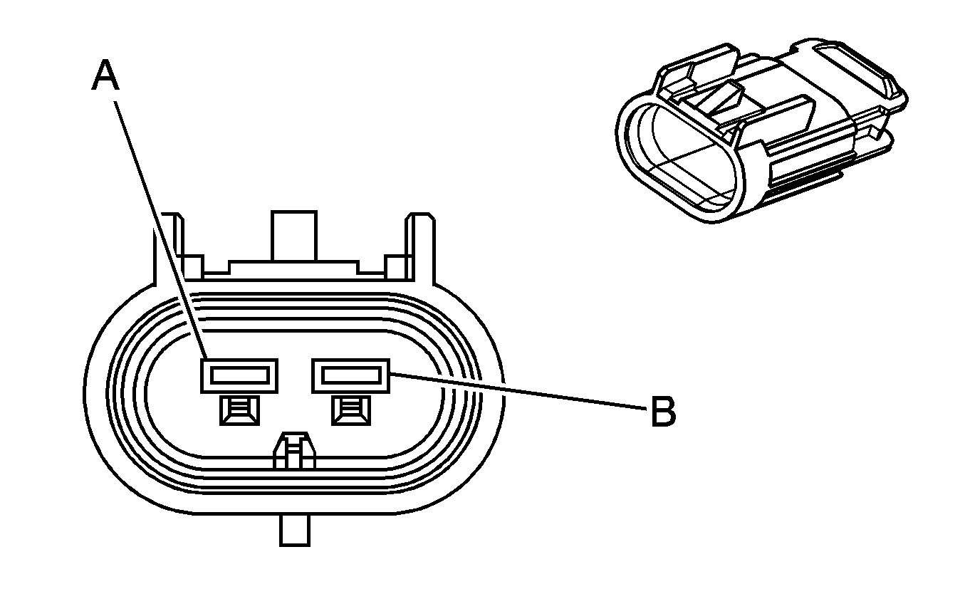
| ||||||||||||||
|---|---|---|---|---|---|---|---|---|---|---|---|---|---|---|---|
Connector Part Information |
| Connector Part Information |
| ||||||||||||
Pin | Wire Color | Circuit No. | Function | Pin | Wire Color | Circuit No. | Function | ||||||||
A | BN | 641 | Ignition 3 Voltage | A | BN | 641 | Ignition 3 Voltage | ||||||||
B | -- | -- | Not Used | B | -- | -- | Not Used | ||||||||
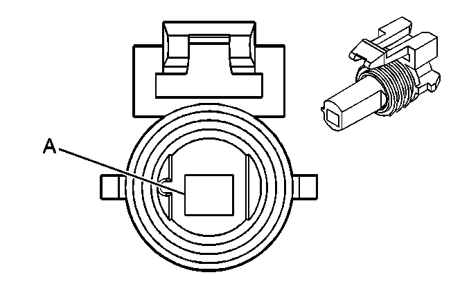
|
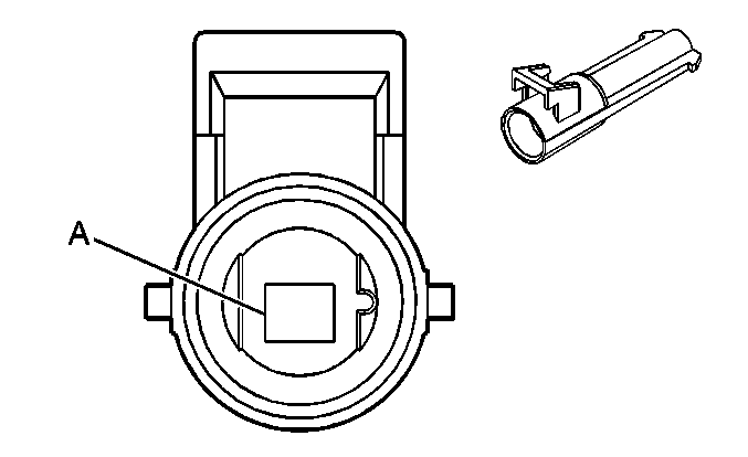
| ||||||||||||||
|---|---|---|---|---|---|---|---|---|---|---|---|---|---|---|---|
Connector Part Information |
| Connector Part Information |
| ||||||||||||
Pin | Wire Color | Circuit No. | Function | Pin | Wire Color | Circuit No. | Function | ||||||||
A | YE | 447 | Starter Relay Coil Control | A | YE | 447 | Starter Relay Coil Control | ||||||||

|

| ||||||||||||||
|---|---|---|---|---|---|---|---|---|---|---|---|---|---|---|---|
Connector Part Information |
| Connector Part Information |
| ||||||||||||
Pin | Wire Color | Circuit No. | Function | Pin | Wire Color | Circuit No. | Function | ||||||||
A | YE | 447 | Starter Relay Coil Control | A | YE | 447 | Starter Relay Coil Control | ||||||||

|

| ||||||||||||||
|---|---|---|---|---|---|---|---|---|---|---|---|---|---|---|---|
Connector Part Information |
| Connector Part Information |
| ||||||||||||
Pin | Wire Color | Circuit No. | Function | Pin | Wire Color | Circuit No. | Function | ||||||||
A | YE | 447 | Starter Relay Coil Control | A | YE | 447 | Starter Relay Coil Control | ||||||||
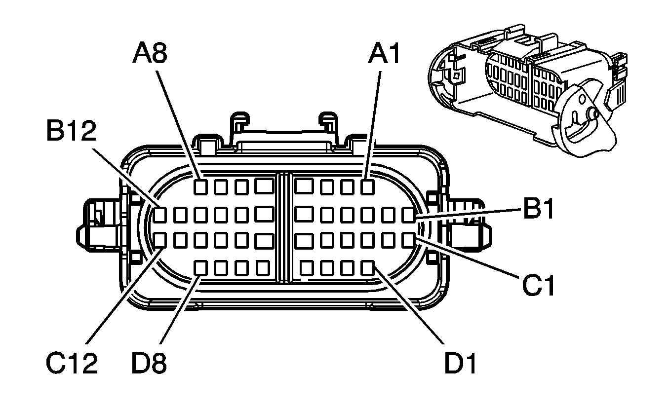
|
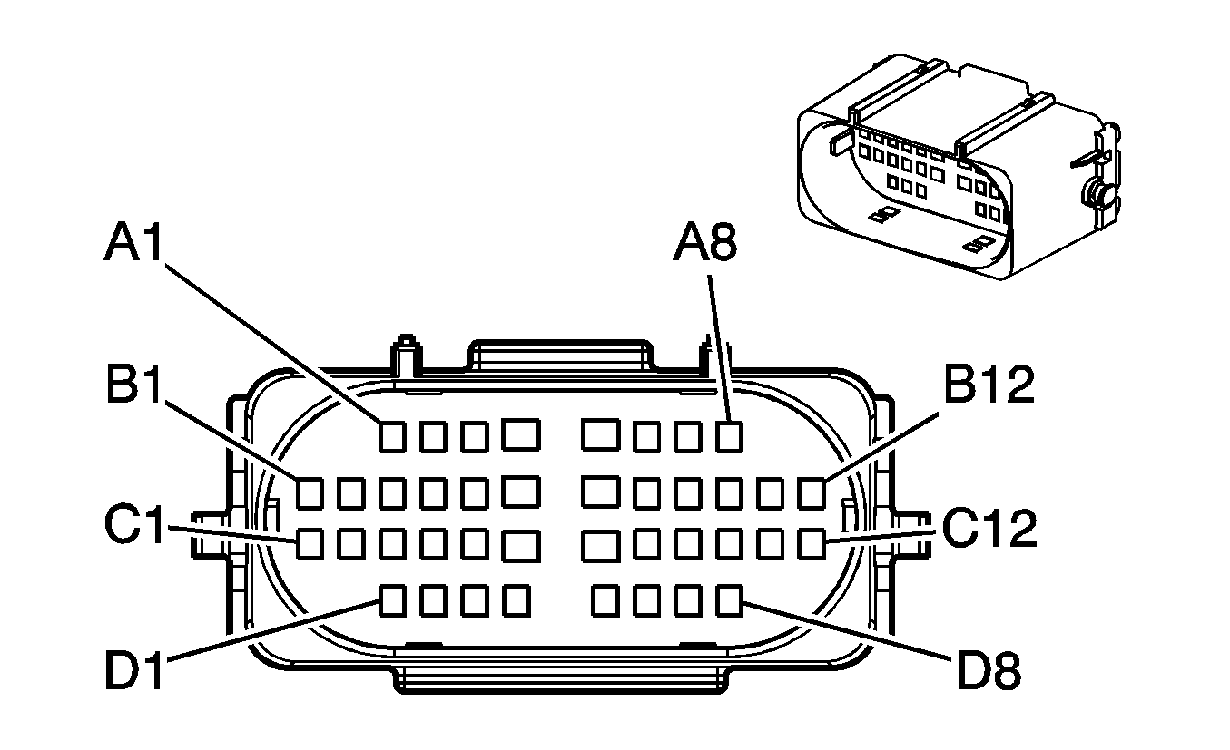
| ||||||||||||||
|---|---|---|---|---|---|---|---|---|---|---|---|---|---|---|---|
Connector Part Information |
| Connector Part Information |
| ||||||||||||
Pin | Wire Color | Circuit No. | Function | Pin | Wire Color | Circuit No. | Function | ||||||||
A1 | PK | HB02 | Ignition 1 Voltage | A1 | PK | 239 | Ignition 1 Voltage | ||||||||
A2-A3 | -- | -- | Not Used | A2-A3 | -- | -- | Not Used | ||||||||
A4 | PK | IZ20 | Ignition 1 Voltage | A4 | PK | 539 | Ignition 1 Voltage | ||||||||
A5 | PK | IZ21 | Ignition 1 Voltage | A5 | PK | 539 | Ignition 1 Voltage | ||||||||
A6 | BN | IC68 | Oil Level Switch Signal | A6 | BN | 1174 | Oil Level Switch Signal | ||||||||
A7 | YE | IC41 | ECT Sensor Signal | A7 | YE | 410 | ECT Sensor Signal | ||||||||
A8 | GY | IC47 | Low Reference | A8 | GY | 720 | Low Reference | ||||||||
B1 | L-GN/BK | IC101 | Fuel Injector 2 Control | B1 | L-GN/BK | 1745 | Fuel Injector 2 Control | ||||||||
B2 | RD/BK | IC102 | Fuel Injector 7 Control | B2 | RD/BK | 877 | Fuel Injector 7 Control | ||||||||
B3 | RD | IC26 | 12-Volt Reference | B3 | RD | 631 | 12-Volt Reference | ||||||||
B4 | BN/WH | IC27 | CMP Sensor Signal | B4 | BN/WH | 633 | CMP Sensor Signal | ||||||||
B5 | PK/BK | IC28 | Low Reference | B5 | PK/BK | 632 | Low Reference | ||||||||
B6-B7 | -- | -- | Not Used | B6-B7 | -- | -- | Not Used | ||||||||
B8 | YE/BK | IC25 | Low Reference | B8 | YE/BK | 1868 | Low Reference | ||||||||
B9 | D-BU/WH | IC24 | CKP Sensor Signal | B9 | D-BU/WH | 1869 | CKP Sensor Signal | ||||||||
B10 | L-GN | IC23 | 12-Volt Reference | B10 | L-GN | 1867 | 12-Volt Reference | ||||||||
B11 | YE/BK | IC105 | Fuel Injector 6 Control | B11 | YE/BK | 846 | Fuel Injector 6 Control | ||||||||
B12 | PK/BK | IC106 | Fuel Injector 3 Control | B12 | PK/BLK | 1746 | Fuel Injector 3 Control | ||||||||
C1 | BK | IC103 | Fuel Injector 1 Control | C1 | BK | 1744 | Fuel Injector 1 Control | ||||||||
C2 | BK/WH | IC104 | Fuel Injector 5 Control | C2 | BK/WH | 845 | Fuel Injector 5 Control | ||||||||
C3 | TN | IC37 | 5-Volt Reference | C3 | TN | 2917 | 5-Volt Reference | ||||||||
C4 | OG/BK | IC46 | Low Reference | C4 | OG/BK | 2919 | Low Reference | ||||||||
C5 | YE | IC40 | FRP Sensor Signal | C5 | YE | 2918 | FRP Sensor Signal | ||||||||
C6 | PK | IC95 | Ignition 1 Voltage | C6 | GY | 2677 | Ignition 1 Voltage | ||||||||
C7 | -- | -- | Not Used | C7 | -- | -- | Not Used | ||||||||
C8 | L-BU | IC301 | Engine Speed Signal | C8 | L-BU | 2832 | Engine Speed Signal | ||||||||
C9 | YE | IC31 | Fuel Pressure Regulator Solenoid Control | C9 | YE | 2834 | Fuel Pressure Regulator Solenoid Control | ||||||||
C10 | PU/WH | IC32 | Fuel Pressure Regulator Solenoid Supply Voltage | C10 | PU/WH | 2530 | Fuel Pressure Regulator Solenoid Supply Voltage | ||||||||
C11 | D-BU/WH | IC107 | Fuel Injector 8 Control | C11 | D-BU/WH | 878 | Fuel Injector 8 Control | ||||||||
C12 | L-BU/BK | IC108 | Fuel Injector 4 Control | C12 | L-BU/BK | 844 | Fuel Injector 4 Control | ||||||||
D1 | YE | IC43 | Fuel Temperature Signal | D1 | YE | 1578 | Fuel Temperature Signal | ||||||||
D2 | BN | IC44 | Low Reference | D2 | BN | 718 | Low Reference | ||||||||
D3 | YE/BK | IC90 | Water In Fuel Indicator Control | D3 | YE/BK | 508 | Water In Fuel Indicator Control | ||||||||
D4-D5 | -- | -- | Not Available | D4-D5 | -- | -- | Not Available | ||||||||
D6 | TN/WH | IC66 | Oil Pressure Sensor Signal | D6 | TN/WH | 332 | Oil Pressure Sensor Signal | ||||||||
D7 | BK | IC71 | Low Reference | D7 | BK | 2755 | Low Reference | ||||||||
D8 | GY | IC57 | 5-Volt Reference | D8 | GY | 2705 | 5-Volt Reference | ||||||||
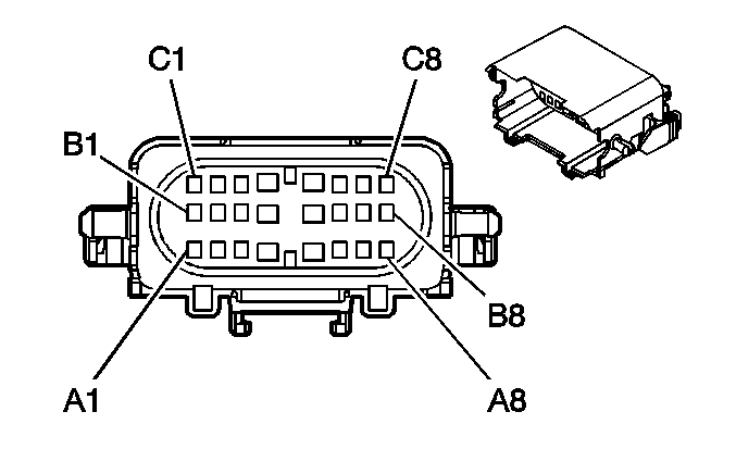
|
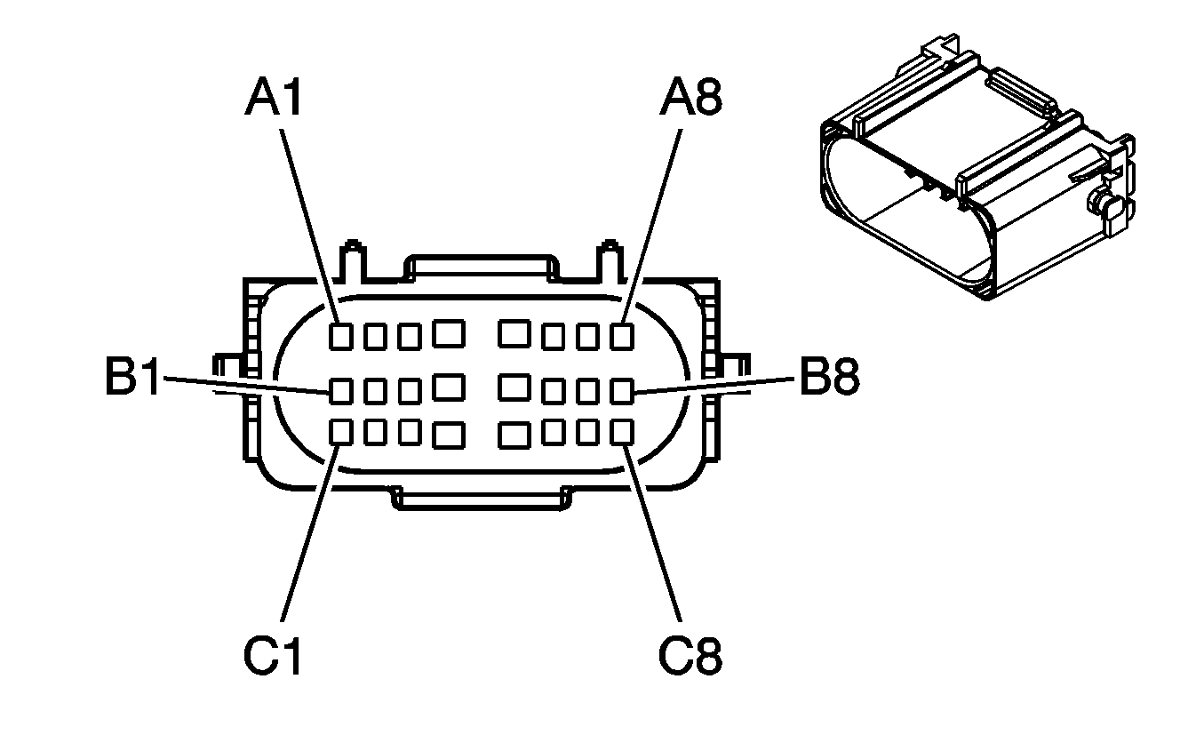
| ||||||||||||||
|---|---|---|---|---|---|---|---|---|---|---|---|---|---|---|---|
Connector Part Information |
| Connector Part Information |
| ||||||||||||
Pin | Wire Color | Circuit No. | Function | Pin | Wire Color | Circuit No. | Function | ||||||||
A1-A2 | -- | -- | Not Used | A1-A2 | -- | -- | Not Used | ||||||||
A3 | D-BU/WH | IC144 | EGR Valve Position Signal | A3 | BN/WH | 5763 | EGR Valve Position Signal | ||||||||
A4-A5 | -- | -- | Not Used | A4-A5 | -- | -- | Not Used | ||||||||
A6 | WH/BK | IC70 | 5-Volt Reference | A6 | WH/BK | 2932 | 5-Volt Reference | ||||||||
A7 | OG/BK | IC73 | Low Reference | A7 | OG/BK | 1057 | Low Reference | ||||||||
A8 | GY/BK | IC56 | BARO Sensor Signal | A8 | GY/BK | 433 | BARO Sensor Signal | ||||||||
B1 | D-GN | IC110 | SAE J1939 Serial Data Bus- | B1 | D-GN | 2362 | SAE J1939 Serial Data Bus- | ||||||||
B2 | -- | -- | Not Used | B2 | -- | -- | Not Used | ||||||||
B3 | YE/BK | IC143 | Low Reference | B3 | BK | 2754 | Low Reference | ||||||||
B4 | D-BU | IC170 | Turbocharger Vane Position Control Solenoid Valve High Control | B4 | D-BU | 5930 | Turbocharger Vane Position Control Solenoid Valve High Control | ||||||||
B5 | WH | IC171 | Low Reference | B5 | WH | 5931 | Low Reference | ||||||||
B6 | OG/BK | 5928 | 5-Volt Reference | B6 | TN | 5928 | 5-Volt Reference | ||||||||
B7 | TN | 5929 | Low Reference | B7 | OG/BK | 5929 | Low Reference | ||||||||
B8 | YE | 5947 | Turbocharger Vane Position Sensor Signal | B8 | YE | 5947 | Turbocharger Vane Position Sensor Signal | ||||||||
C1 | YE | IC109 | SAE J1939 Serial Data Bus+ | C1 | YE | 2361 | SAE J1939 Serial Data Bus+ | ||||||||
C2 | -- | -- | Not Used | C2 | -- | -- | Not Used | ||||||||
C3 | PU | IC142 | 5-Volt Reference | C3 | GY | 2703 | 5-Volt Reference | ||||||||
C4 | PK | IC140 | EGR Motor High Control | C4 | OG/BK | 5764 | EGR Motor High Control | ||||||||
C5 | WH | IC141 | EGR Motor Low Control | C5 | L-GN/BK | 5746 | EGR Motor Low Control | ||||||||
C6 | GY | IC92 | 5-Volt Reference | C6 | GY/BK | 597 | 5-Volt Reference | ||||||||
C7 | OG/BK | IC93 | Low Reference | C7 | OG/BK | 469 | Low Reference | ||||||||
C8 | L-GN | IC94 | MAP Sensor Signal | C8 | L-GN | 432 | MAP Sensor Signal | ||||||||
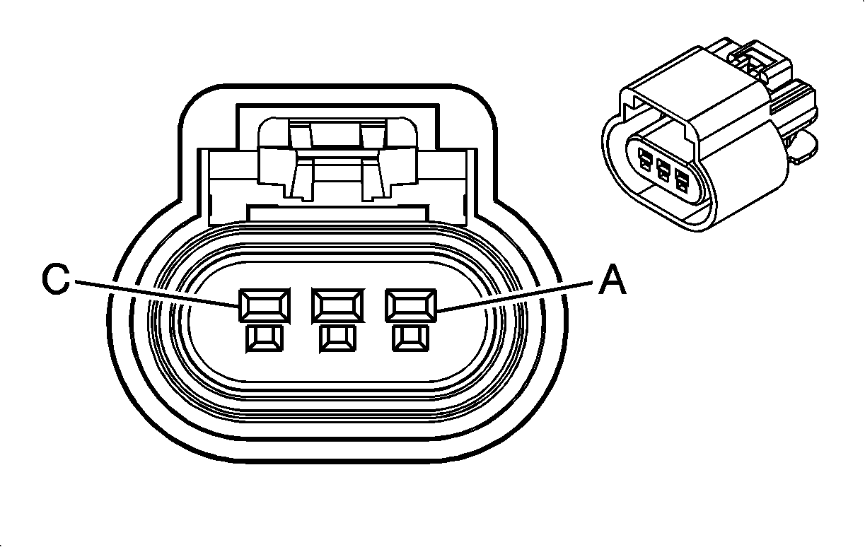
|
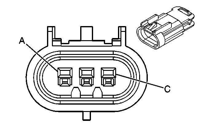
| ||||||||||||||
|---|---|---|---|---|---|---|---|---|---|---|---|---|---|---|---|
Connector Part Information |
| Connector Part Information |
| ||||||||||||
Pin | Wire Color | Circuit No. | Function | Pin | Wire Color | Circuit No. | Function | ||||||||
A | PK | 539 | Ignition 1 Voltage | A | PK | 539 | Ignition 1 Voltage | ||||||||
B | L-BU | 1998 | Intake Air Heater Indicator Control | B | L-BU | 1998 | Intake Air Heater Indicator Control | ||||||||
C | -- | -- | Not Used | C | -- | -- | Not Used | ||||||||
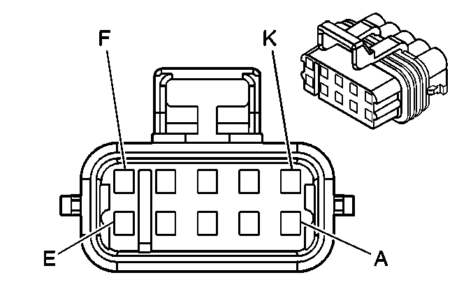
|

| ||||||||||||||||
|---|---|---|---|---|---|---|---|---|---|---|---|---|---|---|---|---|---|
Connector Part Information |
| Connector Part Information |
| ||||||||||||||
Pin | Wire Color | Circuit No. | Function | Pin | Wire Color | Circuit No. | Function | ||||||||||
A | -- | -- | Not Used | A | -- | -- | Upfitter Usage | ||||||||||
B | L-BU | 494 | Engine Shut Off-Signal | B | -- | -- | Upfitter Usage | ||||||||||
C | L-GN | 2664 | Set Coast/Tap Down | C | -- | -- | Upfitter Usage | ||||||||||
D | BK | 250 | Ground | D | -- | -- | Upfitter Usage | ||||||||||
E | PU | 2663 | Resume Accelerator/Tap Up | E | -- | -- | Upfitter Usage | ||||||||||
F | L-GN | 488 | PTO On Switch - Signal | F | -- | -- | Upfitter Usage | ||||||||||
G | YE | 2522 | PTO Engage Signal | G | -- | -- | Upfitter Usage | ||||||||||
H | WH | 2561 | PTO Supply Voltage | H | -- | -- | Upfitter Usage | ||||||||||
J | TN | 2664 | Ground | J | -- | -- | Upfitter Usage | ||||||||||
K | -- | -- | Not Used | K | -- | -- | Upfitter Usage | ||||||||||
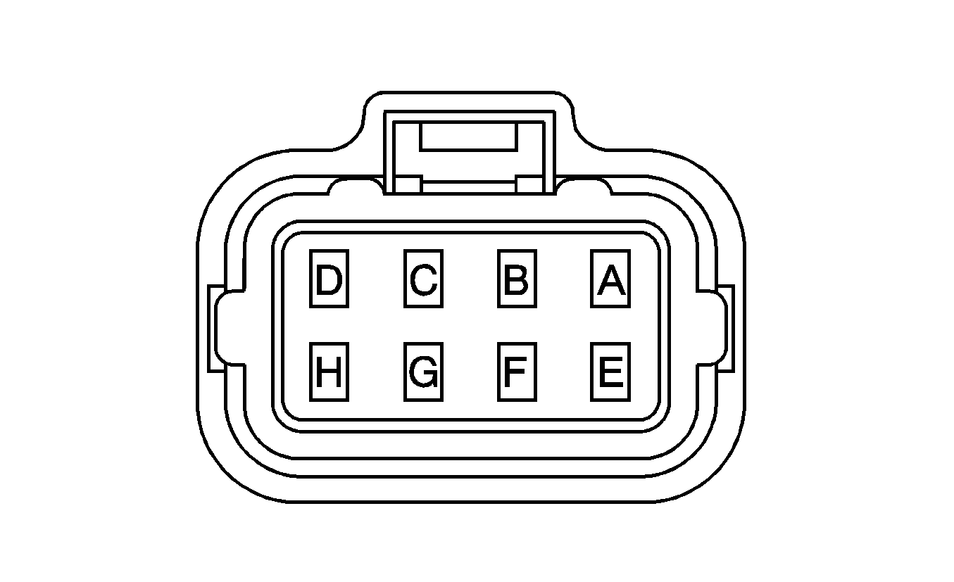
|
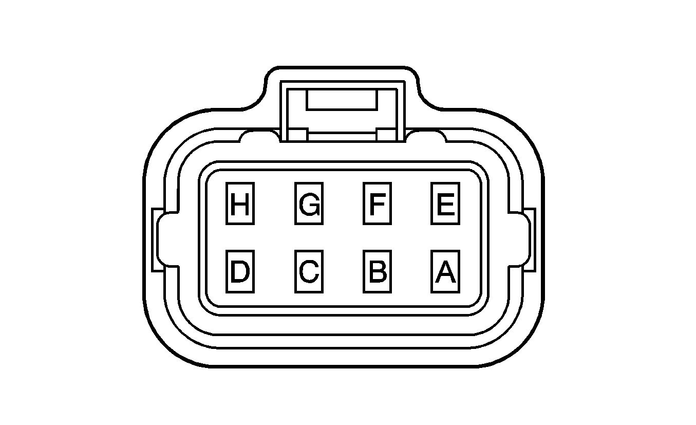
| ||||||||||||||||||||||
|---|---|---|---|---|---|---|---|---|---|---|---|---|---|---|---|---|---|---|---|---|---|---|---|
Connector Part Information |
| Connector Part Information |
| ||||||||||||||||||||
Pin | Wire Color | Circuit No. | Function | Pin | Wire Color | Circuit No. | Function | ||||||||||||||||
A | WH | B5 | Fuel Injector Supply Voltage 1 | A | WH | 7 | Fuel Injector Supply Voltage 1 | ||||||||||||||||
B | WH | B3 | Fuel Injector Supply Voltage 1 | B | WH | 4 | Fuel Injector Supply Voltage 1 | ||||||||||||||||
C | YE | B58 | Fuel Injector 1 Control | C | D-GN | 1 | Fuel Injector 1 Control | ||||||||||||||||
D-E | -- | -- | Not Used | D-E | -- | -- | Not Used | ||||||||||||||||
F | D-BU | B57 | Fuel Injector 2 Control | F | D-BU | 2 | Fuel Injector 2 Control | ||||||||||||||||
G | WH | B56 | Fuel Injector 3 Control | G | YE | 3 | Fuel Injector 3 Control | ||||||||||||||||
H | -- | -- | Not Used | H | -- | -- | Not Used | ||||||||||||||||

|

| ||||||||||||||||||||||
|---|---|---|---|---|---|---|---|---|---|---|---|---|---|---|---|---|---|---|---|---|---|---|---|
Connector Part Information |
| Connector Part Information |
| ||||||||||||||||||||
Pin | Wire Color | Circuit No. | Function | Pin | Wire Color | Circuit No. | Function | ||||||||||||||||
A | RD | B6 | Fuel Injector Supply Voltage 2 | A | RD | 7 | Fuel Injector Supply Voltage 2 | ||||||||||||||||
B | RD | B4 | Fuel Injector Supply Voltage 2 | B | RD | 4 | Fuel Injector Supply Voltage 2 | ||||||||||||||||
C | BK | B44 | Fuel Injector 4 Control | C | BK | 1 | Fuel Injector 4 Control | ||||||||||||||||
D-E | -- | -- | Not Used | D-E | -- | -- | Not Used | ||||||||||||||||
F | BK/RD | B45 | Fuel Injector 5 Control | F | BN | 2 | Fuel Injector 5 Control | ||||||||||||||||
G | RD | B43 | Fuel Injector 6 Control | G | VT | 3 | Fuel Injector 6 Control | ||||||||||||||||
H | -- | -- | Not Used | H | -- | -- | Not Used | ||||||||||||||||
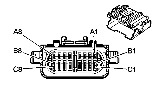
|

| ||||||||||||||
|---|---|---|---|---|---|---|---|---|---|---|---|---|---|---|---|
Connector Part Information |
| Connector Part Information |
| ||||||||||||
Pin | Wire Color | Circuit No. | Function | Pin | Wire Color | Circuit No. | Function | ||||||||
A1 | GY | 1273 | Low Reference (L18/LLY) | A1 | GY | 1273 | Low Reference (L18/LLY) | ||||||||
BK | 28 | Horn Relay Control (LG4) | BK | 28 | Horn Relay Control (LG4) | ||||||||||
A2 | PU | 1272 | Low Reference (L18/LLY) | A2 | PU | 1272 | Low Reference (L18/LLY) | ||||||||
PK | 139 | Ignition 1 Voltage (LG4) | PK | 139 | Ignition 1 Voltage (LG4) | ||||||||||
A3 | L-BU | 1162 | APP Sensor 2 Signal (L18/LLY) | A3 | L-BU | 1162 | APP Sensor 2 Signal (L18/LLY) | ||||||||
A4 | OG | 1440 | Battery Positive voltage (L18/LLY) | A4 | OG | 1440 | Battery Positive Voltage (L18/LLY) | ||||||||
RD | 1440 | Battery Positive Voltage (LG4) | RD | 1440 | Battery Positive Voltage (LG4) | ||||||||||
A5 | PK | 2677 | Fuel Heater Control (LG4/LG5/LLY) | A5 | PK | 2677 | Fuel Heater Control (LG4/LG5/LLY) | ||||||||
A6 | TN | 1274 | 5-Volt Reference (L18/LLY) | A6 | TN | 1274 | 5-Volt Reference (L18/LLY) | ||||||||
PK | 439 | Ignition 1 Voltage (LG4) | PK | 439 | Ignition 1 Voltage (LG4) | ||||||||||
A7 | YE/BK | 1275 | 5-Volt Reference (L18/LLY) | A7 | YE/BK | 1275 | 5-Volt Reference (L18/LLY) | ||||||||
D-BU | 84 | Cruise Control Set/Coast Switch Signal (LG4) | D-BU | 84 | Cruise Control Set/Coast Switch Signal (LG4) | ||||||||||
A8 | D-BU | 1161 | APP Sensor 1 Signal (L18/LLY) | A8 | D-BU | 1161 | APP Sensor 1 Signal (L18/LLY) | ||||||||
YE | 2470 | Class 2 Serial Data (LG4) | YE | 2470 | Class 2 Serial Data (LG4) | ||||||||||
B1 | WH/BK | 1164 | 5-Volt Reference (L18/LLY) | B1 | WH/BK | 1164 | 5-Volt Reference (L18/LLY) | ||||||||
GY/BK | 87 | Cruise Control Resume/Accel Switch Signal (LG4) | GY/BK | 87 | Cruise Control Resume/Accel Switch Signal (LG4) | ||||||||||
B2 | BN | 1271 | Low Reference (L18/LLY) | B2 | BN | 1271 | Low Reference (L18/LLY) | ||||||||
OG | 440 | Battery Positive Voltage (LG4) | OG | 440 | Battery Positive Voltage (LG4) | ||||||||||
B3 | D-GN | 1163 | APP Sensor 3 Signal (L18/LLY) | B3 | D-GN | 1163 | APP Sensor 3 Signal (L18/LLY) | ||||||||
L-GN | 66 | A/C Request Signal (LG4) | L-GN | 66 | A/C Request Signal (LG4) | ||||||||||
B4 | D-GN | 1433 | PNP/Clutch Start Switch Signal (Manual Transmission) | B4 | D-GN | 1433 | PNP/Clutch Start Switch Signal (Manual Transmission) | ||||||||
B5 | GY/BK | 1694 | 4WD Low Signal | B5 | GY/BK | 1694 | 4WD Low Signal | ||||||||
B6 | WH | 121 | Engine Speed Signal (L18/LLY) | B6 | WH | 121 | Engine Speed Signal (L18/LLY) | ||||||||
PK | 239 | Ignition 1 Voltage (LG4) | PK | 239 | Ignition 1 Voltage (LG4) | ||||||||||
B7 | GY | 1234 | Do Not Shift Indicator Control | B7 | GY | 1234 | Do Not Shift Indicator Control | ||||||||
B8 | YE/BK | 508 | Water In Fuel Indicator Control (School Bus w/LLY or w/L18) | B8 | YE/BK | 508 | Water In Fuel Indicator Control (School Bus w/LLY or w/L18) | ||||||||
PU | 806 | Crank Voltage (LG4) | PU | 806 | Crank Voltage (LG4) | ||||||||||
C1 | L-GN | 488 | PTO On Switch Signal | C1 | L-GN | 488 | PTO On Switch Signal | ||||||||
C2 | D-GN | 1020 | Ignition 0 Voltage | C2 | PU | 1020 | Ignition 0 Voltage | ||||||||
C3 | RD | 2013 | High Idle Indicator Control (L18/LLY) | C3 | OG | 2013 | High Idle Indicator Control (L18/LLY) | ||||||||
PU | 806 | Crank Voltage (LG4) | PU | 806 | Crank Voltage (LG4) | ||||||||||
C4 | PU | 1093 | Rear Defog Element Supply Voltage (L18/LLY) | C4 | PU | 1093 | Rear Defog Element Supply Voltage (L18/LLY) | ||||||||
PK | 339 | Ignition 1 Voltage (LG4) | PK | 339 | Ignition 1 Voltage (LG4) | ||||||||||
C5 | TN/WH | 2678 | Overdrive Defeat Switch Signal (L18/LLY) | C5 | TN/WH | 2678 | Overdrive Defeat Switch Signal (L18/LLY) | ||||||||
OG | 1440 | Battery Positive Voltage (LG4) | OG | 1440 | Battery Positive Voltage (LG4) | ||||||||||
C6 | YE | 2361 | SAE J1939 Serial Data Bus+ | C6 | YE | 2361 | SAE J1939 Serial Data Bus+ | ||||||||
C7 | D-GN | 2362 | SAE J1939 Serial Data Bus- | C7 | D-GN | 2362 | SAE J1939 Serial Data Bus- | ||||||||
C8 | PU | 806 | Crank Voltage | C8 | PU | 806 | Crank Voltage | ||||||||
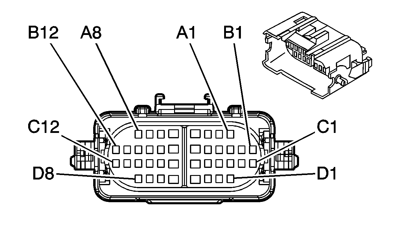
|

| ||||||||||||||
|---|---|---|---|---|---|---|---|---|---|---|---|---|---|---|---|
Connector Part Information |
| Connector Part Information |
| ||||||||||||
Pin | Wire Color | Circuit No. | Function | Pin | Wire Color | Circuit No. | Function | ||||||||
A1 | -- | -- | Not Used | A1 | -- | -- | Not Used | ||||||||
A2 | D-GN | 21 | Marker Lamps Supply Voltage | A2 | D-GN | 21 | Marker Lamps Supply Voltage | ||||||||
A3 | -- | -- | Not Used | A3 | -- | -- | Not Used | ||||||||
A4 | D-BU | 47 | Trailer Auxiliary Supply Voltage | A4 | D-BU | 47 | Trailer Auxiliary Supply Voltage | ||||||||
A5 | RD | 642 | Battery Positive Voltage | A5 | RD | 642 | Battery Positive Voltage | ||||||||
A6 | PK | 439 | Ignition 1 Voltage | A6 | PK | 439 | Ignition 1 Voltage | ||||||||
A7 | GY | 2260 | Driver Satellite Return | A7 | GY | 2260 | Driver Satellite Return | ||||||||
A8 | L-BU | 1122 | ABS/TCS Class 2 Serial Data | A8 | L-BU | 1122 | ABS/TCS Class 2 Serial Data | ||||||||
B1 | D-BU | 2769 | Brake Indicator Signal | B1 | D-BU | 2769 | Brake Indicator Signal | ||||||||
B2 | BN | 641 | Ignition 3 Voltage | B2 | BN | 641 | Ignition 3 Voltage | ||||||||
B3 | YE | 1834 | Forward Discriminating Sensor Signal | B3 | YE | 1834 | Forward Discriminating Sensor Signal | ||||||||
B4 | BN/WH | 2609 | Right Rear Park Lamps Supply Voltage | B4 | BN/WH | 2609 | Right Rear Park Lamps Supply Voltage | ||||||||
B5 | BN | 141 | Ignition 3 Voltage | B5 | BN | 141 | Ignition 3 Voltage | ||||||||
B6 | TN | 12 | Headlamp Low Beam Supply Voltage | B6 | TN | 12 | Headlamp Low Beam Supply Voltage | ||||||||
B7 | L-GN | 11 | Headlamp High Beam Supply Voltage | B7 | L-GN | 11 | Headlamp High Beam Supply Voltage | ||||||||
B8-B12 | -- | -- | Not Used | B8-B12 | -- | -- | Not Used | ||||||||
C1 | BN/WH | 1571 | Traction Control Switch Signal | C1 | BN/WH | 1571 | Traction Control Switch Signal | ||||||||
C2 | L-BU | 832 | Traction Control Active Signal | C2 | L-BU | 832 | Traction Control Active Signal | ||||||||
C3 | WH | 1808 | Service Traction Control Signal | C3 | WH | 1808 | Service Traction Control Signal | ||||||||
C4 | -- | -- | Not Used | C4 | -- | -- | Not Used | ||||||||
C5 | L-GN/BK | 431 | 5-Volt Reference | C5 | L-GN/BK | 431 | 5-Volt Reference | ||||||||
C6 | BN | 9 | Park Lamp Supply Voltage | C6 | BN | 9 | Park Lamp Supply Voltage | ||||||||
C7 | WH | 17 | Stop Lamp Supply Voltage | C7 | WH | 17 | Stop Lamp Supply Voltage | ||||||||
C8 | BN | 541 | Ignition 3 Voltage | C8 | BN | 541 | Ignition 3 Voltage | ||||||||
C9 | PU | 806 | Crank Voltage | C9 | PU | 806 | Crank Voltage | ||||||||
C10 | YE | 318 | Left Rear Trailer Stop/Turn Lamp Supply Voltage | C10 | YE | 318 | Left Rear Trailer Stop/Turn Lamp Supply Voltage | ||||||||
C11 | TN/WH | 585 | Transmission Fluid Temperature Sensor Signal | C11 | TN/WH | 585 | Transmission Fluid Temperature Sensor Signal | ||||||||
C12 | BN | 2509 | Left Rear Park Lamps Supply Voltage | C12 | BN | 2509 | Left Rear Park Lamps Supply Voltage | ||||||||
D1 | D-GN | 319 | Right Rear Trailer Stop/Turn Lamp Supply Voltage | D1 | D-GN | 319 | Right Rear Trailer Stop/Turn Lamp Supply Voltage | ||||||||
D2 | BN/WH | 1555 | Encoder Signal | D2 | BN/WH | 1555 | Encoder Signal | ||||||||
D3 | L-BU | 1320 | Stop Lamp Supply Voltage | D3 | L-BU | 1320 | Stop Lamp Supply Voltage | ||||||||
D4 | YE | 618 | Left Rear Turn Signal Lamp Supply Voltage | D4 | YE | 618 | Left Rear Turn Signal Lamp Supply Voltage | ||||||||
D5 | D-GN | 619 | Right Rear Turn Signal Lamp Supply Voltage | D5 | D-GN | 619 | Right Rear Turn Signal Lamp Supply Voltage | ||||||||
D6 | BK/WH | 1554 | Encoder Low Reference | D6 | BK/WH | 1554 | Encoder Low Reference | ||||||||
D7 | L-BU | 14 | Left Turn Signal Lamps Supply Voltage | D7 | L-BU | 14 | Left Turn Signal Lamps Supply Voltage | ||||||||
D8 | D-BU | 15 | Right Turn Signal Lamps Supply Voltage | D8 | D-BU | 15 | Right Turn Signal Lamps Supply Voltage | ||||||||
|
| ||||||||||||||
|---|---|---|---|---|---|---|---|---|---|---|---|---|---|---|---|
Connector Part Information |
| Connector Part Information |
| ||||||||||||
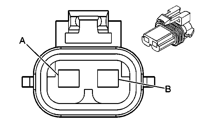
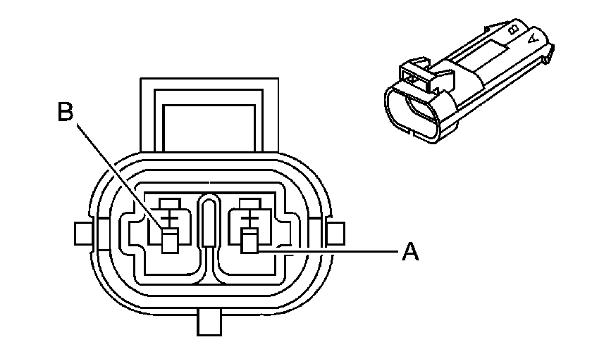
Pin | Wire Color | Circuit No. | Function | Pin | Wire Color | Circuit No. | Function | ||||||||
A | BK | 1552 | Motor Control A | A | BK | 1552 | Motor Control A | ||||||||
B | RD | 1553 | Motor Control B | B | RD | 1553 | Motor Control B | ||||||||
|
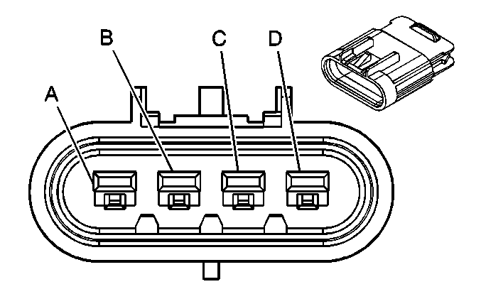
| ||||||||||
|---|---|---|---|---|---|---|---|---|---|---|---|
Connector Part Information |
| Connector Part Information | 4-Way M GT 280 Series, Sealed (BK) | ||||||||
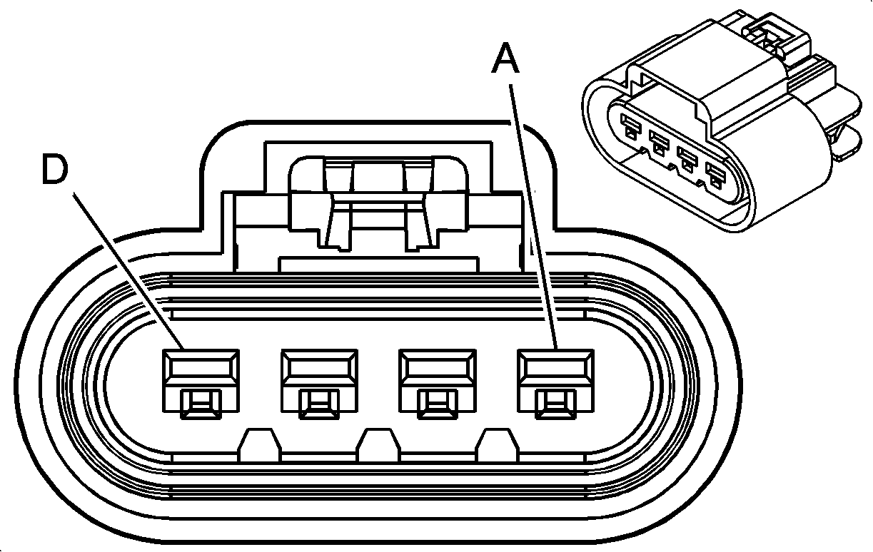
Pin | Wire Color | Circuit No. | Function | Pin | Wire Color | Circuit No. | Function | ||||
A | RD | 228 | Windshield Washer Pump Control | A | RD | 228 | Windshield Washer Pump Control | ||||
B | BK | 750 | Ground | B | BK | 750 | Ground | ||||
C | TN | 185 | Low Washer Fluid Indicator Signal | C | TN | 185 | Low Washer Fluid Indicator Signal | ||||
D | BK | 750 | Ground | D | BK | 750 | Ground | ||||
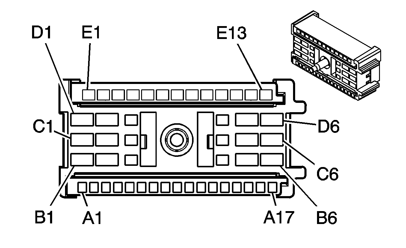
|
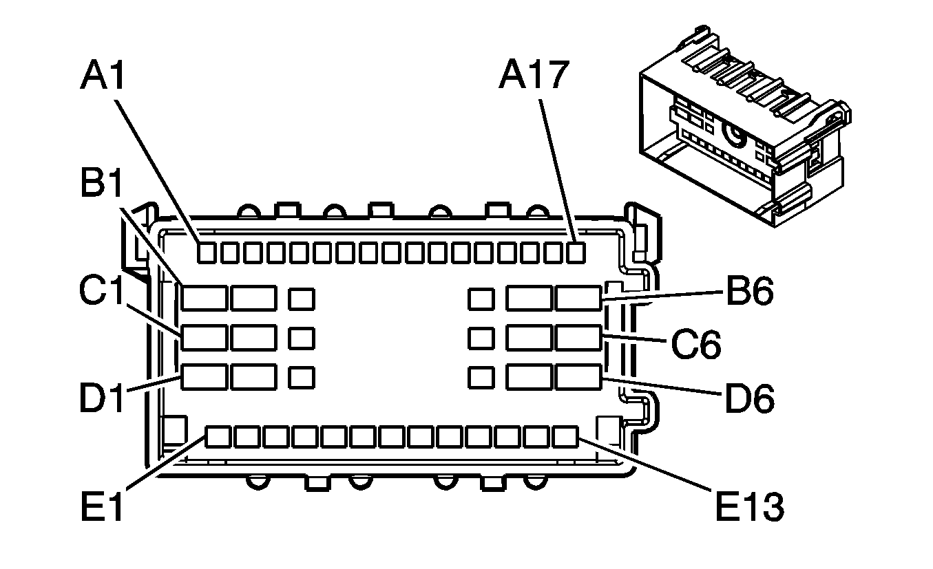
| ||||||||||||||||||||||
|---|---|---|---|---|---|---|---|---|---|---|---|---|---|---|---|---|---|---|---|---|---|---|---|
Connector Part Information |
| Connector Part Information |
| ||||||||||||||||||||
Pin | Wire Color | Circuit No. | Function | Pin | Wire Color | Circuit No. | Function | ||||||||||||||||
A1 | WH | -- | Not Used | A1 | -- | -- | Not Used | ||||||||||||||||
A2 | PK | 139 | Ignition 1 Voltage | A2 | PK | 139 | Ignition 1 Voltage | ||||||||||||||||
A3 | L-BU | 1696 | Turn/Hazard Module 2 Supply Voltage | A3 | GY | 1696 | Turn/Hazard Module 2 Supply Voltage | ||||||||||||||||
A4-A5 | -- | -- | Not Used | A4-A5 | -- | -- | Not Used | ||||||||||||||||
A6 | D-BU | 15 | Right Turn Signal Lamps Supply Voltage | A6 | D-BU | 15 | Right Turn Signal Lamps Supply Voltage | ||||||||||||||||
A7 | L-BU | 14 | Left Turn Signal Lamps Supply Voltage | A7 | L-BU | 14 | Left Turn Signal Lamps Supply Voltage | ||||||||||||||||
A8-A10 | -- | -- | Not Used | A8-A10 | -- | -- | Not Used | ||||||||||||||||
A11 | BK | 28 | Horn Relay Control | A11 | BK | 28 | Horn Relay Control | ||||||||||||||||
A12 | GY | 397 | Cruise Control On Switch Signal | A12 | GY | 397 | Cruise Control On Switch Signal | ||||||||||||||||
A13 | BK | 639 | Ignition 1 Voltage | A13 | PK | 639 | Ignition 1 Voltage | ||||||||||||||||
A14 | D-BU | 84 | Cruise Control Set/Coast Switch Signal | A14 | D-BU | 84 | Cruise Control Set/Coast Switch Signal | ||||||||||||||||
A15 | GY | 87 | Cruise Control Resume/Accel Switch Signal | A15 | GY/BK | 87 | Cruise Control Resume/Accel Switch Signal | ||||||||||||||||
A16 | BK | -- | Not Used | A16 | -- | -- | Not Used | ||||||||||||||||
A17 | D-GN/WH | -- | Not Used | A17 | -- | -- | Not Used | ||||||||||||||||
B1 | -- | -- | Not Used | B1 | -- | -- | Not Used | ||||||||||||||||
B2 | BK | -- | Not Used | B2 | -- | -- | Not Used | ||||||||||||||||
B3 | L-GN | 80 | Key In Ignition Switch Signal | B3 | L-GN | 80 | Key In Ignition Switch Signal | ||||||||||||||||
B4 | TN | 159 | Key Out Ignition Switch Signal | B4 | TN | 159 | Key Out Ignition Switch Signal | ||||||||||||||||
B5 | TN/WH | -- | Not Used | B5 | -- | -- | Not Used | ||||||||||||||||
B6 | -- | -- | Not Used | B6 | -- | -- | Not Used | ||||||||||||||||
C1 | WH | 1390 | Off/Run/Crank Voltage | C1 | WH | 1390 | Off/Run/Crank Voltage | ||||||||||||||||
C2 | BK/WH | 750 | Ground | C2 | BK/WH | 750 | Ground | ||||||||||||||||
C3-C4 | -- | -- | Not Used | C3-C4 | -- | -- | Not Used | ||||||||||||||||
C5 | PK | 3 | Ignition 1 Voltage | C5 | PK | 3 | Ignition 1 Voltage | ||||||||||||||||
C6 | OG | 300 | Ignition 3 Voltage | C6 | OG | 300 | Ignition 3 Voltage | ||||||||||||||||
D1 | YE | 5 | Crank Voltage | D1 | YE | 5 | Crank Voltage | ||||||||||||||||
D2 | RD | 342 | Battery Positive Voltage | D2 | RD | 342 | Battery Positive Voltage | ||||||||||||||||
D3-D4 | -- | -- | Not Used | D3-D4 | -- | -- | Not Used | ||||||||||||||||
D5 | RD/WH | 242 | Battery Positive Voltage | D5 | RD/WH | 242 | Battery Positive Voltage | ||||||||||||||||
D6 | BN | 4 | Accessory Voltage | D6 | BN | 4 | Accessory Voltage | ||||||||||||||||
E1 | L-GN | 1696 | Turn/Hazard Module 2 Supply Voltage | E1 | GY | 1696 | Turn/Hazard Module 2 Supply Voltage | ||||||||||||||||
E2 | WH | 895 | Left Rear Stop Lamp Supply Voltage | E2 | YE | 895 | Left Rear Stop Lamp Supply Voltage | ||||||||||||||||
E3 | PU | 92 | Windshield Wiper Motor High Speed | E3 | PU | 92 | Windshield Wiper Motor High Speed | ||||||||||||||||
E4 | YE | 43 | Accessory Voltage | E4 | YE | 43 | Accessory Voltage | ||||||||||||||||
E5 | GY | 96 | Windshield Wiper Switch Pulse Delay Signal | E5 | BN | 96 | Windshield Wiper Switch Pulse Delay Signal | ||||||||||||||||
E6 | D-GN | 19 | Right Turn Lamp Supply Voltage | E6 | D-GN | 19 | Right Turn Lamp Supply Voltage | ||||||||||||||||
E7 | YE | 18 | Left Turn Lamp Supply Voltage | E7 | YE | 18 | Left Turn Lamp Supply Voltage | ||||||||||||||||
E8 | OG | 1040 | Battery Positive Voltage | E8 | OG | 1040 | Battery Positive Voltage | ||||||||||||||||
E9 | PU | 1697 | Turn/Hazard Module Signal | E9 | PU | 1697 | Turn/Hazard Module Signal | ||||||||||||||||
E10 | -- | -- | Not Used | E10 | -- | -- | Not Used | ||||||||||||||||
E11 | L-GN | 11 | Headlamp High Beam Supply Voltage | E11 | L-GN | 11 | Headlamp High Beam Supply Voltage | ||||||||||||||||
E12 | TN | 544 | Headlamp Low Beam Supply Voltage | E12 | PU | 544 | Headlamp Low Beam Supply Voltage | ||||||||||||||||
E13 | L-BU | 10 | Headlamp Switch Signal | E13 | YE | 10 | Headlamp Switch Signal | ||||||||||||||||
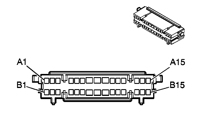
|
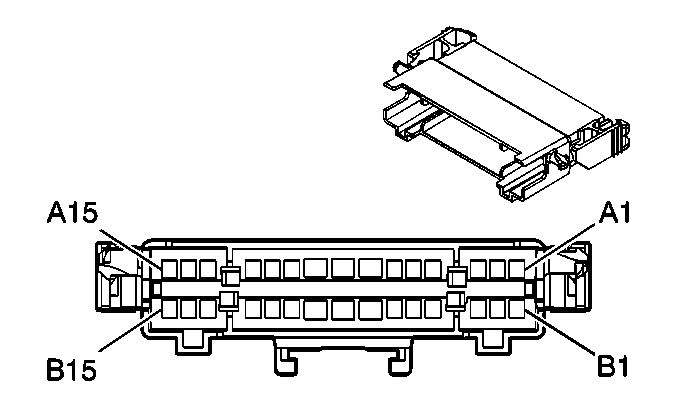
| ||||||||||||||
|---|---|---|---|---|---|---|---|---|---|---|---|---|---|---|---|
Connector Part Information |
| Connector Part Information |
| ||||||||||||
Pin | Wire Color | Circuit No. | Function | Pin | Wire Color | Circuit No. | Function | ||||||||
A1 | L-GN | 488 | PTO On Switch Signal | A1 | L-GN | 488 | PTO On Switch Signal | ||||||||
A2 | RD | 2013 | High Idle Indicator Control (w/o L18) | A2 | RD | 2013 | High Idle Indicator Control (w/o L18) | ||||||||
A3 | D-GN | 534 | High Idle Switch Signal (w/o L18) | A3 | D-GN | 534 | High Idle Switch Signal (w/o L18) | ||||||||
A4 | WH | 1808 | Service Traction Control Signal | A4 | WH | 1808 | Service Traction Control Signal | ||||||||
A5 | L-BU | 832 | Traction Control Active Signal | A5 | L-BU | 832 | Traction Control Active Signal | ||||||||
A6 | BN/WH | 1571 | Traction Control Switch Signal | A6 | BN/WH | 1571 | Traction Control Switch Signal | ||||||||
A7 | D-BU | 1944 | Suspension Dump Valve Solenoid Control | A7 | D-BU | 1944 | Suspension Dump Valve Solenoid Control (C6/C7/C8) | ||||||||
-- | -- | Not Used (C4/C5) | |||||||||||||
A8 | PK | 239 | Ignition 1 Voltage | A8 | PK | 239 | Ignition 1 Voltage | ||||||||
A9 | -- | -- | Not Used | A9 | -- | -- | Not Used | ||||||||
A10 | -- | -- | Not Used | A10 | TN/BK | -- | Not Used | ||||||||
A11 | -- | -- | Not Used | A11 | PK | -- | Not Used | ||||||||
A12 | BN | 541 | Ignition 3 Voltage | A12 | BN | 541 | Ignition 3 Voltage (L18/LG4/LG5) | ||||||||
-- | -- | Not Used (LLY) | |||||||||||||
A13 | OG/BK | 2666 | Battery Positive Voltage | A13 | OG/BK | 2666 | Battery Positive Voltage | ||||||||
A14 | D-GN | 239 | Ignition 1 Voltage | A14 | L-GN | 239 | Ignition 1 Voltage (L18) | ||||||||
L-GN | 488 | PTO On Switch Signal (LG4/LLY) | |||||||||||||
A15 | BN | 2509 | Left Rear Park Lamps Supply Voltage | A15 | BN | 2509 | Left Rear Park Lamps Supply Voltage | ||||||||
B1 | OG | 267 | Heated Mirror Supply Voltage | B1 | OG | 267 | Heated Mirror Supply Voltage | ||||||||
B2 | BN | 441 | Ignition 3 Voltage | B2 | BN | 441 | Ignition 3 Voltage (L18/LG4/LLY) | ||||||||
OG | 2013 | High Idle Indicator Control (LG5) | |||||||||||||
B3 | L-GN | 2081 | Exhaust Brake Request Signal | B3 | L-GN | 2081 | Exhaust Brake Request Signal (LG4/LG5/LLY) | ||||||||
-- | -- | Not Used (L18) | |||||||||||||
B4 | BK | 451 | Ground | B4 | BK | 451 | Ground | ||||||||
B5 | BN | 541 | Ignition 3 Voltage | B5 | BN | 541 | Ignition 3 Voltage | ||||||||
B6 | -- | -- | Not Used | B6 | YE | 1139 | Ignition 1 Voltage | ||||||||
B7 | BK | 750 | Ground | B7 | BK | 750 | Ground | ||||||||
B8 | -- | -- | Not Used | B8 | PU/WH | 1382 | LED Dimming Signal | ||||||||
B9 | -- | -- | Not Used | B9 | -- | -- | Not Used | ||||||||
B10 | BN | 641 | Ignition 3 Voltage | B10 | BN | 641 | Ignition 3 Voltage | ||||||||
B11 | -- | -- | Not Used | B11 | GY | 8 | Instrument Panel Lamp Supply Voltage - 1 | ||||||||
B12 | BK | 750 | Ground | B12 | BK | 750 | Ground (LG4/LLY) | ||||||||
YE | 32 | Instrument Panel Lamp Fuse Supply Voltage (L18) | |||||||||||||
B13 | -- | -- | Not Used | B13 | -- | -- | Not Used | ||||||||
B14 | GY/BK | 1467 | Shift Motor Relay - Control | B14 | -- | -- | Not Used | ||||||||
B15 | PK | 239 | Ignition 1 Voltage | B15 | -- | -- | Not Used | ||||||||
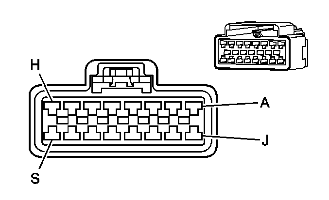
|
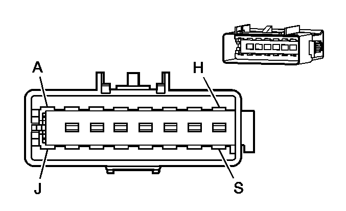
| ||||||||||||||
|---|---|---|---|---|---|---|---|---|---|---|---|---|---|---|---|
Connector Part Information |
| Connector Part Information |
| ||||||||||||
Pin | Wire Color | Circuit No. | Function | Pin | Wire Color | Circuit No. | Function | ||||||||
A | D-GN | 21 | Marker Lamps Supply Voltage (w/o UZA) | A | D-GN | 21 | Marker Lamps Supply Voltage (w/o UZA) | ||||||||
-- | -- | Not used (UZA) | -- | -- | Not used (UZA) | ||||||||||
B | BK | 750 | Ground | B | BK | 750 | Ground | ||||||||
C | OG | 40 | Battery Positive Voltage | C | OG | 40 | Battery Positive Voltage | ||||||||
D | WH | 156 | Courtesy Lamp Switch Signal | D | WH | 156 | Courtesy Lamp Switch Signal | ||||||||
E | YE | 1139 | Ignition 1 Voltage (AJ3/AK5) | E | YE | 1139 | Ignition 1 Voltage (AJ3/AK5) | ||||||||
-- | -- | Not Used (AL3) | -- | -- | Not Used (AL3) | ||||||||||
F | D-GN | 348 | Steering Wheel Module - Low Control (AJ3/AK5) | F | D-GN | 348 | Steering Wheel Module - Low Control (AJ3/AK5) | ||||||||
-- | -- | Not Used (AL3) | -- | -- | Not Used (AL3) | ||||||||||
G | WH | 347 | Steering Wheel Module - High Control (AJ3/AK5) | G | WH | 347 | Steering Wheel Module - High Control (AJ3/AK5) | ||||||||
-- | -- | Not Used (AL3) | -- | -- | Not Used (AL3) | ||||||||||
H | D-BU | 1128 | SDM Class 2 Serial Data (AJ3/AK5) | H | D-BU | 1128 | SDM Class 2 Serial Data (AJ3/AK5) | ||||||||
-- | -- | Not Used (AL3) | -- | -- | Not Used (AL3) | ||||||||||
J | YE | 1834 | Forward Discriminating Sensor Signal (AJ3/AK5) | J | YE | 1834 | Forward Discriminating Sensor Signal (AJ3/AK5) | ||||||||
-- | -- | Not Used (AL3) | -- | -- | Not Used (AL3) | ||||||||||
K | TN/BK | 371 | I/P Module Disable Switch - Signal (AK5) | K | TN/BK | 371 | I/P Module Disable Switch - Signal (AK5) | ||||||||
-- | -- | Not Used (AJ3/AL3) | -- | -- | Not Used (AJ3/AL3) | ||||||||||
L | PK | 353 | I/P Module Suppression Indicator Control (AK5) | L | PK | 353 | I/P Module Suppression Indicator Control (AK5) | ||||||||
-- | -- | Not Used (AJ3/AL3) | -- | -- | Not Used (AJ3/AL3) | ||||||||||
M | WH/BK | 1403 | I/P Module - High Control (AK5) | M | WH/BK | 1403 | I/P Module - High Control (AK5) | ||||||||
-- | -- | Not Used (AJ3/AL3) | -- | -- | Not Used (AJ3/AL3) | ||||||||||
N | D-GN/WH | 1404 | I/P Module - Low Control (AK5) | N | D-GN/WH | 1404 | I/P Module - Low Control (AK5) | ||||||||
-- | -- | Not Used (AJ3/AL3) | -- | -- | Not Used (AJ3/AL3) | ||||||||||
P | BK/WH | 1751 | Ground (AJ3/AK5) | P | BK/WH | 1751 | Ground (AJ3/AK5) | ||||||||
-- | -- | Not Used (AL3) | -- | -- | Not Used (AL3) | ||||||||||
R | OG | 840 | Battery Positive Voltage | R | OG | 840 | Battery Positive Voltage | ||||||||
S | GY | 2260 | Discriminating Sensor - Low Reference (AJ3/AK5) | S | GY | 2260 | Discriminating Sensor - Low Reference (AJ3/AK5) | ||||||||
-- | -- | Not Used (AL3) | -- | -- | Not Used (AL3) | ||||||||||
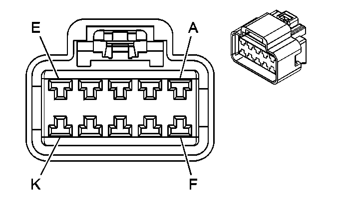
|
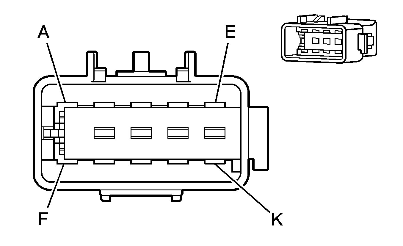
| ||||||||||||||
|---|---|---|---|---|---|---|---|---|---|---|---|---|---|---|---|
Connector Part Information |
| Connector Part Information |
| ||||||||||||
Pin | Wire Color | Circuit No. | Function | Pin | Wire Color | Circuit No. | Function | ||||||||
A | TN | 294 | Door Lock Actuator Unlock Control | A | TN | 294 | Door Lock Actuator Unlock Control | ||||||||
B | GY | 295 | Door Lock Actuator Lock Control | B | GY | 295 | Door Lock Actuator Lock Control | ||||||||
C | PU | 169 | Power Window Master Switch Left Rear Down Signal | C | PU | 169 | Power Window Master Switch Left Rear Down Signal | ||||||||
D | D-GN | 168 | Power Window Master Switch Left Rear Up Signal | D | D-GN | 168 | Power Window Master Switch Left Rear Up Signal | ||||||||
E | YE | 343 | Accessory Voltage | E | YE | 343 | Accessory Voltage | ||||||||
F | PU | 171 | Power Window Master Switch Right Rear Down Signal | F | PU | 171 | Power Window Master Switch Right Rear Down Signal | ||||||||
G | L-GN | 170 | Power Window Master Switch Right Rear Up Signal | G | L-GN | 170 | Power Window Master Switch Right Rear Up Signal | ||||||||
H | BN | 2509 | Left Rear Park Lamps Supply Voltage | H | BN | 2509 | Left Rear Park Lamps Supply Voltage | ||||||||
J | BK | 550 | Ground | J | BK | 550 | Ground | ||||||||
K | PU | 328 | Interior Lamp Defeat Switch Signal/Interior Lamp Switch Signal | K | PU | 328 | Interior Lamp Defeat Switch Signal/Interior Lamp Switch Signal | ||||||||
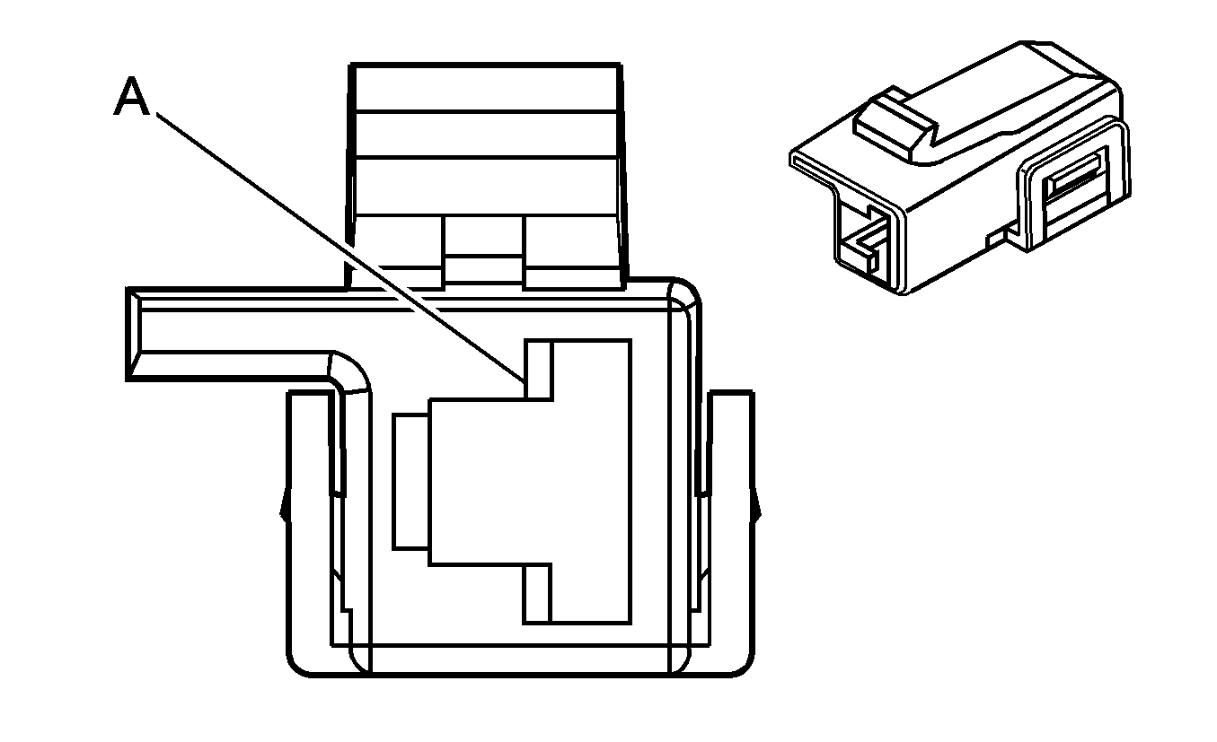
|
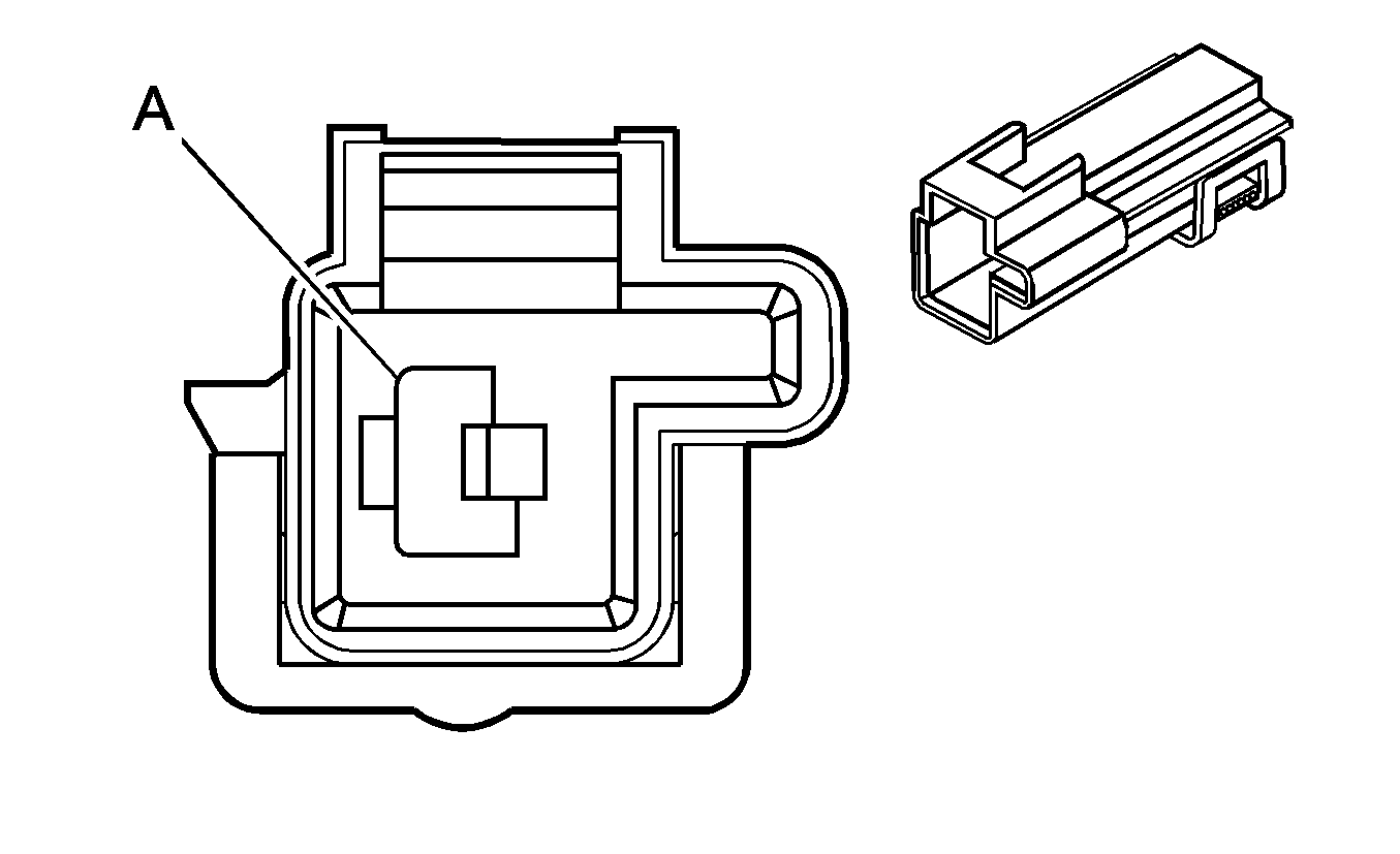
| ||||||||||||||
|---|---|---|---|---|---|---|---|---|---|---|---|---|---|---|---|
Connector Part Information |
| Connector Part Information |
| ||||||||||||
Pin | Wire Color | Circuit No. | Function | Pin | Wire Color | Circuit No. | Function | ||||||||
A | PU | 293 | Rear Defog Element Supply Voltage | A | PU | 293 | Rear Defog Element Supply Voltage | ||||||||
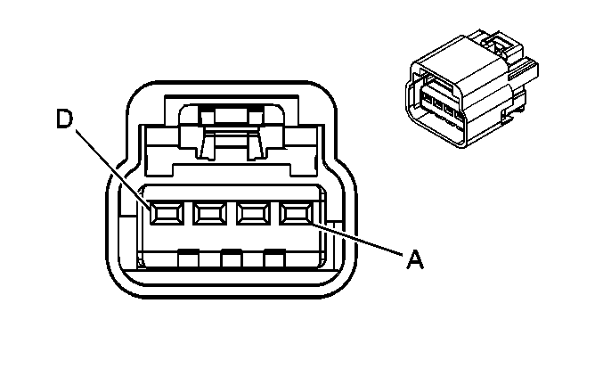
|
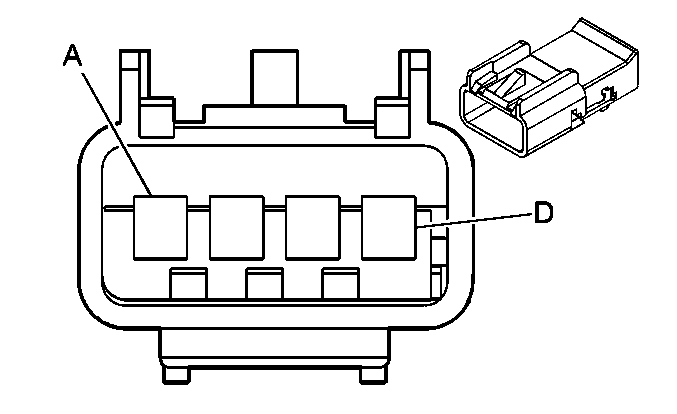
| ||||||||||||||
|---|---|---|---|---|---|---|---|---|---|---|---|---|---|---|---|
Connector Part Information |
| Connector Part Information |
| ||||||||||||
Pin | Wire Color | Circuit No. | Function | Pin | Wire Color | Circuit No. | Function | ||||||||
A | L-BU | 115 | Right Rear Speaker Output (-) | A | L-BU | 115 | Right Rear Speaker Output (-) | ||||||||
B | D-BU | 46 | Right Rear Speaker Output (+) | B | D-BU | 46 | Right Rear Speaker Output (+) | ||||||||
C | YE | 116 | Left Rear Speaker Output (-) | C | YE | 116 | Left Rear Speaker Output (-) | ||||||||
D | BN | 199 | Left Rear Speaker Output (+) | D | BN | 199 | Left Rear Speaker Output (+) | ||||||||

|

| ||||||||||||||
|---|---|---|---|---|---|---|---|---|---|---|---|---|---|---|---|
Connector Part Information |
| Connector Part Information |
| ||||||||||||
Pin | Wire Color | Circuit No. | Function | Pin | Wire Color | Circuit No. | Function | ||||||||
A1 | BK/WH | 746 | Right Front Door Ajar Switch Signal | A1 | BK/WH | 746 | Right Front Door Ajar Switch Signal | ||||||||
A2 | BN | 2509 | Left Rear Park Lamps Supply Voltage (AU0/AU3/A31) | A2 | BN | 2509 | Left Rear Park Lamps Supply Voltage (AU0/AU3/A31) | ||||||||
-- | -- | Not Used (w/o AU0/AU3/A31) | -- | -- | Not Used (w/o AU0/AU3/A31) | ||||||||||
A3 | GY | 157 | Left Speaker Output (+) | A3 | GY | 157 | Left Speaker Output (+) | ||||||||
A4 | BK/WH | 1455 | Keyless Entry Program Enable Signal (AU0) | A4 | BK/WH | 1455 | Keyless Entry Program Enable Signal (AU0) | ||||||||
-- | -- | Not Used (w/o AU0) | -- | -- | Not Used (w/o AU0) | ||||||||||
A5 | WH | 156 | Right Speaker Output (-) | A5 | WH | 156 | Right Speaker Output (-) | ||||||||
A6 | OG | 267 | Heated Mirror Supply Voltage (DB6/DB8) | A6 | OG | 267 | Heated Mirror Supply Voltage (DB6/DB8) | ||||||||
-- | -- | Not Used (w/o DB6/DB8) | -- | -- | Not Used (w/o DB6/DB8) | ||||||||||
A7 | D-GN | 21 | Marker Lamps Supply Voltage (DB6/DB7) | A7 | D-GN | 21 | Marker Lamps Supply Voltage (DB6/DB7) | ||||||||
-- | -- | Not Used (w/o DB6/DB7) | -- | -- | Not Used (w/o DB6/DB7) | ||||||||||
A8 | YE | 343 | Accessory Voltage (AU0/AU3) | A8 | YE | 343 | Accessory Voltage (AU0/AU3) | ||||||||
-- | -- | Not Used (w/o AU0/AU3) | -- | -- | Not Used (w/o AU0/AU3) | ||||||||||
A9 | OG | 540 | Battery Positive Voltage | A9 | OG | 540 | Battery Positive Voltage | ||||||||
A10 | PK | 39 | Ignition 1 Voltage (AU0/AU3) | A10 | PK | 39 | Ignition 1 Voltage (AU0/AU3) | ||||||||
-- | -- | Not Used (w/o AU0/AU3) | -- | -- | Not Used (w/o AU0/AU3) | ||||||||||
A11 | BN/WH | 379 | CPP Switch Signal (Manual Transmission) | A11 | BN/WH | 379 | CPP Switch Signal (Manual Transmission) | ||||||||
-- | -- | Not Used (A/T) | -- | -- | Not Used (A/T) | ||||||||||
A12 | GY | 118 | Left Front Speaker Output (-) | A12 | GY | 118 | Left Front Speaker Output (-) | ||||||||
A13 | TN | 201 | Left Front Speaker Output (+) | A13 | TN | 201 | Left Front Speaker Output (+) | ||||||||
A14 | D-GN | 117 | Right Front Speaker Output (-) | A14 | D-GN | 117 | Right Front Speaker Output (-) | ||||||||
A15 | L-GN | 200 | Right Front Speaker Output (+) | A15 | L-GN | 200 | Right Front Speaker Output (+) | ||||||||
B1 | PU | 328 | Interior Lamp Defeat Switch Signal | B1 | PU | 328 | Interior Lamp Defeat Switch Signal | ||||||||
B2 | TN | 159 | Key Out Ignition Switch Signal | B2 | TN | 159 | Key Out Ignition Switch Signal | ||||||||
B3 | GY | 295 | Door Lock Actuator Lock Control (AU0/AU3) | B3 | GY | 295 | Door Lock Actuator Lock Control (AU0/AU3) | ||||||||
-- | -- | Not Used (w/o AU0/AU3) | -- | -- | Not Used (w/o AU0/AU3) | ||||||||||
B4 | TN | 294 | Door Lock Actuator Unlock Control (AU0/AU3) | B4 | TN | 294 | Door Lock Actuator Unlock Control (AU0/AU3) | ||||||||
-- | -- | Not Used (w/o AU0/AU3) | -- | -- | Not Used (w/o AU0/AU3) | ||||||||||
B5 | BN | 441 | Ignition 3 Voltage | B5 | BN | 441 | Ignition 3 Voltage | ||||||||
B6 | PU | 420 | TCC Brake Switch/Cruise Control Release Signal | B6 | PU | 420 | TCC Brake Switch/Cruise Control Release Signal | ||||||||
B7 | WH | 17 | Stop Lamp Switch Signal | B7 | WH | 17 | Stop Lamp Switch Signal | ||||||||
B8 | OG | 140 | Battery Positive Voltage | B8 | OG | 140 | Battery Positive Voltage | ||||||||
B9 | D-GN | 1433 | PNP/Clutch Start Switch Signal | B9 | D-GN | 1433 | PNP/Clutch Start Switch Signal | ||||||||
B10 | BN | 441 | Ignition 3 Voltage | B10 | BN | 441 | Ignition 3 Voltage | ||||||||
B11 | -- | -- | Not Used | B11 | -- | -- | Not Used | ||||||||
B12 | PU | 806 | Crank Voltage | B12 | PU | 806 | Crank Voltage | ||||||||
B13 | BN | 86 | Cruise Control Release Signal | B13 | BN | 86 | Cruise Control Release Signal | ||||||||
B14 | BK/WH | 451 | Ground | B14 | BK/WH | 451 | Ground | ||||||||
B15 | BK | 28 | Horn Relay Control | B15 | BK | 28 | Horn Relay Control | ||||||||
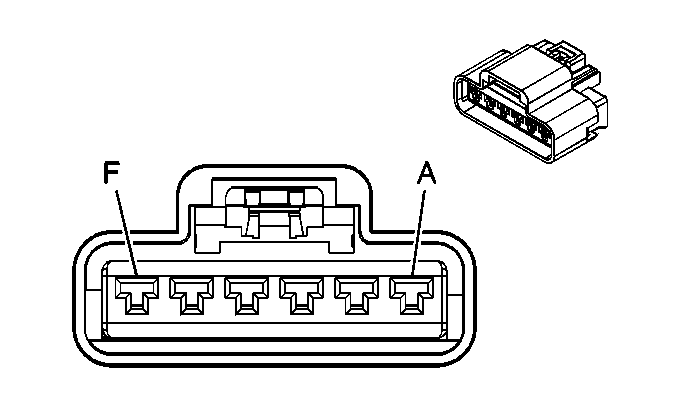
|
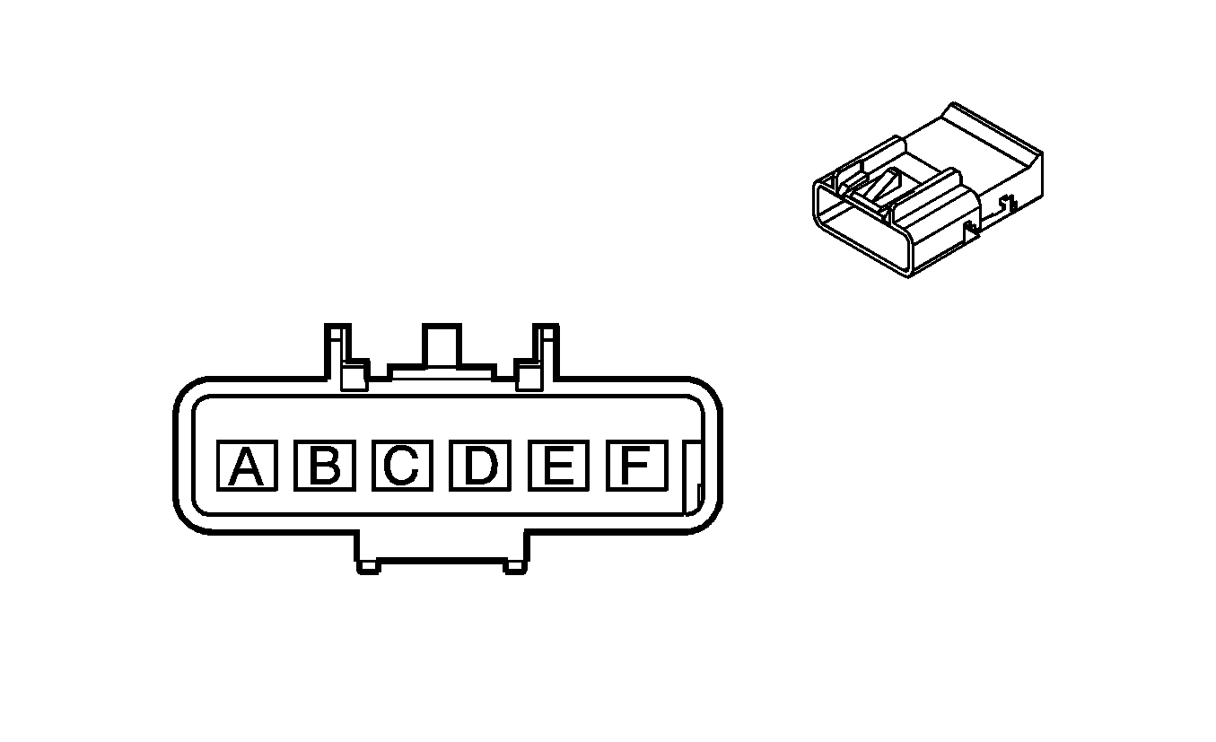
| ||||||||||||||
|---|---|---|---|---|---|---|---|---|---|---|---|---|---|---|---|
Connector Part Information |
| Connector Part Information |
| ||||||||||||
Pin | Wire Color | Circuit No. | Function | Pin | Wire Color | Circuit No. | Function | ||||||||
A | OG | 140 | Battery Positive Voltage | A | OG | 140 | Battery Positive Voltage | ||||||||
B | WH | 17 | Stop Lamp Switch Signal | B | WH | 17 | Stop Lamp Switch Signal | ||||||||
C | BN | 441 | Ignition 3 Voltage | C | BN | 441 | Ignition 3 Voltage | ||||||||
D | PU | 420 | TCC Brake Switch/Cruise Control Release Signal | D | PU | 420 | TCC Brake Switch/Cruise Control Release Signal | ||||||||
E | BN | 86 | Cruise Control Release Signal | E | BN | 86 | Cruise Control Release Signal | ||||||||
F | BK/WH | 451 | Ground | F | BK/WH | 451 | Ground | ||||||||
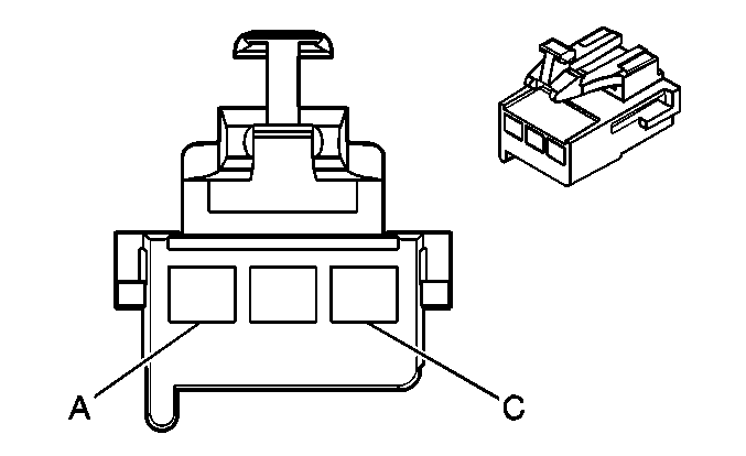
|
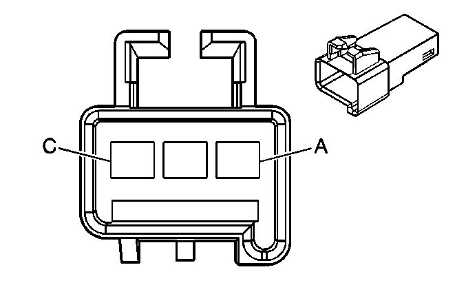
| ||||||||||||||
|---|---|---|---|---|---|---|---|---|---|---|---|---|---|---|---|
Connector Part Information |
| Connector Part Information |
| ||||||||||||
Pin | Wire Color | Circuit No. | Function | Pin | Wire Color | Circuit No. | Function | ||||||||
A | BN | 141 | Ignition 3 Voltage | A | BN | 141 | Ignition 3 Voltage | ||||||||
B | GY | 8 | Instrument Panel Lamp Supply Voltage - 1 | B | GY | 8 | Instrument Panel Lamp Supply Voltage - 1 | ||||||||
C | OG | 540 | Battery Positive Voltage | C | OG | 540 | Battery Positive Voltage | ||||||||
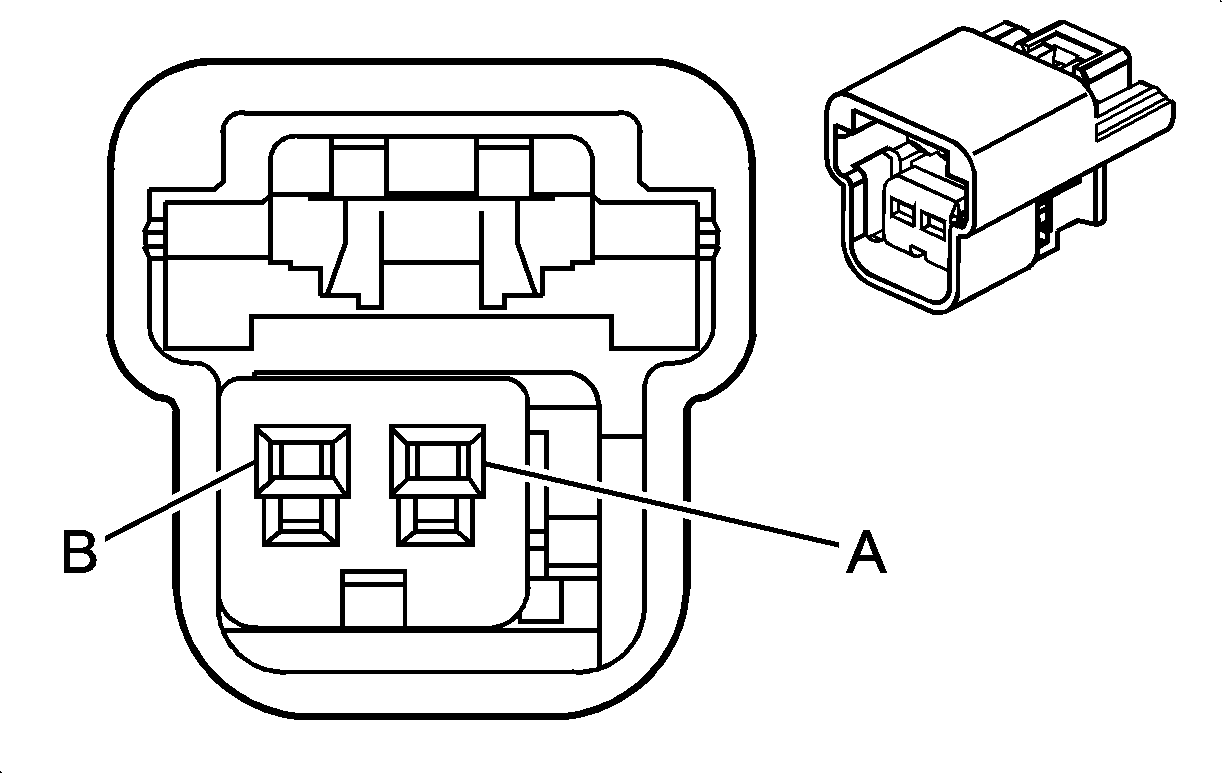
|
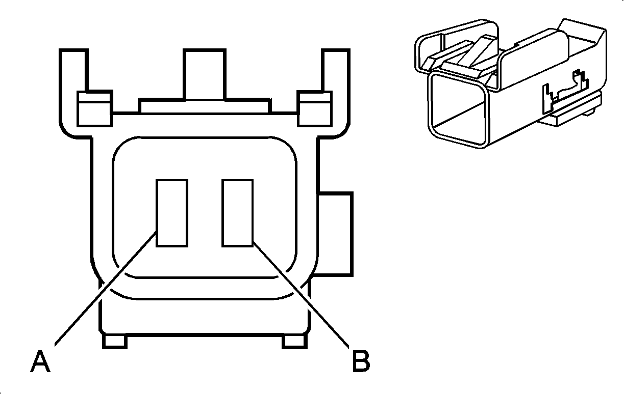
| ||||||||||||||
|---|---|---|---|---|---|---|---|---|---|---|---|---|---|---|---|
Connector Part Information |
| Connector Part Information |
| ||||||||||||
Pin | Wire Color | Circuit No. | Function | Pin | Wire Color | Circuit No. | Function | ||||||||
A | L/BU | 1134 | Park Brake Switch Signal | A | L/BU | 1134 | Park Brake Switch Signal | ||||||||
B | BK | 750 | Ground | B | BK | 750 | Ground | ||||||||
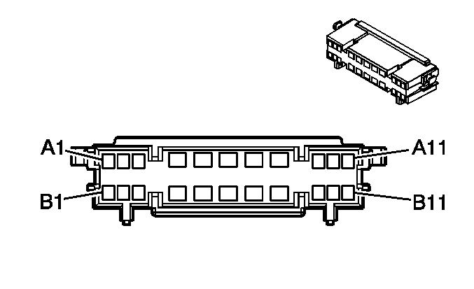
|
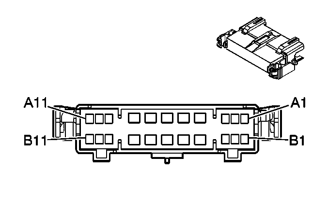
| ||||||||||||||
|---|---|---|---|---|---|---|---|---|---|---|---|---|---|---|---|
Connector Part Information |
| Connector Part Information |
| ||||||||||||
Pin | Wire Color | Circuit No. | Function | Pin | Wire Color | Circuit No. | Function | ||||||||
A1 | BN | 2509 | Left Rear Park Lamps Supply Voltage | A1 | BN | 2509 | Left Rear Park Lamps Supply Voltage | ||||||||
A2 | GY | 118 | Left Front Speaker Output (-) | A2 | GY | 118 | Left Front Speaker Output (-) | ||||||||
A3 | -- | -- | Not Used | A3 | -- | -- | Not Used | ||||||||
A4 | D-GN | 21 | Roof Clearance Lamp Switch Signal | A4 | D-GN | 21 | Roof Clearance Lamp Switch Signal | ||||||||
A5 | YE | 343 | Accessory Voltage | A5 | YE | 343 | Accessory Voltage | ||||||||
A6 | TN | 167 | Power Window Master Switch Right Front Down Signal | A6 | TN | 167 | Power Window Master Switch Right Front Down Signal | ||||||||
A7 | L-BU | 166 | Power Window Master Switch Right Front Up Signal | A7 | L-BU | 166 | Power Window Master Switch Right Front Up Signal | ||||||||
A8 | WH | 194 | Door Unlock Control | A8 | WH | 194 | Door Unlock Control | ||||||||
A9 | OG | 267 | Heated Mirror Supply Voltage | A9 | OG | 267 | Heated Mirror Supply Voltage | ||||||||
A10 | GY | 90 | Passenger Mirror Motor Left Control | A10 | GY | 90 | Passenger Mirror Motor Left Control | ||||||||
A11 | TN | 201 | Left Front Speaker Output (+) | A11 | TN | 201 | Left Front Speaker Output (+) | ||||||||
B1 | PU | 328 | Interior Lamp Defeat Switch Signal/Interior Lamp Switch Signal | B1 | PU | 328 | Interior Lamp Defeat Switch Signal/Interior Lamp Switch Signal | ||||||||
B2 | TN | 159 | Key Out Ignition Switch Signal | B2 | TN | 159 | Key Out Ignition Switch Signal | ||||||||
B3 | BK/WH | 745 | Left Front Door Ajar Switch Signal | B3 | BK/WH | 745 | Left Front Door Ajar Switch Signal | ||||||||
B4 | TN | 294 | Door Lock Actuator Unlock Control | B4 | TN | 294 | Door Lock Actuator Unlock Control | ||||||||
B5 | L-BU | 195 | Door Lock Control | B5 | L-BU | 195 | Door Lock Control | ||||||||
B6 | GY | 295 | Door Lock Actuator Lock Control | B6 | GY | 295 | Door Lock Actuator Lock Control | ||||||||
B7 | YE | 343 | Accessory Voltage | B7 | YE | 343 | Accessory Voltage | ||||||||
B8 | BK | 550 | Ground | B8 | BK | 550 | Ground | ||||||||
B9 | L-BU/WH | 1497 | Passenger Mirror Motor Left/Down Control | B9 | L-BU/WH | 1497 | Passenger Mirror Motor Left/Down Control | ||||||||
B10 | BN/WH | 1498 | Passenger Mirror Motor Up Control | B10 | BN/WH | 1498 | Passenger Mirror Motor Up Control | ||||||||
B11 | OG | 540 | Battery Positive Voltage | B11 | OG | 540 | Battery Positive Voltage | ||||||||

|

| ||||||||||||||
|---|---|---|---|---|---|---|---|---|---|---|---|---|---|---|---|
Connector Part Information |
| Connector Part Information |
| ||||||||||||
Pin | Wire Color | Circuit No. | Function | Pin | Wire Color | Circuit No. | Function | ||||||||
A1 | BN | 2509 | Left Rear Park Lamps Supply Voltage | A1 | BN | 2509 | Left Rear Park Lamps Supply Voltage | ||||||||
A2 | D-GN | 117 | Right Front Speaker Output (-) | A2 | D-GN | 117 | Right Front Speaker Output (-) | ||||||||
A3 | -- | -- | Not Used | A3 | -- | -- | Not Used | ||||||||
A4 | D-GN | 21 | Roof Clearance Lamp Switch Signal | A4 | D-GN | 21 | Roof Clearance Lamp Switch Signal | ||||||||
A5 | YE | 343 | Accessory Voltage | A5 | YE | 343 | Accessory Voltage | ||||||||
A6 | TN | 167 | Power Window Master Switch Right Front Down Signal | A6 | TN | 167 | Power Window Master Switch Right Front Down Signal | ||||||||
A7 | L-BU | 166 | Power Window Master Switch Right Front Up Signal | A7 | L-BU | 166 | Power Window Master Switch Right Front Up Signal | ||||||||
A8 | WH | 194 | Door Unlock Control | A8 | WH | 194 | Door Unlock Control | ||||||||
A9 | OG | 267 | Heated Mirror Supply Voltage | A9 | OG | 267 | Heated Mirror Supply Voltage | ||||||||
A10 | GY | 90 | Passenger Mirror Motor Left Control | A10 | GY | 90 | Passenger Mirror Motor Left Control | ||||||||
A11 | L-GN | 200 | Right Front Speaker Output (+) | A11 | L-GN | 200 | Right Front Speaker Output (+) | ||||||||
B1 | PU | 328 | Interior Lamp Defeat Switch Signal/Interior Lamp Switch Signal | B1 | PU | 328 | Interior Lamp Defeat Switch Signal/Interior Lamp Switch Signal | ||||||||
B2 | -- | -- | Not Used | B2 | -- | -- | Not Used | ||||||||
B3 | BK/WH | 746 | Right Front Door Ajar Switch Signal | B3 | BK/WH | 746 | Right Front Door Ajar Switch Signal | ||||||||
B4 | TN | 294 | Door Lock Actuator Unlock Control | B4 | TN | 294 | Door Lock Actuator Unlock Control | ||||||||
B5 | L-BU | 195 | Door Lock Control | B5 | L-BU | 195 | Door Lock Control | ||||||||
B6 | GY | 295 | Door Lock Actuator Lock Control | B6 | GY | 295 | Door Lock Actuator Lock Control | ||||||||
B7 | -- | -- | Not Used | B7 | -- | -- | Not Used | ||||||||
B8 | BK | 550 | Ground | B8 | BK | 550 | Ground | ||||||||
B9 | L-BU/WH | 1497 | Passenger Mirror Motor Left/Down Control | B9 | L-BU/WH | 1497 | Passenger Mirror Motor Left/Down Control | ||||||||
B10 | BN/WH | 1498 | Passenger Mirror Motor Up Control | B10 | BN/WH | 1498 | Passenger Mirror Motor Up Control | ||||||||
B11 | OG | 540 | Battery Positive Voltage | B11 | OG | 540 | Battery Positive Voltage | ||||||||

|

| ||||||||||||||
|---|---|---|---|---|---|---|---|---|---|---|---|---|---|---|---|
Connector Part Information |
| Connector Part Information |
| ||||||||||||
Pin | Wire Color | Circuit No. | Function | Pin | Wire Color | Circuit No. | Function | ||||||||
A1 | D-GN | 468 | Fuel Injector - Output - Bank 2 | A1 | D-GN | 468 | Fuel Injector - Output - Bank 2 | ||||||||
A2 | PK/BK | 1746 | Fuel Injector 3 Control | A2 | PK/BK | 1746 | Fuel Injector 3 Control | ||||||||
A3 | BK/WH | 845 | Fuel Injector 5 Control | A3 | BK/WH | 845 | Fuel Injector 5 Control | ||||||||
A4-A5 | -- | -- | Not Used | A4-A5 | -- | -- | Not Used | ||||||||
A6 | YE/BK | 846 | Fuel Injector 6 Control | A6 | YE/BK | 846 | Fuel Injector 6 Control | ||||||||
A7 | L-GN/BK | 1745 | Fuel Injector 2 Control | A7 | L-GN/BK | 1745 | Fuel Injector 2 Control | ||||||||
A8 | BK | 1744 | Fuel Injector 1 Control | A8 | BK | 1744 | Fuel Injector 1 Control | ||||||||
B1 | PU | 574 | Low Reference | B1 | PU | 574 | Low Reference | ||||||||
B2 | D-BU | 467 | Fuel Injector - Output - Bank 1 | B2 | D-BU | 467 | Fuel Injector - Output - Bank 1 | ||||||||
B3 | PK | 2677 | Battery Positive Voltage | B3 | PK | 2677 | Battery Positive Voltage | ||||||||
B4 | D-GN/WH | 960 | Low Reference | B4 | D-GN/WH | 960 | Low Reference | ||||||||
B5 | GY | 5481 | Air Heater Enable 1 | B5 | GY | 5481 | Air Heater Enable 1 | ||||||||
B6 | L-BU/BK | 844 | Fuel Injector 4 Control | B6 | L-BU/BK | 844 | Fuel Injector 4 Control | ||||||||
B7 | OG/BK | 726 | 16-Volt Reference | B7 | OG/BK | 726 | 16-Volt Reference | ||||||||
B8 | TN/WH | 332 | Oil Pressure Sensor Signal | B8 | TN/WH | 332 | Oil Pressure Sensor Signal | ||||||||
B9 | GY | 705 | 5-Volt Reference | B9 | GY | 705 | 5-Volt Reference | ||||||||
B10 | L-GN | 36 | Coolant Temperature Signal | B10 | L-GN | 36 | Coolant Temperature Signal | ||||||||
B11 | YE | 1578 | Fuel Temperature Signal | B11 | YE | 1578 | Fuel Temperature Signal | ||||||||
B12 | BK/WH | 851 | Ground | B12 | BK/WH | 851 | Ground | ||||||||
C1 | BK/WH | 51 | Ground | C1 | BK/WH | 51 | Ground | ||||||||
C2 | BN | 1476 | Governor Motor - Return | C2 | BN | 1476 | Governor Motor - Return | ||||||||
C3 | BK/WH | 751 | Ground | C3 | BK/WH | 751 | Ground | ||||||||
C4 | TN | 887 | Fuel Injector Current Sample Signal - Bank 1 | C4 | TN | 887 | Fuel Injector Current Sample Signal - Bank 1 | ||||||||
C5 | D-BU | 888 | Fuel Injector Current Sample Signal - Bank 2 | C5 | D-BU | 888 | Fuel Injector Current Sample Signal - Bank 2 | ||||||||
C6 | YE | 573 | CKP Sensor B Signal | C6 | YE | 573 | CKP Sensor B Signal | ||||||||
C7 | BK/WH | 1251 | Ground | C7 | BK/WH | 1251 | Ground | ||||||||
C8 | D-BU | 467 | Fuel Injector - Output - Bank 1 | C8 | D-BU | 467 | Fuel Injector - Output - Bank 1 | ||||||||
C9 | WH | 1533 | Turbo Boost Pressure Sensor - Signal | C9 | WH | 1533 | Turbo Boost Pressure Sensor - Signal | ||||||||
C10 | BK | 407 | Low Reference | C10 | BK | 407 | Low Reference | ||||||||
C11 | D-BU/WH | 2671 | 5-Volt Reference | C11 | D-BU/WH | 2671 | 5-Volt Reference | ||||||||
C12 | BK/WH | 51 | Ground | C12 | BK/WH | 51 | Ground | ||||||||
D1 | L-GN/BK | 2670 | FRP Sensor Signal | D1 | L-GN/BK | 2670 | FRP Sensor Signal | ||||||||
D2 | BK/WH | 851 | Ground | D2 | BK/WH | 851 | Ground | ||||||||
D3 | D-BU | 1475 | Governor Motor - Feed | D3 | D-BU | 1475 | Governor Motor - Feed | ||||||||
D4-D5 | -- | -- | Not Used | D4-D5 | -- | -- | Not Used | ||||||||
D6 | BK | 470 | Low Reference | D6 | BK | 470 | Low Reference | ||||||||
D7 | D-GN | 468 | Fuel Injector - Output - Bank 2 | D7 | D-GN | 468 | Fuel Injector - Output - Bank 2 | ||||||||
D8 | BN | 1174 | Oil Level Switch Signal | D8 | BN | 1174 | Oil Level Switch Signal | ||||||||
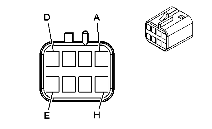
|
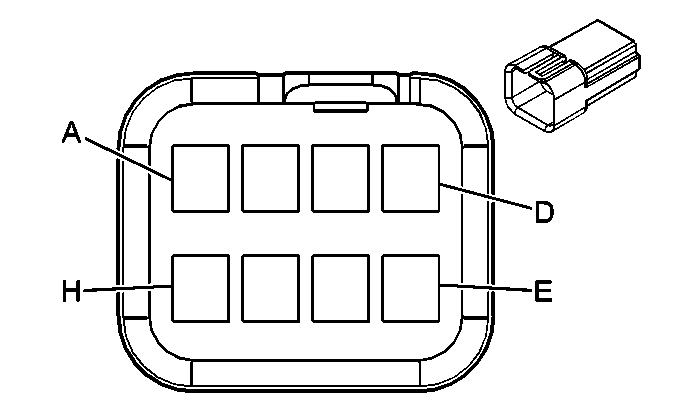
| ||||||||||||||
|---|---|---|---|---|---|---|---|---|---|---|---|---|---|---|---|
Connector Part Information |
| Connector Part Information |
| ||||||||||||
Pin | Wire Color | Circuit No. | Function | Pin | Wire Color | Circuit No. | Function | ||||||||
A | BK | 550 | Ground | A | BK | 550 | Ground | ||||||||
B | BK | 550 | Ground | B | BK | 550 | Ground | ||||||||
C | L-GN | 1499 | Driver Mirror Motor Left/Down Control | C | L-GN | 1499 | Driver Mirror Motor Left/Down Control | ||||||||
D | YE | 1517 | Driver Mirror Switch Up Signal | D | YE | 1517 | Driver Mirror Switch Up Signal | ||||||||
E | -- | -- | Not Used | E | L-GN | 1499 | Driver Mirror Motor Left/Down Control | ||||||||
F | L-BU | 1516 | Driver Mirror Switch Left Signal | F | L-BU | 1516 | Driver Mirror Switch Left Signal | ||||||||
G | D-GN | 21 | Roof Clearance Lamp Switch Signal | G | D-GN | 21 | Roof Clearance Lamp Switch Signal | ||||||||
H | OG | 267 | Heated Mirror Supply Voltage | H | OG | 267 | Heated Mirror Supply Voltage | ||||||||

|

| ||||||||||||||
|---|---|---|---|---|---|---|---|---|---|---|---|---|---|---|---|
Connector Part Information |
| Connector Part Information |
| ||||||||||||
Pin | Wire Color | Circuit No. | Function | Pin | Wire Color | Circuit No. | Function | ||||||||
A | BK | 550 | Ground | A | BK | 550 | Ground | ||||||||
B | BK | 550 | Ground | B | BK | 550 | Ground | ||||||||
C | L-GN | 1499 | Passenger Mirror Motor Left/Down Control | C | L-BU/WH | 1499 | Passenger Mirror Motor Left/Down Control | ||||||||
D | YE | 1517 | Passenger Mirror Switch Up Signal | D | BN/WH | 1517 | Passenger Mirror Switch Up Signal | ||||||||
E | -- | -- | Not Used | E | L-BU/WH | 1499 | Passenger Mirror Motor Left/Down Control | ||||||||
F | L-BU | 1516 | Passenger Mirror Switch Left Signal | F | GY | 1516 | Passenger Mirror Switch Left Signal | ||||||||
G | D-GN | 21 | Roof Clearance Lamp Switch Signal | G | D-GN | 21 | Roof Clearance Lamp Switch Signal | ||||||||
H | OG | 267 | Heated Mirror Supply Voltage | H | OG | 267 | Heated Mirror Supply Voltage | ||||||||
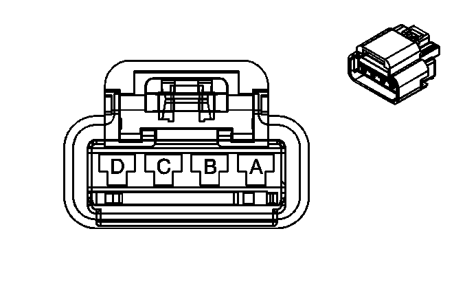
|
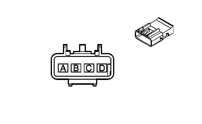
| ||||||||||||||
|---|---|---|---|---|---|---|---|---|---|---|---|---|---|---|---|
Connector Part Information |
| Connector Part Information |
| ||||||||||||
Pin | Wire Color | Circuit No. | Function | Pin | Wire Color | Circuit No. | Function | ||||||||
A | D-GN | 168 | Power Window Master Switch Left Rear Up Signal | A | D-GN | 168 | Power Window Master Switch Left Rear Up Signal | ||||||||
B | PU | 169 | Power Window Master Switch Left Rear Down Signal | B | PU | 169 | Power Window Master Switch Left Rear Down Signal | ||||||||
C | L-GN | 170 | Power Window Master Switch Right Rear Up Signal | C | L-GN | 170 | Power Window Master Switch Right Rear Up Signal | ||||||||
D | PU | 171 | Power Window Master Switch Right Rear Down Signal | D | PU | 171 | Power Window Master Switch Right Rear Down Signal | ||||||||
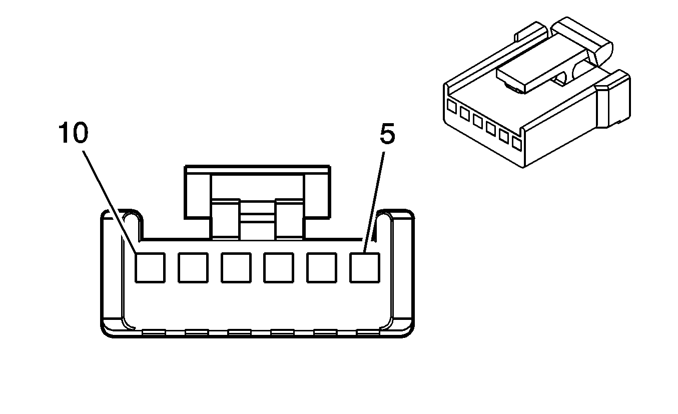
|
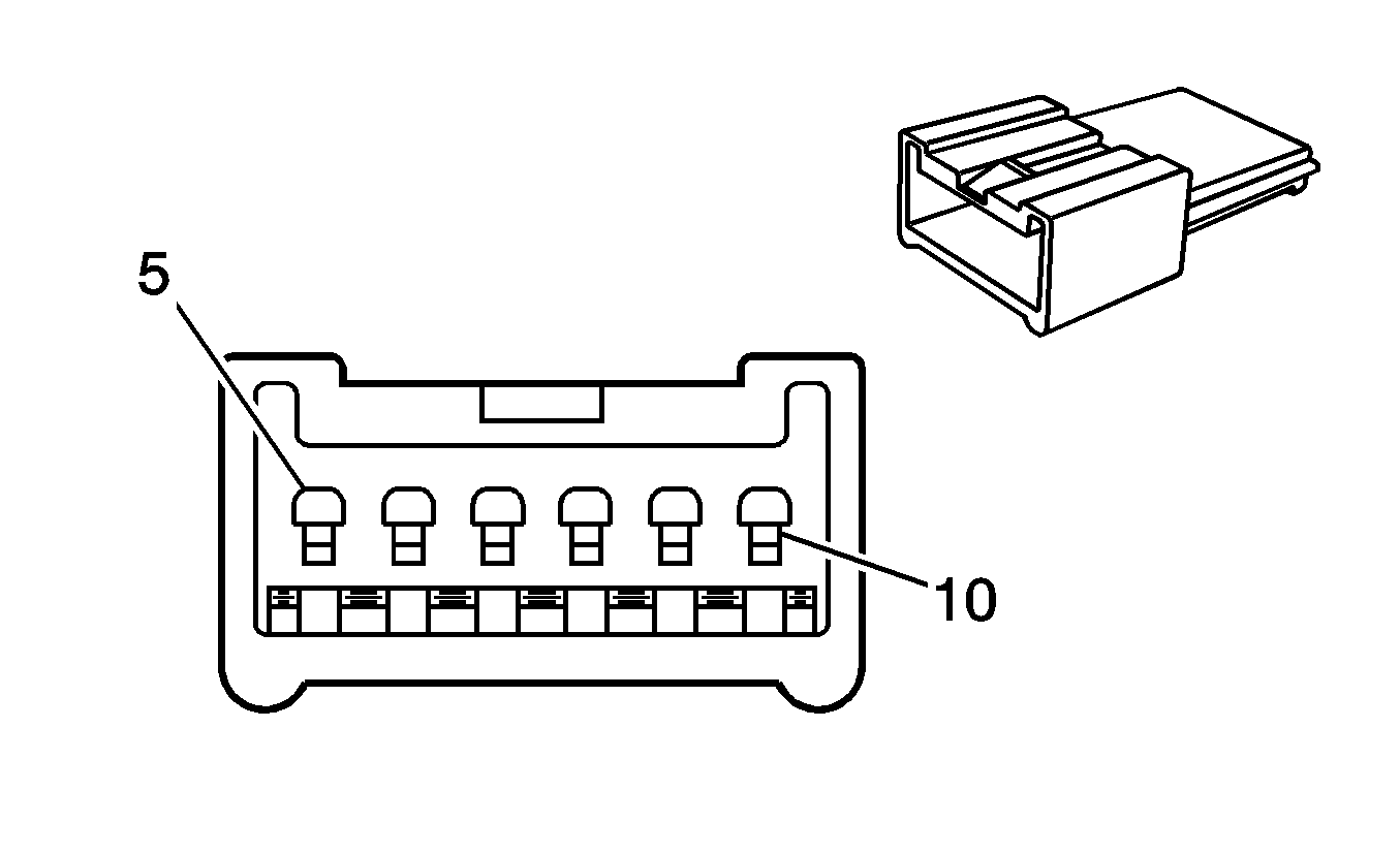
| ||||||||||||||
|---|---|---|---|---|---|---|---|---|---|---|---|---|---|---|---|
Connector Part Information |
| Connector Part Information |
| ||||||||||||
Pin | Wire Color | Circuit No. | Function | Pin | Wire Color | Circuit No. | Function | ||||||||
5-6 | -- | -- | Not Used | 5-6 | -- | -- | Not Used | ||||||||
7 | BK | 450 | Ground | 7 | BK | 450 | Ground | ||||||||
8 | L-BU | 733 | Air Temperature Door Control | 8 | L-BU | 733 | Air Temperature Door Control | ||||||||
9 | -- | -- | Not Used | 9 | -- | -- | Not Used | ||||||||
10 | BN | 141 | Ignition 3 Voltage | 10 | BN | 141 | Ignition 3 Voltage | ||||||||
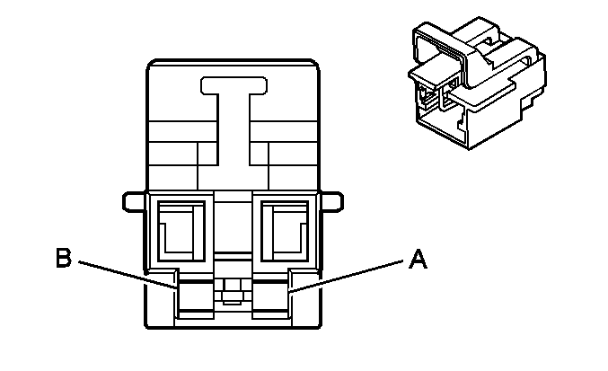
|
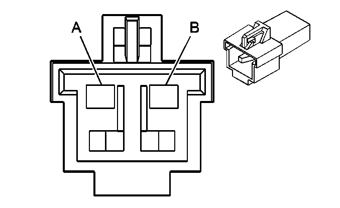
| ||||||||||||||
|---|---|---|---|---|---|---|---|---|---|---|---|---|---|---|---|
Connector Part Information |
| Connector Part Information |
| ||||||||||||
Pin | Wire Color | Circuit No. | Function | Pin | Wire Color | Circuit No. | Function | ||||||||
A | WH | 347 | Steering Wheel Module - High Control | A | WH | 347 | Steering Wheel Module - High Control | ||||||||
B | D-GN | 348 | Steering Wheel Module - Low Control | B | D-GN | 348 | Steering Wheel Module - Low Control | ||||||||

|

| ||||||||||||||
|---|---|---|---|---|---|---|---|---|---|---|---|---|---|---|---|
Connector Part Information |
| Connector Part Information |
| ||||||||||||
Pin | Wire Color | Circuit No. | Function | Pin | Wire Color | Circuit No. | Function | ||||||||
A | L-GN | 24 | Backup Lamp Supply Voltage | A | L-GN | 24 | Backup Lamp Supply Voltage | ||||||||
B | D-GN | 2222 | Signal Low - Rear | B | D-GN | 2222 | Signal Low - Rear | ||||||||
C | L-BU | 2221 | Signal High - Rear | C | L-BU | 2221 | Signal High - Rear | ||||||||
D | GY/BK | 1467 | Shift Motor Relay - Control (HPZ) | D | GY/BK | 1467 | Shift Motor Relay - Control (HPZ) | ||||||||
GY/BK | 1467 | Air Shift Switch Signal (HR1 or HR2) | GY/BK | 1467 | Air Shift Switch Signal (HR1 or HR2) | ||||||||||
E | PK | 139 | Ignition 1 Voltage | E | PK | 139 | Ignition 1 Voltage | ||||||||
F | BK/WH | 451 | Ground | F | BK | 250 | Ground | ||||||||
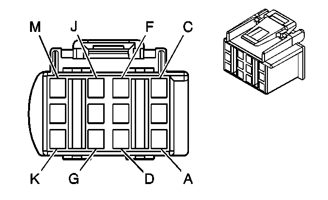
|
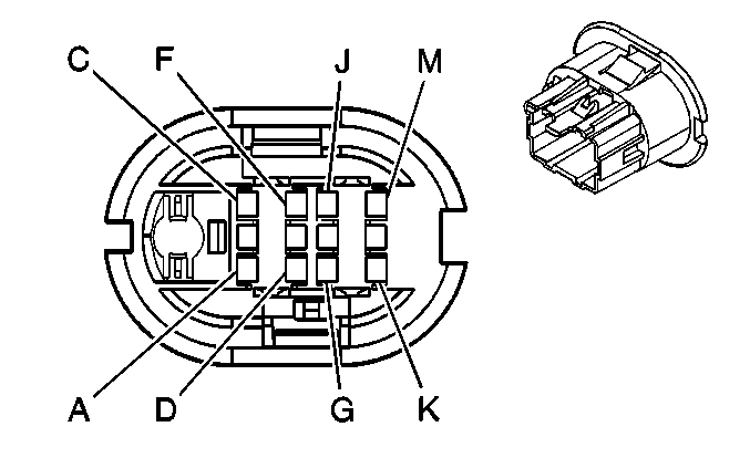
| ||||||||||||||
|---|---|---|---|---|---|---|---|---|---|---|---|---|---|---|---|
Connector Part Information |
| Connector Part Information |
| ||||||||||||
Pin | Wire Color | Circuit No. | Function | Pin | Wire Color | Circuit No. | Function | ||||||||
A | BN | 199 | Left Rear Speaker Output (+) | A | BN | 199 | Left Rear Speaker Output (+) | ||||||||
B | YE | 116 | Left Rear Speaker Output (-) | B | YE | 116 | Left Rear Speaker Output (-) | ||||||||
C | TN | 294 | Door Lock Actuator Unlock Control | C | TN | 294 | Door Lock Actuator Unlock Control | ||||||||
D | GY | 295 | Door Lock Actuator Lock Control | D | GY | 295 | Door Lock Actuator Lock Control | ||||||||
E | D-GN | 168 | Power Window Master Switch Left Rear Up Signal | E | D-GN | 168 | Power Window Master Switch Left Rear Up Signal | ||||||||
F | YE | 343 | Accessory Voltage | F | YE | 343 | Accessory Voltage | ||||||||
G | PU | 169 | Power Window Master Switch Left Rear Down Signal | G | PU | 169 | Power Window Master Switch Left Rear Down Signal | ||||||||
H | BN | 2509 | Left Rear Park Lamps Supply Voltage | H | BN | 2509 | Left Rear Park Lamps Supply Voltage | ||||||||
J | PU | 328 | Interior Lamp Defeat Switch Signal/Interior Lamp Switch Signal | J | PU | 328 | Interior Lamp Defeat Switch Signal/Interior Lamp Switch Signal | ||||||||
K | BK | 550 | Ground | K | BK | 550 | Ground | ||||||||
L-M | -- | -- | Not Used | L-M | -- | -- | Not Used | ||||||||

|

| ||||||||||||||
|---|---|---|---|---|---|---|---|---|---|---|---|---|---|---|---|
Connector Part Information |
| Connector Part Information |
| ||||||||||||
Pin | Wire Color | Circuit No. | Function | Pin | Wire Color | Circuit No. | Function | ||||||||
A | D-BU | 46 | Right Rear Speaker Output (+) | A | D-BU | 46 | Right Rear Speaker Output (+) | ||||||||
B | L-BU | 115 | Right Rear Speaker Output (-) | B | L-BU | 115 | Right Rear Speaker Output (-) | ||||||||
C | TN | 294 | Door Lock Actuator Unlock Control | C | TN | 294 | Door Lock Actuator Unlock Control | ||||||||
D | GY | 295 | Door Lock Actuator Lock Control | D | GY | 295 | Door Lock Actuator Lock Control | ||||||||
E | L-GN | 170 | Power Window Master Switch Right Rear Up Signal | E | L-GN | 170 | Power Window Master Switch Right Rear Up Signal | ||||||||
F | YE | 343 | Accessory Voltage | F | YE | 343 | Accessory Voltage | ||||||||
G | PU | 171 | Power Window Master Switch Right Rear Down Signal | G | PU | 171 | Power Window Master Switch Right Rear Down Signal | ||||||||
H | BN | 2509 | Left Rear Park Lamps Supply Voltage | H | BN | 2509 | Left Rear Park Lamps Supply Voltage | ||||||||
J | PU | 328 | Interior Lamp Defeat Switch Signal/Interior Lamp Switch Signal | J | PU | 328 | Interior Lamp Defeat Switch Signal/Interior Lamp Switch Signal | ||||||||
K | BK | 550 | Ground | K | BK | 550 | Ground | ||||||||
L-M | -- | -- | Not Used | L-M | -- | -- | Not Used | ||||||||
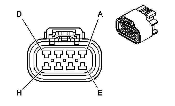
|
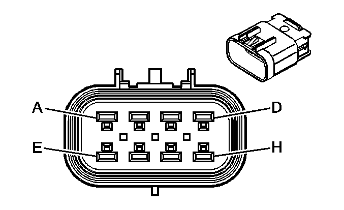
| ||||||||||||||
|---|---|---|---|---|---|---|---|---|---|---|---|---|---|---|---|
Connector Part Information |
| Connector Part Information |
| ||||||||||||
Pin | Wire Color | Circuit No. | Function | Pin | Wire Color | Circuit No. | Function | ||||||||
A | YE | 618 | Left Rear Turn Signal Lamp Supply Voltage | A | YE | 618 | Left Rear Turn Signal Lamp Supply Voltage | ||||||||
B | BN | 2509 | Left Rear Park Lamps Supply Voltage | B | BN | 2509 | Left Rear Park Lamps Supply Voltage | ||||||||
C | -- | -- | Not Used | C | -- | -- | Not Used | ||||||||
D | BN/WH | 2609 | Right Rear Park Lamps Supply Voltage | D | BN/WH | 2609 | Right Rear Park Lamps Supply Voltage | ||||||||
E | D-GN | 619 | Right Rear Turn Signal Lamp Supply Voltage | E | D-GN | 619 | Right Rear Turn Signal Lamp Supply Voltage | ||||||||
F | L-GN | 24 | Backup Lamp Supply Voltage | F | L-GN | 24 | Backup Lamp Supply Voltage | ||||||||
G | BK | 350 | Ground | G | BK | 350 | Ground | ||||||||
H | -- | -- | Not Used | H | -- | -- | Not Used | ||||||||
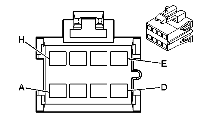
|
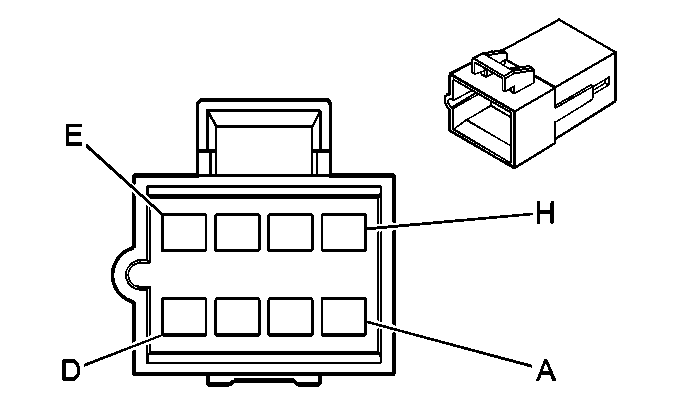
| ||||||||||||||
|---|---|---|---|---|---|---|---|---|---|---|---|---|---|---|---|
Connector Part Information |
| Connector Part Information |
| ||||||||||||
Pin | Wire Color | Circuit No. | Function | Pin | Wire Color | Circuit No. | Function | ||||||||
A | D-BU | 1413 | ABS Enable Relay - Contact - N.O. | A | D-BU | 1413 | ABS Enable Relay - Contact - N.O. | ||||||||
B | BN | 9 | Park Lamp Supply Voltage | B | BN | 9 | Park Lamp Supply Voltage | ||||||||
C | D-GN | 319 | Right Rear Trailer Stop/Turn Lamp Supply Voltage | C | D-GN | 319 | Right Rear Trailer Stop/Turn Lamp Supply Voltage | ||||||||
D | RD | 1411 | Trailer Stop Relay - Contact - N.O. | D | RD | 1411 | Trailer Stop Relay - Contact - N.O. | ||||||||
E | YE | 318 | Left Rear Trailer Stop/Turn Lamp Supply Voltage | E | YE | 318 | Left Rear Trailer Stop/Turn Lamp Supply Voltage | ||||||||
F | BK | 1412 | Marker Lamp Supply Voltage | F | BK | 1412 | Marker Lamp Supply Voltage | ||||||||
G | WH | 17 | Stop Lamp Switch Signal | G | WH | 17 | Stop Lamp Switch Signal | ||||||||
H | OG | 140 | Battery Positive Voltage | H | OG | 140 | Battery Positive Voltage | ||||||||

|

| ||||||||||||||
|---|---|---|---|---|---|---|---|---|---|---|---|---|---|---|---|
Connector Part Information |
| Connector Part Information |
| ||||||||||||
Pin | Wire Color | Circuit No. | Function | Pin | Wire Color | Circuit No. | Function | ||||||||
A | YE/BK | 1827 | Vehicle Speed Signal | A | -- | -- | Upfitter Usage | ||||||||
B | BN/WH | 2609 | Park Lamps Supply Voltage | B | -- | -- | Upfitter Usage | ||||||||
C | YE | 318 | Left Rear Trailer Stop/Turn Lamp Supply Voltage | C | -- | -- | Upfitter Usage | ||||||||
D | BN | 2509 | Left Rear Park Lamps Supply Voltage | D | -- | -- | Upfitter Usage | ||||||||
E | L-BU | 1320 | Stop Lamp Supply Voltage | E | -- | -- | Upfitter Usage | ||||||||
F | BN | 641 | Ignition 3 Voltage | F | -- | -- | Upfitter Usage | ||||||||
G | D-GN | 21 | Marker Lamps Supply Voltage | G | -- | -- | Upfitter Usage | ||||||||
H | BK | 350 | Ground | H | -- | -- | Upfitter Usage | ||||||||
J | -- | -- | Not Used | J | -- | -- | Upfitter Usage | ||||||||
K | D-GN | 319 | Right Rear Trailer Stop/Turn Lamp Supply Voltage | K | -- | -- | Upfitter Usage | ||||||||
L | L-GN | 24 | Backup Lamp Supply Voltage | L | -- | -- | Upfitter Usage | ||||||||
M | -- | -- | Not Used | M | -- | -- | Upfitter Usage | ||||||||
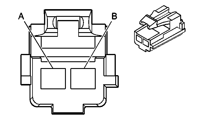
|
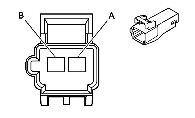
| ||||||||||||||
|---|---|---|---|---|---|---|---|---|---|---|---|---|---|---|---|
Connector Part Information |
| Connector Part Information |
| ||||||||||||
Pin | Wire Color | Circuit No. | Function | Pin | Wire Color | Circuit No. | Function | ||||||||
A | OG | 840 | Battery Positive Voltage | A | OG | 840 | Battery Positive Voltage | ||||||||
B | BK | 750 | Ground | B | BK | 750 | Ground | ||||||||
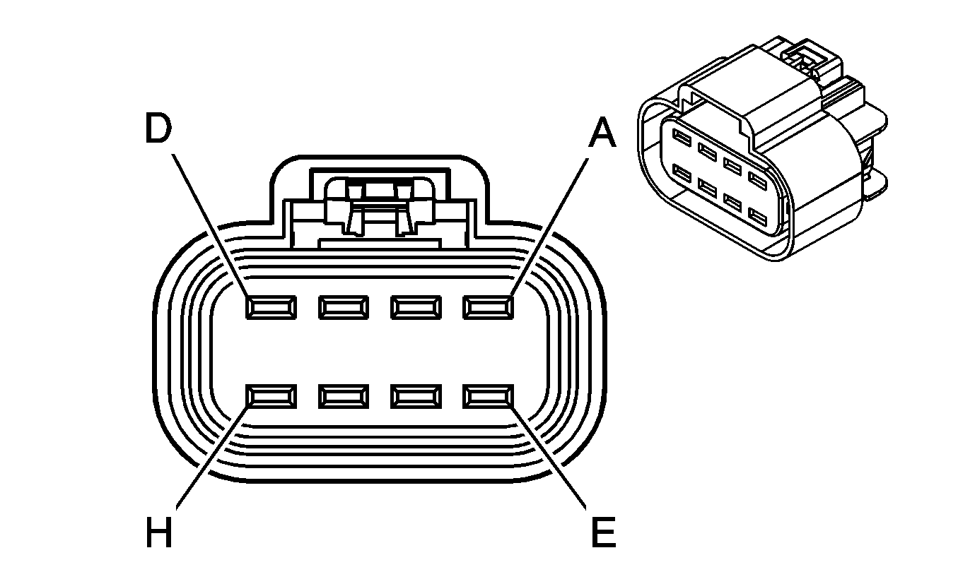
|

| ||||||||||||||
|---|---|---|---|---|---|---|---|---|---|---|---|---|---|---|---|
Connector Part Information |
| Connector Part Information |
| ||||||||||||
Pin | Wire Color | Circuit No. | Function | Pin | Wire Color | Circuit No. | Function | ||||||||
A | GY/BK | 1467 | Shift Motor Relay - Control (HPZ) | A | GY/BK | 1467 | Shift Motor Relay - Control (HPZ) | ||||||||
GY/BK | 1467 | Air Shift Switch Signal (HR1 or HR2) | GY/BK | 1467 | Air Shift Switch Signal (HR1 or HR2) | ||||||||||
B | -- | -- | Not Used | B | -- | -- | Not Used | ||||||||
C | D-BU/WH | 1911 | Left Rear Wheel Speed Sensor Signal | C | D-BU/WH | 1911 | Left Rear Wheel Speed Sensor Signal | ||||||||
D | BK | 350 | Ground | D | BK | 350 | Ground | ||||||||
E | D-GN/WH | 1912 | Left Rear Wheel Speed Sensor Low Reference | E | D-GN/WH | 1912 | Left Rear Wheel Speed Sensor Low Reference | ||||||||
F | BK | 250 | Ground | F | BK | 250 | Ground | ||||||||
G | BN | 241 | Ignition 3 Voltage | G | BN | 241 | Ignition 3 Voltage | ||||||||
H | D-BU | 1944 | Suspension Dump Valve Solenoid Control | H | D-BU | 1944 | Suspension Dump Valve Solenoid Control | ||||||||
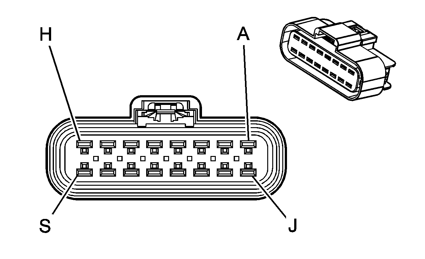
|
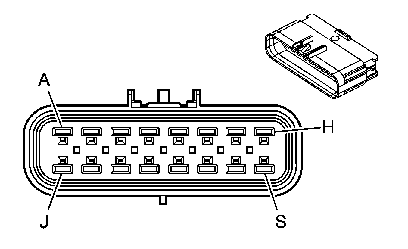
| ||||||||||||||
|---|---|---|---|---|---|---|---|---|---|---|---|---|---|---|---|
Connector Part Information |
| Connector Part Information |
| ||||||||||||
Pin | Wire Color | Circuit No. | Function | Pin | Wire Color | Circuit No. | Function | ||||||||
A | L-GN/WH | 1918 | Right Rear Modulator Exhaust Control | A | L-GN/WH | 1918 | Right Rear Modulator Exhaust Control | ||||||||
B | PU | 1920 | Right Rear Modulator Supply Voltage | B | PU | 1920 | Right Rear Modulator Supply Voltage | ||||||||
C | PK/BK | 1919 | Right Rear Modulator Hold Control | C | PK/BK | 1919 | Right Rear Modulator Hold Control | ||||||||
D | GY/BK | 1913 | Left Rear Modulator Supply Voltage | D | GY/BK | 1913 | Left Rear Modulator Supply Voltage | ||||||||
E | PK | 2668 | Traction Control Valve (Air) Hi | E | PK | 2668 | Traction Control Valve (Air) Hi | ||||||||
F | BK | 250 | Ground | F | BK | 250 | Ground | ||||||||
G | PK/WH | 2669 | Traction Control Valve (Air) Lo | G | PK/WH | 2669 | Traction Control Valve (Air) Lo | ||||||||
H | D-BU | 1944 | Suspension Dump Valve Solenoid Control | H | D-BU | 1944 | Suspension Dump Valve Solenoid Control | ||||||||
J | L-BU/BK | 1914 | Left Rear Modulator Hold control | J | L-BU/BK | 1914 | Left Rear Modulator Hold control | ||||||||
K | OG | 1915 | Left Rear Modulator Supply Voltage | K | OG | 1915 | Left Rear Modulator Supply Voltage | ||||||||
L | D-BU/WH | 1911 | Left Rear Wheel Speed Sensor Signal | L | D-BU/WH | 1911 | Left Rear Wheel Speed Sensor Signal | ||||||||
M | D-GN/WH | 1912 | Left Rear Wheel Speed Sensor Low Reference | M | D-GN/WH | 1912 | Left Rear Wheel Speed Sensor Low Reference | ||||||||
N | -- | -- | Not Used | N | -- | -- | Not Used | ||||||||
P | GY/BK | 1467 | Shift Motor Relay - Control (HPZ) | P | GY/BK | 1467 | Shift Motor Relay - Control (HPZ) | ||||||||
GY/BK | 1467 | Air Shift Switch Signal (HR1 or HR2) | GY/BK | 1467 | Air Shift Switch Signal (HR1 or HR2) | ||||||||||
R | BN | 241 | Ignition 3 Voltage | R | BN | 241 | Ignition 3 Voltage | ||||||||
S | BK | 350 | Ground | S | BK | 350 | Ground | ||||||||
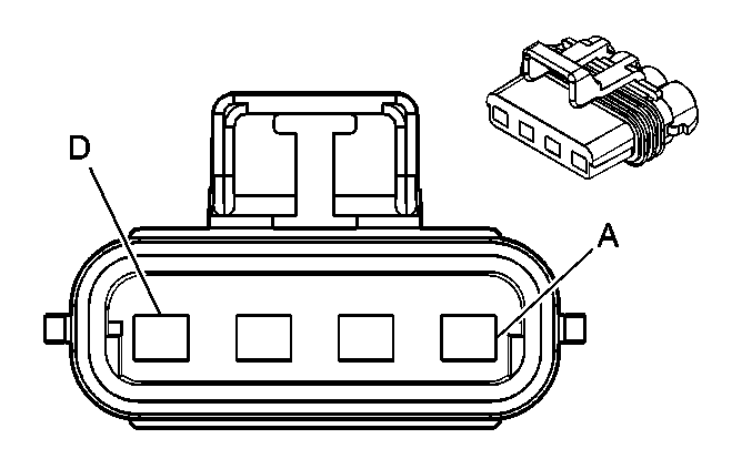
|
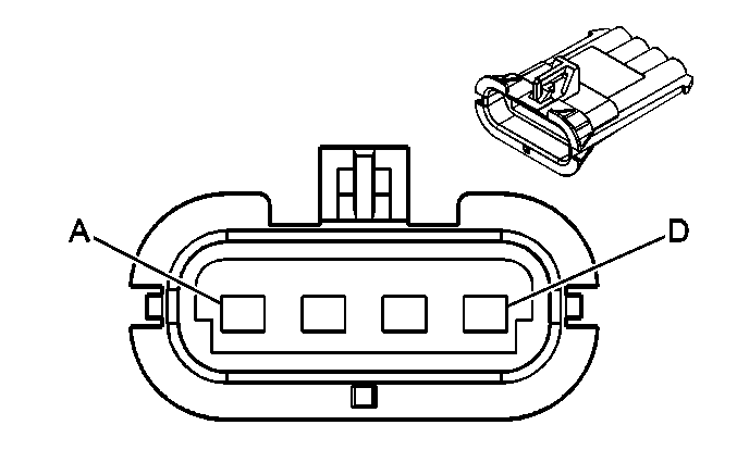
| ||||||||||||||
|---|---|---|---|---|---|---|---|---|---|---|---|---|---|---|---|
Connector Part Information |
| Connector Part Information |
| ||||||||||||
Pin | Wire Color | Circuit No. | Function | Pin | Wire Color | Circuit No. | Function | ||||||||
A | GY/BK | 1467 | Shift Motor Relay - Control (HPZ) | A | GY/BK | 1467 | Shift Motor Relay - Control (HPZ) | ||||||||
GY/BK | 1467 | Air Shift Switch Signal (HR1 or HR2) | GY/BK | 1467 | Air Shift Switch Signal (HR1 or HR2) | ||||||||||
B | BN | 241 | Ignition 3 Voltage (HPZ) | B | BN | 241 | Ignition 3 Voltage (HPZ) | ||||||||
-- | -- | Not Used (HR1 or HR2) | -- | -- | Not Used (HR1 or HR2) | ||||||||||
C | BK | 350 | Ground (HPZ) | C | BK | 350 | Ground (HPZ) | ||||||||
-- | -- | Not Used (HR1 or HR2) | -- | -- | Not Used (HR1 or HR2) | ||||||||||
D | BK | 250 | Ground (HR1 or HR2) | D | BK | 250 | Ground (HR1 or HR2) | ||||||||
-- | -- | Not Used (HPZ) | -- | -- | Not Used (HPZ) | ||||||||||

|

| ||||||||||||||
|---|---|---|---|---|---|---|---|---|---|---|---|---|---|---|---|
Connector Part Information |
| Connector Part Information |
| ||||||||||||
Pin | Wire Color | Circuit No. | Function | Pin | Wire Color | Circuit No. | Function | ||||||||
A | TN | 1465 | Fuel Pump Relay Control - Secondary (L18) | A | TN | 1465 | Fuel Pump Relay Control - Secondary | ||||||||
-- | -- | Not Used (LLY) | |||||||||||||
B | BK | 470 | Low Reference | B | BK | 470 | Low Reference | ||||||||
C | PU | 1589 | Fuel Level Sensor Signal - Primary | C | PU | 1589 | Fuel Level Sensor Signal - Primary | ||||||||
D | D-BU | 1936 | Fuel Level Sensor Signal - Secondary | D | D-BU | 1936 | Fuel Level Sensor Signal - Secondary (LLY) | ||||||||
E | -- | -- | Not Used | E | -- | -- | Not Used | ||||||||
F | GY | 120 | Fuel Pump Supply Voltage | F | GY | 120 | Fuel Pump Supply Voltage | ||||||||
G | D-BU/WH | 1911 | Left Rear Wheel Speed Sensor Signal | G | D-BU/WH | 1911 | Left Rear Wheel Speed Sensor Signal | ||||||||
H | D-GN/WH | 1912 | Left Rear Wheel Speed Sensor Low Reference | H | D-GN/WH | 1912 | Left Rear Wheel Speed Sensor Low Reference | ||||||||
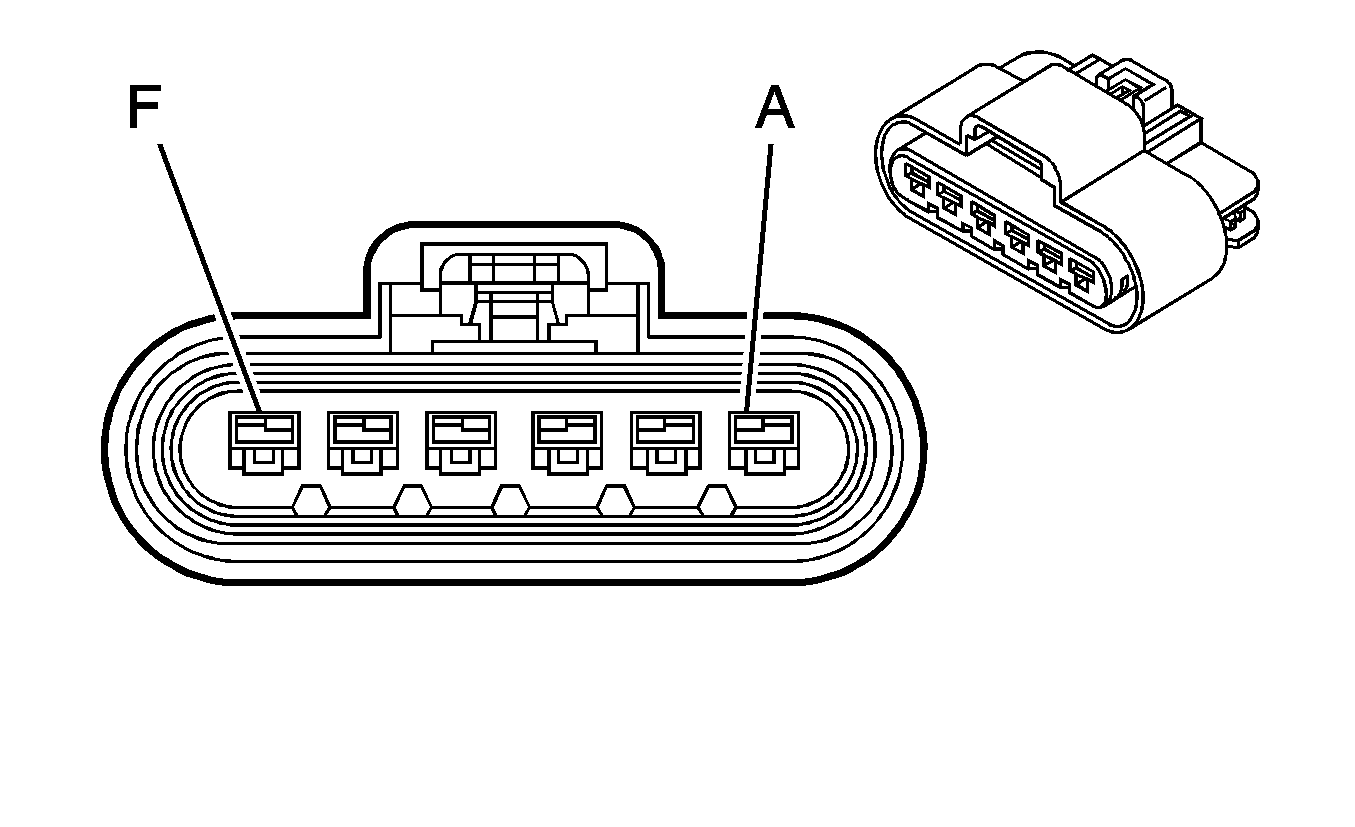
|

| ||||||||||||||
|---|---|---|---|---|---|---|---|---|---|---|---|---|---|---|---|
Connector Part Information |
| Connector Part Information |
| ||||||||||||
Pin | Wire Color | Circuit No. | Function | Pin | Wire Color | Circuit No. | Function | ||||||||
A | TN | 1465 | Fuel Pump Relay Control - Secondary (L18 w/Dual Tanks) | A | TN | 1465 | Fuel Pump Relay Control - Secondary (L18 w/Dual Tanks) | ||||||||
B | BK | 470 | Low Reference | B | BK | 470 | Low Reference | ||||||||
C | PU | 1589 | Fuel Level Sensor Signal - Primary | C | PU | 1589 | Fuel Level Sensor Signal - Primary | ||||||||
D | D-BU | 1936 | Fuel Level Sensor Signal - Secondary (w/Dual Tanks) | D | D-BU | 1936 | Fuel Level Sensor Signal - Secondary (w/Dual Tanks) | ||||||||
E | -- | -- | Not Used | E | -- | -- | Not Used | ||||||||
F | GY | 120 | Fuel Pump Supply Voltage | F | GY | 120 | Fuel Pump Supply Voltage | ||||||||

|

| ||||||||||||||
|---|---|---|---|---|---|---|---|---|---|---|---|---|---|---|---|
Connector Part Information |
| Connector Part Information |
| ||||||||||||
Pin | Wire Color | Circuit No. | Function | Pin | Wire Color | Circuit No. | Function | ||||||||
A | OG | 1840 | Battery Positive Voltage | A | OG | 1840 | Battery Positive Voltage | ||||||||
B | GY | 541 | Ignition 3 Voltage | B | RD | 541 | Ignition 3 Voltage | ||||||||
C | BK | 350 | Ground | C | BK | 350 | Ground | ||||||||

|

| ||||||||||||||
|---|---|---|---|---|---|---|---|---|---|---|---|---|---|---|---|
Connector Part Information |
| Connector Part Information |
| ||||||||||||
Pin | Wire Color | Circuit No. | Function | Pin | Wire Color | Circuit No. | Function | ||||||||
A | YE | 618 | Left Rear Turn Signal Lamp Supply Voltage | A | YE | 618 | Left Rear Turn Signal Lamp Supply Voltage | ||||||||
B | BN | 2509 | Left Rear Park Lamps Supply Voltage | B | BN | 2509 | Left Rear Park Lamps Supply Voltage | ||||||||
C | -- | -- | Not Used | C | -- | -- | Not Used | ||||||||
D | BN/WH | 2609 | Right Rear Park Lamps Supply Voltage | D | BN/WH | 2609 | Right Rear Park Lamps Supply Voltage | ||||||||
E | D-GN | 619 | Right Rear Turn Signal Lamp Supply Voltage | E | D-GN | 619 | Right Rear Turn Signal Lamp Supply Voltage | ||||||||
F | L-GN | 24 | Backup Lamp Supply Voltage | F | L-GN | 24 | Backup Lamp Supply Voltage | ||||||||
G | BK | 350 | Ground | G | BK | 350 | Ground | ||||||||
H | -- | -- | Not Used | H | -- | -- | Not Used | ||||||||

|

| ||||||||||||||
|---|---|---|---|---|---|---|---|---|---|---|---|---|---|---|---|
Connector Part Information |
| Connector Part Information |
| ||||||||||||
Pin | Wire Color | Circuit No. | Function | Pin | Wire Color | Circuit No. | Function | ||||||||
A | YE | 618 | Left Rear Turn Signal Lamp Supply Voltage | A | YE | 618 | Left Rear Turn Signal Lamp Supply Voltage | ||||||||
B | BN | 2509 | Left Rear Park Lamps Supply Voltage | B | BN | 2509 | Left Rear Park Lamps Supply Voltage | ||||||||
C | -- | -- | Not Used | C | -- | -- | Not Used | ||||||||
D | BN/WH | 2609 | Right Rear Park Lamps Supply Voltage | D | BN/WH | 2609 | Right Rear Park Lamps Supply Voltage | ||||||||
E | D-GN | 619 | Right Rear Turn Signal Lamp Supply Voltage | E | D-GN | 619 | Right Rear Turn Signal Lamp Supply Voltage | ||||||||
F | L-GN | 24 | Backup Lamp Supply Voltage | F | L-GN | 24 | Backup Lamp Supply Voltage | ||||||||
G | BK | 350 | Ground | G | BK | 350 | Ground | ||||||||
H | -- | -- | Not Used | H | -- | -- | Not Used | ||||||||

|

| ||||||||||||||
|---|---|---|---|---|---|---|---|---|---|---|---|---|---|---|---|
Connector Part Information |
| Connector Part Information |
| ||||||||||||
Pin | Wire Color | Circuit No. | Function | Pin | Wire Color | Circuit No. | Function | ||||||||
A | 550 | BK | Ground | A | 550 | BK | Ground | ||||||||
B | 550 | BK | Ground | B | 550 | BK | Ground | ||||||||
C | 1499 | L-GN | Driver Mirror Motor Left/Down Control | C | 1499 | L-GN | Driver Mirror Motor Left/Down Control | ||||||||
D | 1517 | YE | Driver Mirror Switch Up Signal | D | 1517 | YE | Driver Mirror Switch Up Signal | ||||||||
E | -- | -- | Not Used | E | -- | -- | Not Used | ||||||||
F | 1516 | L-BU | Driver Mirror Switch Left Signal | F | 1516 | L-BU | Driver Mirror Switch Left Signal | ||||||||
G | 21 | D-GN | Marker Lamps Supply Voltage | G | 21 | D-GN | Marker Lamps Supply Voltage | ||||||||
H | 267 | OG | Heated Mirror Supply Voltage | H | 267 | OG | Heated Mirror Supply Voltage | ||||||||

|

| ||||||||||||||
|---|---|---|---|---|---|---|---|---|---|---|---|---|---|---|---|
Connector Part Information |
| Connector Part Information |
| ||||||||||||
Pin | Wire Color | Circuit No. | Function | Pin | Wire Color | Circuit No. | Function | ||||||||
A | 550 | BK | Ground | A | 550 | BK | Ground | ||||||||
B | 550 | BK | Ground | B | 550 | BK | Ground | ||||||||
C | 1499 | L-GN | Driver Mirror Motor Left/Down Control | C | 1499 | L-GN | Driver Mirror Motor Left/Down Control | ||||||||
D | 1517 | YE | Driver Mirror Switch Up Signal | D | 1517 | YE | Driver Mirror Switch Up Signal | ||||||||
E | -- | -- | Not Used | E | -- | -- | Not Used | ||||||||
F | 1516 | L-BU | Driver Mirror Switch Left Signal | F | 1516 | L-BU | Driver Mirror Switch Left Signal | ||||||||
G | 21 | D-GN | Marker Lamps Supply Voltage | G | 21 | D-GN | Marker Lamps Supply Voltage | ||||||||
H | 267 | OG | Heated Mirror Supply Voltage | H | 267 | OG | Heated Mirror Supply Voltage | ||||||||
