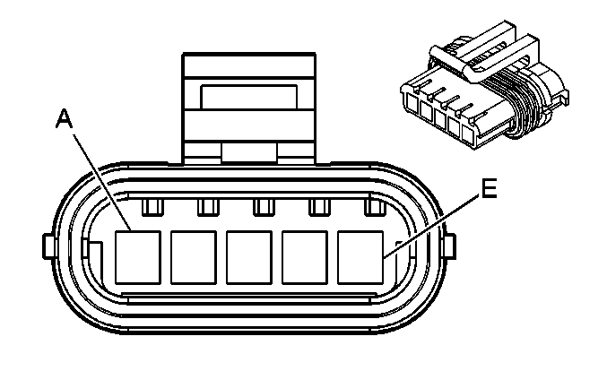
| Table 1: | Accelerator Pedal Position (APP) Sensor |
| Table 2: | Camshaft Position (CMP) Sensor |
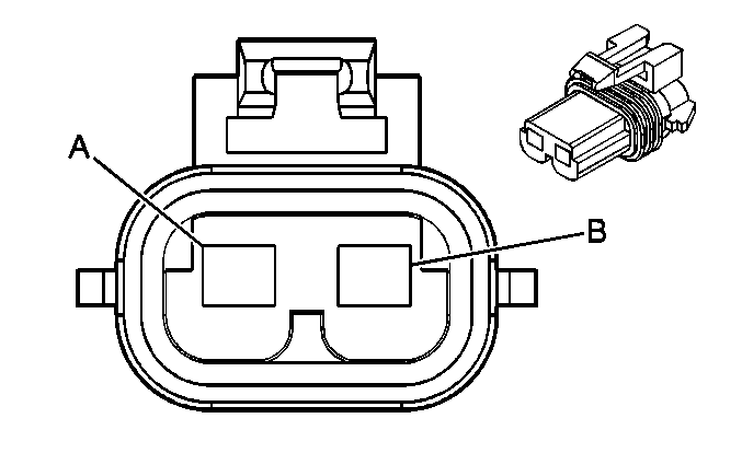
| Table 3: | Canister Purge Solenoid |
| Table 4: | Clutch Switch |
| Table 5: | Coolant Level Switch |
| Table 6: | Crankshaft Position (CKP) Sensor |
| Table 7: | Engine Coolant Temperature (ECT) Switch |
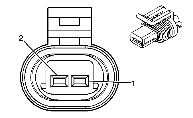
| Table 8: | Engine Oil Pressure (EOP) Sensor |
| Table 9: | Exhaust Gas Recirculation (EGR) Solenoid |
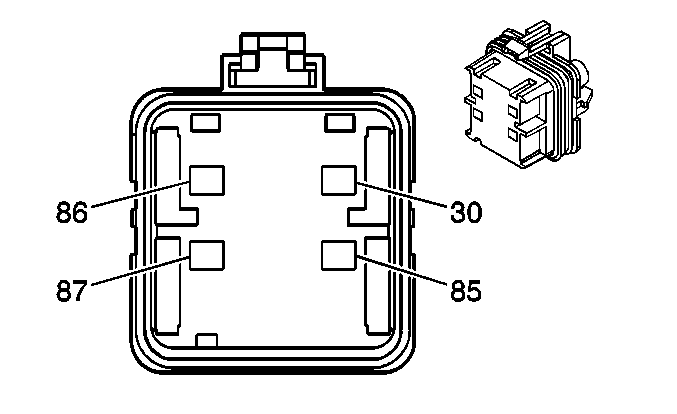
| Table 10: | Fuel Pump Relay-Secondary |
| Table 11: | Fuel Pump Relay-Secondary |
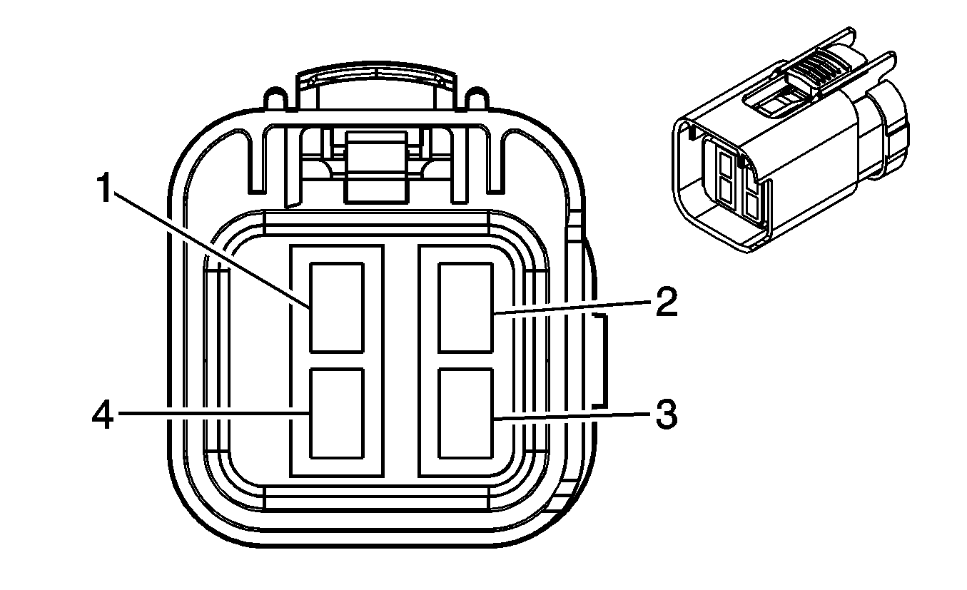
| Table 12: | Fuel Sender-Secondary |
| Table 13: | Heated Oxygen Sensor (H02S) - (LH) |
| Table 14: | Heated Oxygen Sensor (HO2S) - (RH) |
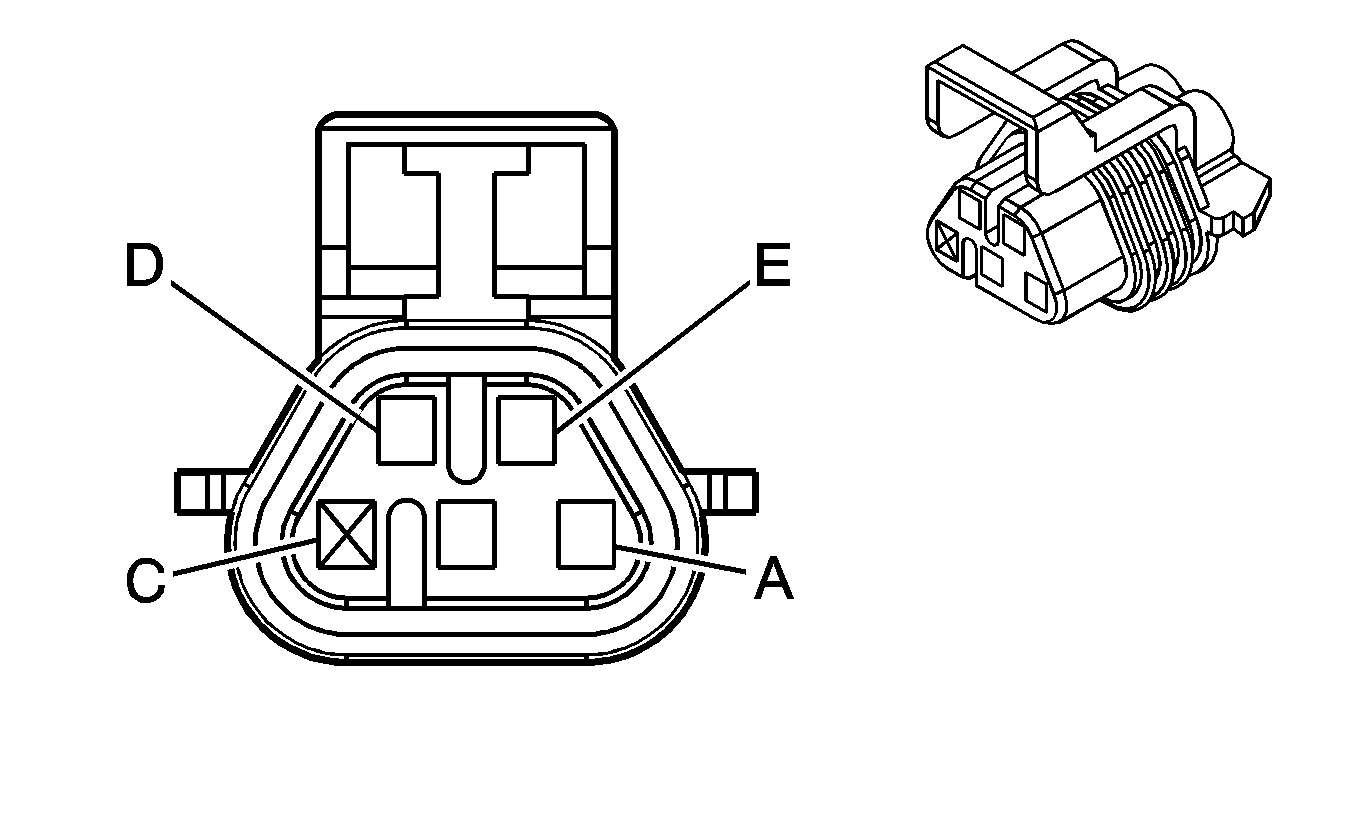
| Table 15: | High Idle Switch |
| Table 16: | Knock Sensor (RH) |
| Table 17: | Knock Sensor (LH) |
| Table 18: | Manifold Absolute Pressure (MAP) Sensor |
| Table 19: | Mass Air Flow (MAF) Sensor |
| Table 20: | Throttle Actuator |
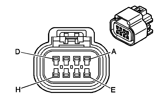
| Table 21: | Throttle Actuator Control Module-C1 |
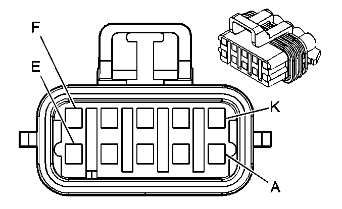
| Table 22: | Throttle Actuator Control (TAC) Module-C2 |
| Table 23: | Throttle Position (TP) Sensor |
| Table 24: | Transmission Speed Sensor |
| |||||||
|---|---|---|---|---|---|---|---|
Connector Part Information |
| ||||||
Pin | Wire Color | Circuit No. | Function | ||||
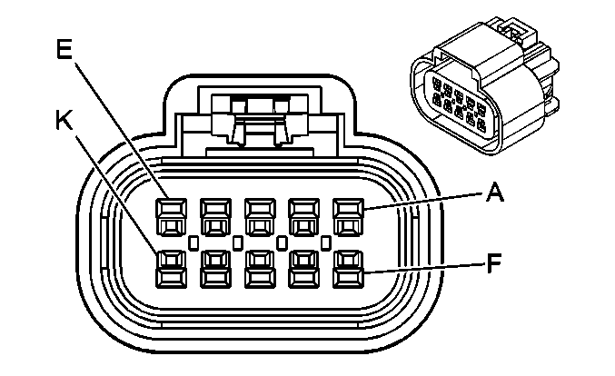
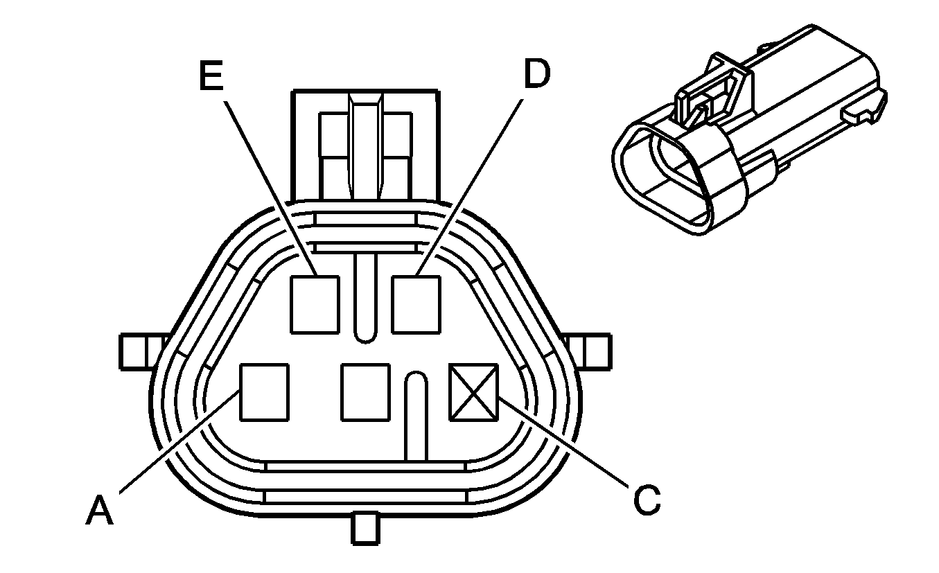
A | D-GN | 1163 | APP Sensor 3 Signal | ||||
B | YE/BK | 1275 | 5- Volt Reference | ||||
C | -- | -- | Not Used | ||||
D | WH/BK | 1164 | 5- Volt Reference | ||||
E | D-BU | 1161 | APP Sensor 1 Signal | ||||
F | GY | 1273 | Low Reference | ||||
G | PU | 1272 | Low Reference | ||||
H | L-BU | 1162 | APP Sensor 2 Signal | ||||
J | TN | 1274 | 5- Volt Reference | ||||
K | BN | 1271 | Low Reference | ||||
| |||||||
|---|---|---|---|---|---|---|---|
Connector Part Information |
| ||||||
Pin | Wire Color | Circuit No. | Function | ||||
A | RD | 631 | 12 Volt Reference | ||||
B | PK/BK | 632 | Low Reference | ||||
C | BN/WH | 633 | CMP Sensor Signal | ||||
| |||||||
|---|---|---|---|---|---|---|---|
Connector Part Information |
| ||||||
Pin | Wire Color | Circuit No. | Function | ||||
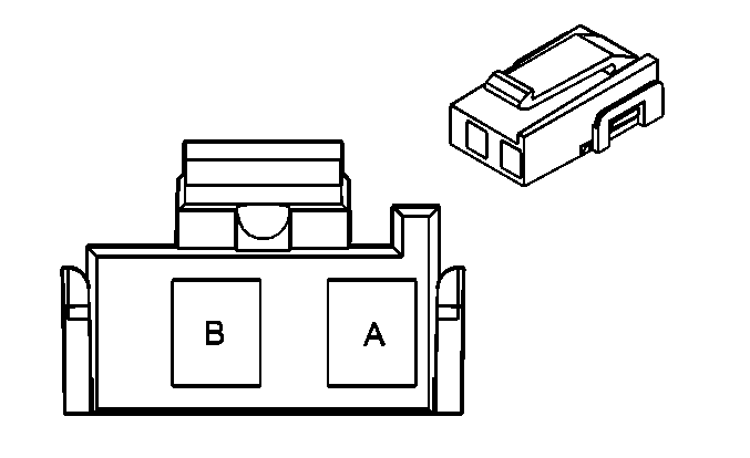
A | PK | 239 | Ignition 1 Voltage | ||||
B | D-GN/WH | 428 | EVAP Canister Purge Solenoid Control | ||||
| |||||||
|---|---|---|---|---|---|---|---|
Connector Part Information |
| ||||||
Pin | Wire Color | Circuit No. | Function | ||||
A | BN/WH | 379 | CPP Switch Signal | ||||
B | BN | 981 | Rear Floodlamp On Relay Control | ||||
| |||||||
|---|---|---|---|---|---|---|---|
Connector Part Information |
| ||||||
Pin | Wire Color | Circuit No. | Function | ||||
A | L-GN | 1478 | Coolant Level Switch Signal | ||||
B | BK/WH | 451 | Ground | ||||
| |||||||
|---|---|---|---|---|---|---|---|
Connector Part Information |
| ||||||
Pin | Wire Color | Circuit No. | Function | ||||
A | L-GN | 1867 | 12 Volt Reference | ||||
B | YE/BK | 1868 | Low Reference | ||||
C | D-BU/WH | 1869 | CKP Sensor Signal | ||||
| |||||||
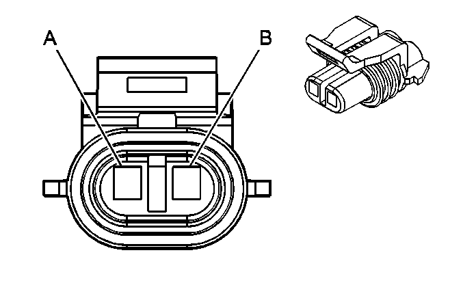
|---|---|---|---|---|---|---|---|
Connector Part Information |
| ||||||
Pin | Wire Color | Circuit No. | Function | ||||
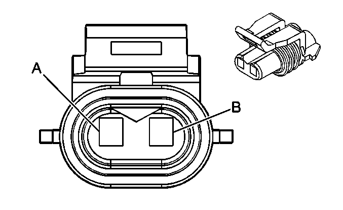
A | GY | 720 | Low Reference | ||||
B | YE | 410 | ECT Sensor Signal | ||||
| |||||||
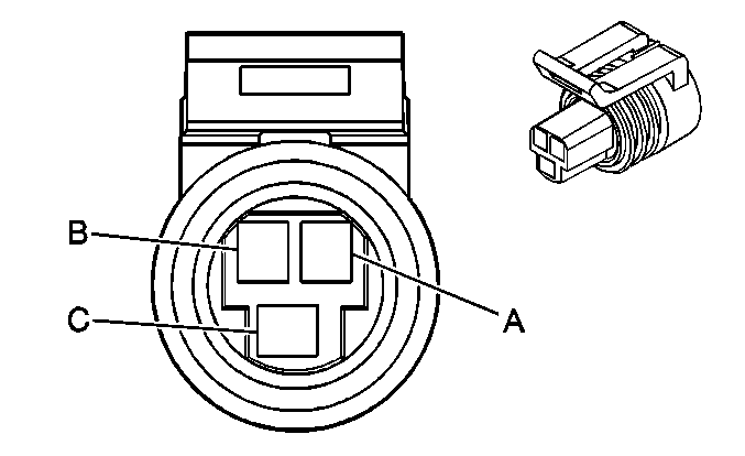
|---|---|---|---|---|---|---|---|
Connector Part Information |
| ||||||
Pin | Wire Color | Circuit No. | Function | ||||
A | BK | 407 | Low Reference | ||||
B | GY | 705 | 5 Volt Reference | ||||
C | TN/WH | 332 | Oil Pressure Sensor Signal | ||||
| |||||||
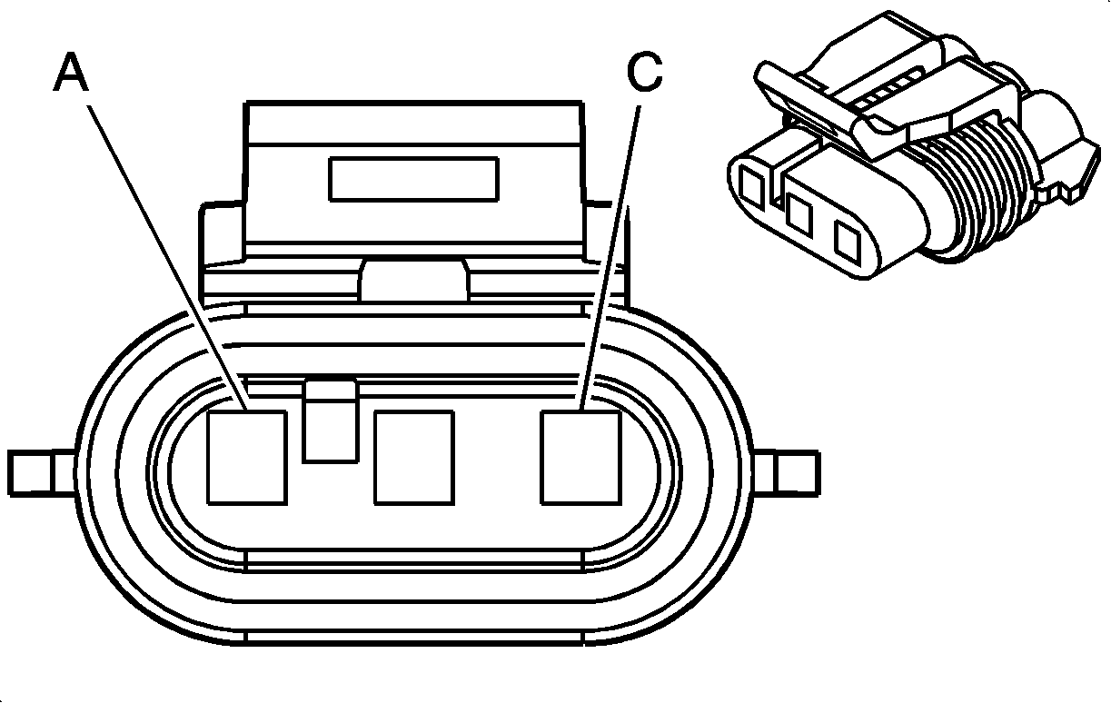
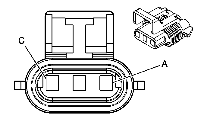
|---|---|---|---|---|---|---|---|
Connector Part Information |
| ||||||
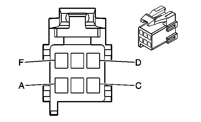
Pin | Wire Color | Circuit No. | Function | ||||
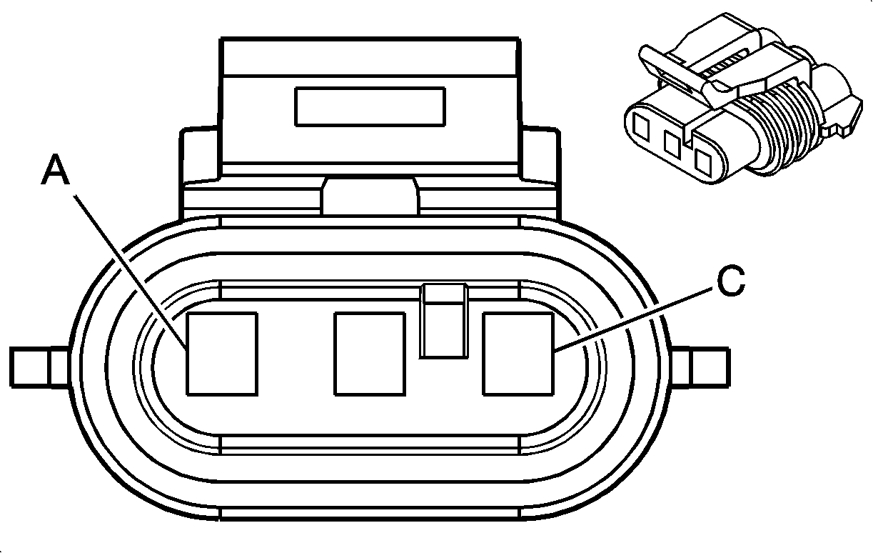
A | WH | 257 | EGR Solenoid High Control or EGR Solenoid Control | ||||
B | PU | 719 | Low Reference | ||||
C | BN | 1456 | EGR Valve Position Signal | ||||
D | GY | 596 | 5 Volt Reference | ||||
E | RD | 1676 | EGR Valve Supply Voltage | ||||
| |||||||
|---|---|---|---|---|---|---|---|
Connector Part Information |
| ||||||
Pin | Wire Color | Circuit No. | Function | ||||
30 | GY | 120 | Fuel Pump Supply Voltage | ||||
85 | TN | 1465 | Fuel Pump Relay Control-Secondary | ||||
86 | GY | 120 | Fuel Pump Supply Voltage | ||||
87 | L-GN | 1058 | Fuel Balance Pump Supply Voltage | ||||
|
| |||||||
|---|---|---|---|---|---|---|---|
Connector Part Information |
| ||||||
Pin | Wire Color | Circuit No. | Function | ||||
30 | GY | 120 | Fuel Pump Supply Voltage | ||||
85 | TN | 1465 | Fuel Pump Relay Control-Secondary | ||||
86 | GY | 120 | Fuel Pump Supply Voltage | ||||
87 | L-GN | 1058 | Fuel Balance Pump Supply Voltage | ||||
| |||||||
|---|---|---|---|---|---|---|---|
Connector Part Information |
| ||||||
Pin | Wire Color | Circuit No. | Function | ||||
1 | -- | -- | Not Used | ||||
2 | BK | 470 | Low Reference | ||||
3 | -- | -- | Not Used | ||||
4 | D-BU | 1936 | Fuel Level Sensor Signal - Secondary | ||||
| |||||||
|---|---|---|---|---|---|---|---|
Connector Part Information |
| ||||||
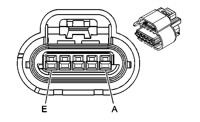
Pin | Wire Color | Circuit No. | Function | ||||
A | TN | 413 | HO2S Low Reference | ||||
B | PU/WH | 1665 | HO2S High Signal - Bank 1 Sensor 1 | ||||
D | L-GN/WH | 3213 | HO2S Heater High Control - Bank 2 Sensor 1 | ||||
E | L-GN | 3212 | HO2S Heater Low Control - Bank 2 Sensor 1 | ||||
| |||||||
|---|---|---|---|---|---|---|---|
Connector Part Information |
| ||||||
Pin | Wire Color | Circuit No. | Function | ||||
A | TN | 413 | HO2S Low Reference | ||||
B | PU | 1666 | HO2S High Signal - Bank 2 Sensor 1 | ||||
D | L-GN/WH | 3213 | HO2S Heater High Control - Bank 2 Sensor 1 | ||||
E | L-GN | 3212 | HO2S Heater Low Control - Bank 2 Sensor 1 | ||||
| |||||||
|---|---|---|---|---|---|---|---|
Connector Part Information |
| ||||||
Pin | Wire Color | Circuit No. | Function | ||||
A | BK | 750 | Ground | ||||
B | BK | 750 | Ground | ||||
C | D-GN | 534 | High Idle Switch Signal | ||||
D | BN | 985 | IA Heater Relay Control | ||||
E | BN | 2509 | Left Rear Park Lamps Supply Voltage/Left Rear Park Lamps | ||||
F | BK | 750 | Ground | ||||
| |||||||
|---|---|---|---|---|---|---|---|
Connector Part Information |
| ||||||
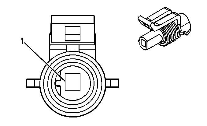
Pin | Wire Color | Circuit No. | Function | ||||
1 | L-BU | 1876 | Knock Sensor 2 Signal | ||||
|
| |||||||
|---|---|---|---|---|---|---|---|
Connector Part Information |
| ||||||
Pin | Wire Color | Circuit No. | Function | ||||
1 | D-BU | 496 | Knock Sensor 1 Signal | ||||
|
| |||||||
|---|---|---|---|---|---|---|---|
Connector Part Information |
| ||||||
Pin | Wire Color | Circuit No. | Function | ||||
A | OG/BK | 469 | Low Reference | ||||
B | L-GN | 432 | MAP Sensor Signal | ||||
C | GY | 597 | 5 Volt Reference | ||||
| |||||||
|---|---|---|---|---|---|---|---|
Connector Part Information |
| ||||||
Pin | Wire Color | Circuit No. | Function | ||||
A | BK | 552 | Low Reference | ||||
B | TN | 472 | IAT Sensor Signal | ||||
C | BK/WH | 351 | Ground | ||||
D | PK | 239 | Ignition 1 Voltage | ||||
E | YE | 492 | MAF Sensor Signal | ||||
| |||||||
|---|---|---|---|---|---|---|---|
Connector Part Information |
| ||||||
Pin | Wire Color | Circuit No. | Function | ||||
A | BN | 582 | TAC Motor Control - 2 | ||||
B | YE | 581 | TAC Motor Control - 1 | ||||
| |||||||
|---|---|---|---|---|---|---|---|
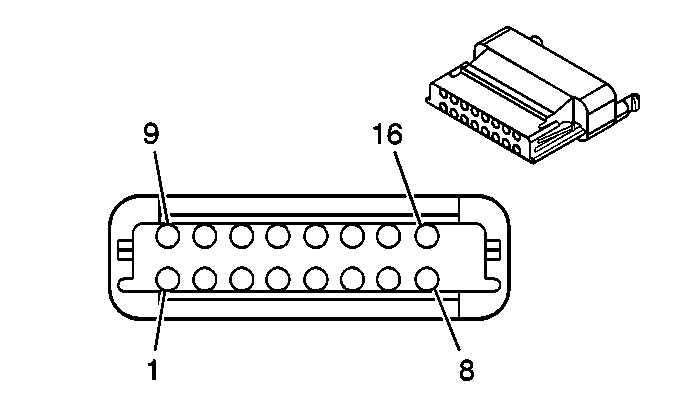
Connector Part Information |
| ||||||
Pin | Wire Color | Circuit No. | Function | ||||
1 | D-GN | 485 | TP Sensor 1 Signal | ||||
2 | GY | 416 | 5 Volt Reference | ||||
3 | BK | 452 | Low Reference | ||||
4 | D-BU | 84 | Cruise Control Set/Coast Switch Signal | ||||
5 | GY/BK | 87 | Control Switch Signal | ||||
6 | L-BU | 1320 | CHMSL Supply Voltage/Stop Lamp Supply Voltage | ||||
7 | PK | 439 | Ignition 1 Voltage | ||||
8 | BN | 582 | TAC Motor Control - 2 | ||||
9 | L-BU/BK | 1688 | 5 Volt Reference | ||||
10 | BK/WH | 1704 | Low Reference | ||||
11 | PU | 486 | TP Sensor 2 Signal | ||||
12 | OG/BK | 1061 | UART Serial Data Secondary | ||||
13 | D-BU/WH | 774 | UART Serial Data Tertiary | ||||
14 | GY | 397 | Cruise Control On Switch Signal | ||||
15 | BK/WH | 351 | Ground | ||||
16 | YE | 581 | TAC Motor Control - 1 | ||||
| |||||||
|---|---|---|---|---|---|---|---|
Connector Part Information |
| ||||||
Pin | Wire Color | Circuit No. | Function | ||||
A | BN | 1271 | Low Reference | ||||
B | PU | 1272 | Low Reference | ||||
C | L-BU | 1162 | APP Sensor 2 Signal | ||||
D | TN | 1274 | 5 Volt Reference | ||||
E | YE/BK | 1275 | 5 Volt Reference | ||||
F | D-BU | 1161 | APP Sensor 1 Signal | ||||
G | WH/BK | 1164 | 5 Volt Reference | ||||
H | -- | -- | Not Used | ||||
J | GY | 1273 | Low Reference | ||||
K | D-GN | 1163 | APP Sensor 3 Signal | ||||
| |||||||
|---|---|---|---|---|---|---|---|
Connector Part Information |
| ||||||
Pin | Wire Color | Circuit No. | Function | ||||
A | GY | 416 | 5 Volt Reference | ||||
B | BK | 452 | Low Reference | ||||
C | D-GN | 485 | TPP Sensor 1 Signal | ||||
D | L-BU/BK | 1688 | 5 Volt Reference | ||||
E | BK/WH | 1704 | Low Reference | ||||
F | PU | 488 | APP Sensor 1 Signal | ||||
G | GY | 1273 | Low Reference | ||||
H | D-GN | 1163 | APP Sensor 3 Signal | ||||
| |||||||
|---|---|---|---|---|---|---|---|
Connector Part Information |
| ||||||
Pin | Wire Color | Circuit No. | Function | ||||
1 | L-BU | 2221 | Signal High - Rear | ||||
2 | D-GN | 2222 | Signal Low - Rear | ||||
