Removal Procedure
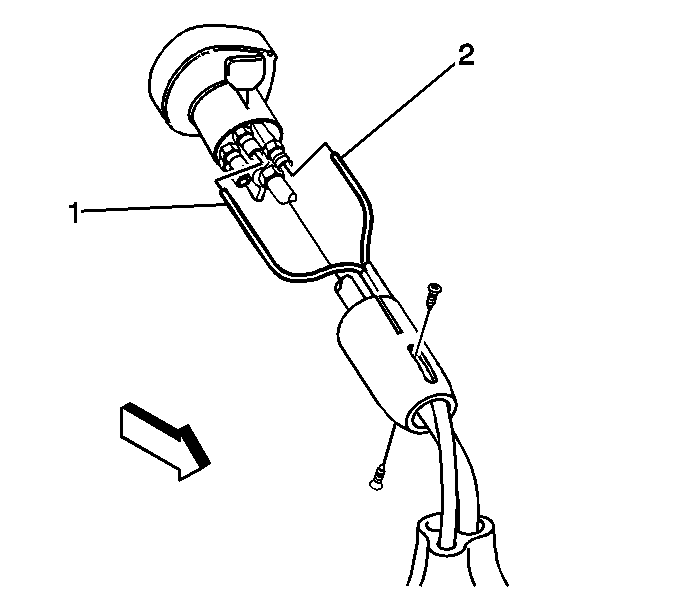
- Exhaust all air pressure from the system, if equipped.
- If equipped, with a Eaton® Fuller® 9 or 10 speed transmission, remove the screws from the control lever shift sheath.
- Slide the sheath down the shift lever.
- If equipped with the 9 speed transmission, disconnect the following tubes:
| • | Red tube (1) from the "S" port |
| • | Black tube (2) from the "P" port |
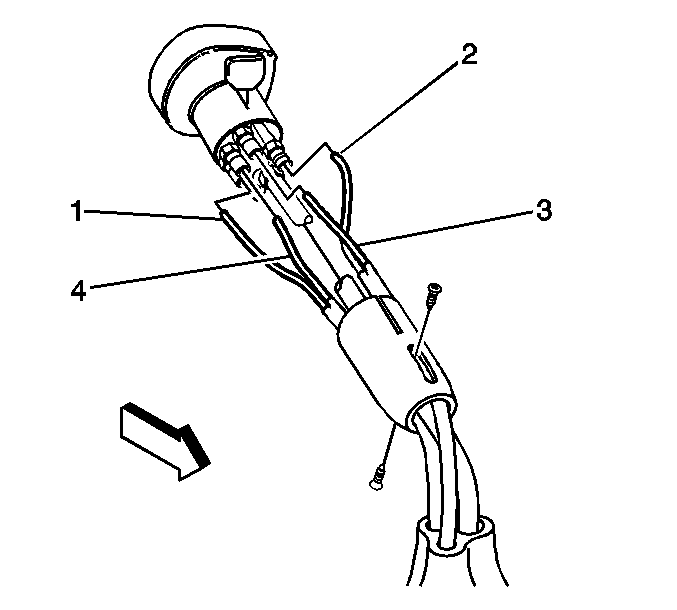
- If equipped with the 10 speed transmission, disconnect the following
tubes:
| • | Blue tube (1) from the "SP" port |
| • | Black tube (2) from the "P" port |
| • | Red tube (3) from the "S" port |
| • | Green tube (4) from the "H" port to "L" port |
- Cap the tube openings.
- Perform the following steps in order to remove the air shift control lever:
| 7.1. | Loosen the lock nut. |
| 7.2. | Unscrew the shift control lever. |
| 7.3. | Slide off the sheath, if necessary. |
- If equipped, with the Eaton® Fuller® 9 or 10 speed transmission, remove the control lever .
- Remove the control lever boot pin.
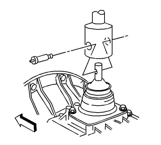
- Remove the control lever.
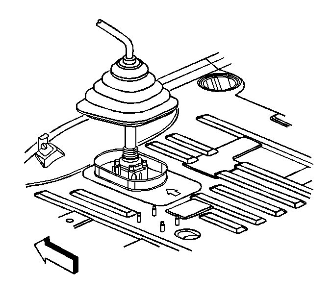
- If equipped with a Spicer® transmission, RPOs MK8/MK9, remove the control lever boot retainer bolt.
- Remove the control lever boot.
- Lift up the control lever boot.
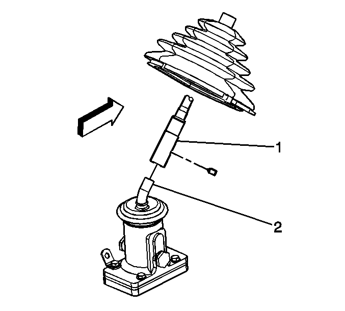
- If equipped with a Spicer® transmission, RPOs MK8/MK9, loosen the set screw (1).
- Remove the control lever and boot.
Installation Procedure

- If equipped with a Spicer® transmission, RPOs MK8/MK9, install the control lever and boot.
Notice: Refer to Fastener Notice in the Preface section.
- Tighten the control lever set screw (1).
Tighten
Tighten the control lever set screw to 39 N·m (28 lb ft).
- Push down the control lever boot.

- Install the control lever.
- Install the retaining pin.

- If equipped, with the Eaton® Fuller® 9 or 10 speed transmission, install the control lever boot .

- Perform the following steps in order to install the air shift control lever:
| 7.1. | Slide on the sheath, if necessary. |
| 7.2. | Screw on the shift control lever. |
| 7.3. | Tighten the lock nut. |
Tighten
Tighten the shift lever lock nut to 25 N·m (18 lb ft).
- Remove the caps from the tube openings.
- If equipped with the 10 speed transmission, connect the following tubes:
| • | Blue tube (1) to the "SP" port |
| • | Black tube (2) to the "P" port |
| • | Red tube (3) to the "S" port |
| • | Green tube (4) to the "H" port to "L" port |

- If equipped with the 9 speed transmission, connect the following tubes:
| • | Red tube (1) to the "S" port |
| • | Black tube (2) to the "P" port |
- Slide the sheath up the shift lever.
- If equipped, with a Eaton® Fuller® 9 or 10 speed transmission, install the screws to the control lever shift sheath.
Tighten
Tighten the control lever shift sheath screws to 5 N·m (44 lb in).
- Pressurize the air system, if equipped.
- Operate the shift control lever to check for leaks, if equipped.


