For 1990-2009 cars only
Tools Required
| • | J 46003 Output Shaft Bearing Locknut Wrench |
| • | J 46001 Differential Drive Pinion Holding Tool |
Disassembly
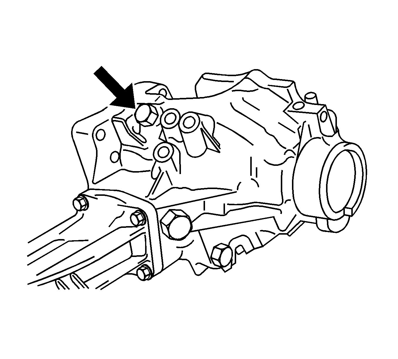
- Remove the No.1 plug from the transfer case assembly.
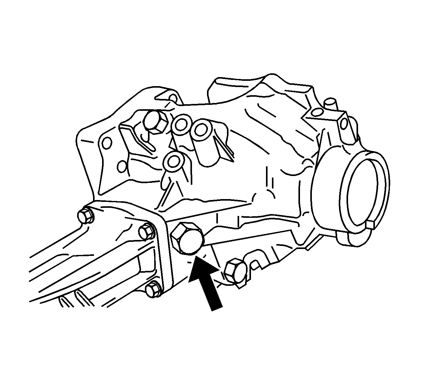
- Remove the No.2 plug from the transfer case assembly.
- Place a drain pan under the transfer case.
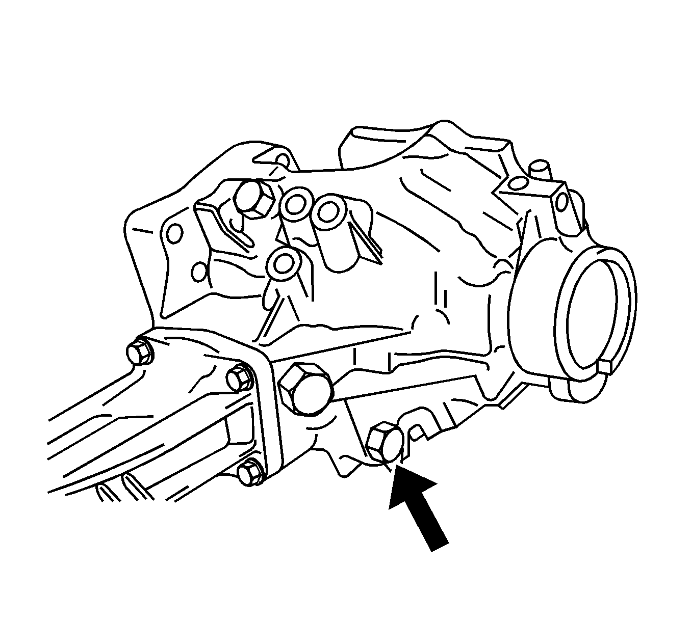
- Remove the drain plug from the transfer case assembly.
- Remove the breather plug from the transfer case assembly.
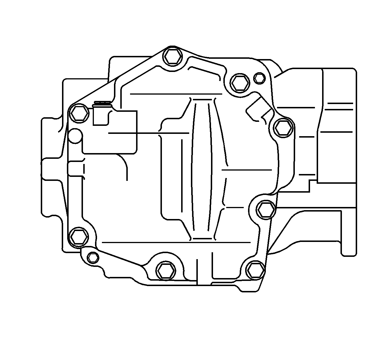
- Remove the transfer case cover bolts.
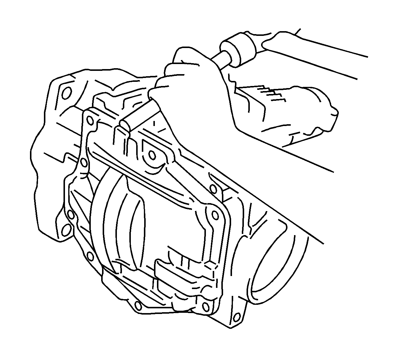
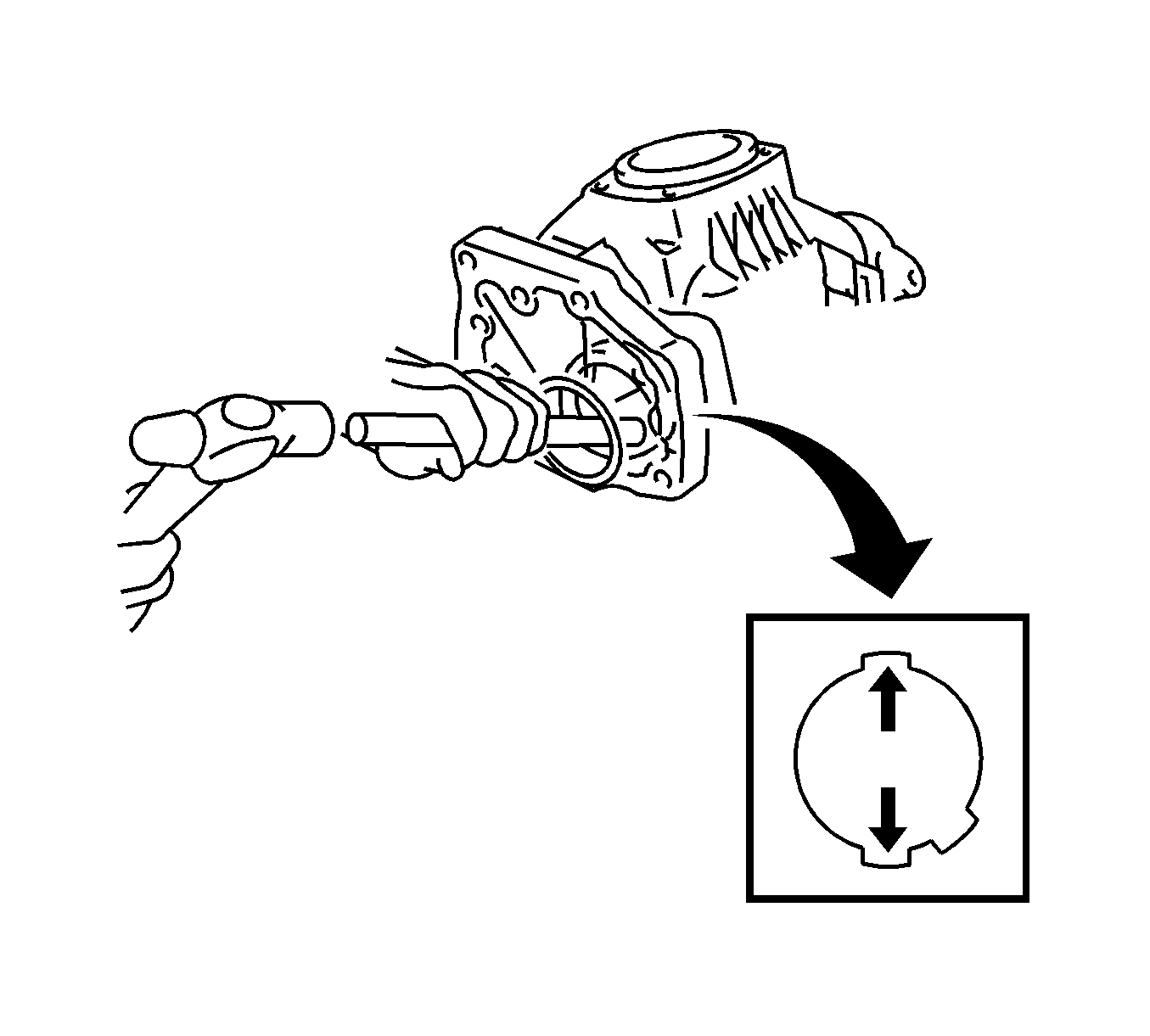
- Using a brass drift and a hammer, remove the transfer case cover from the case.
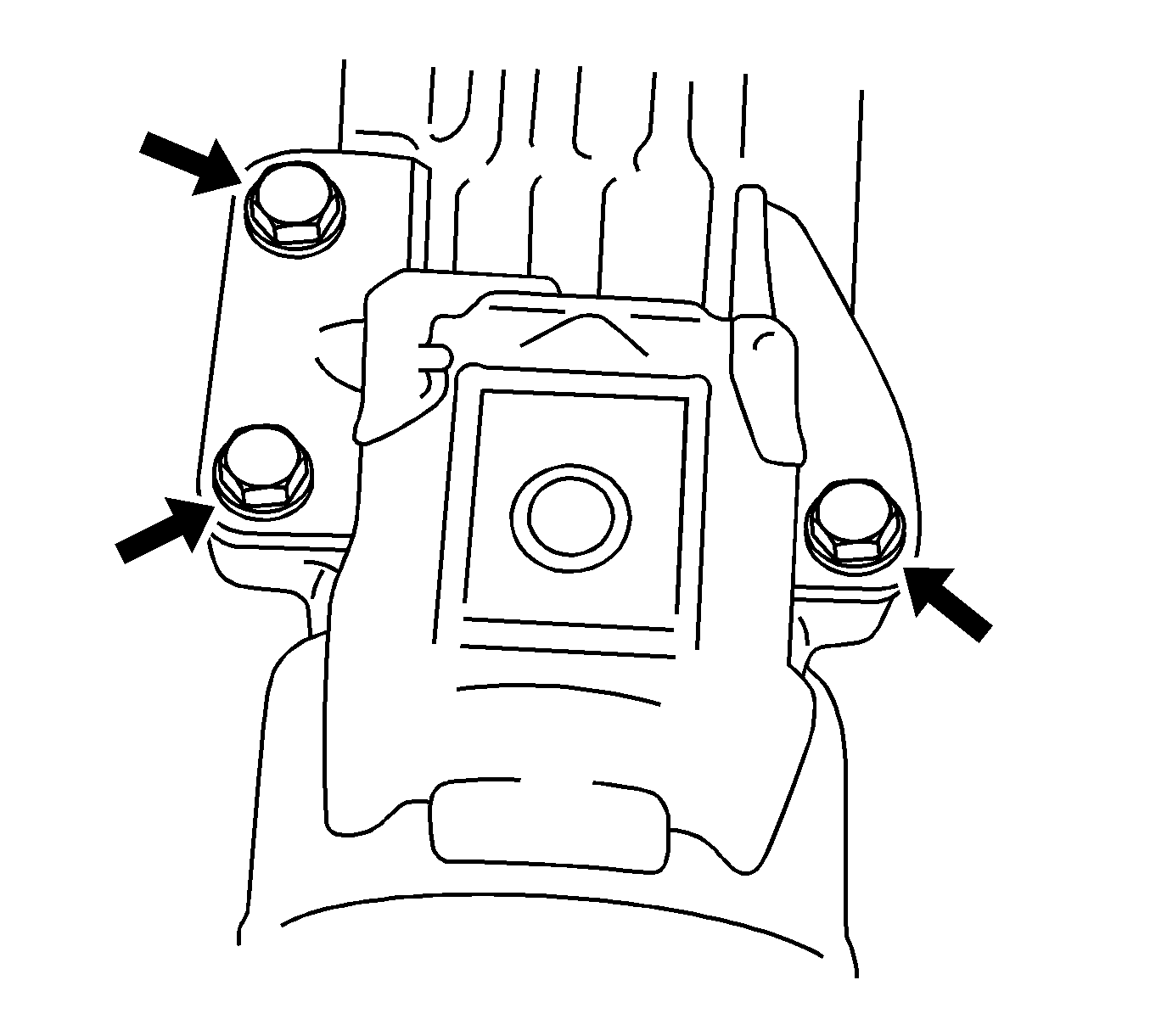
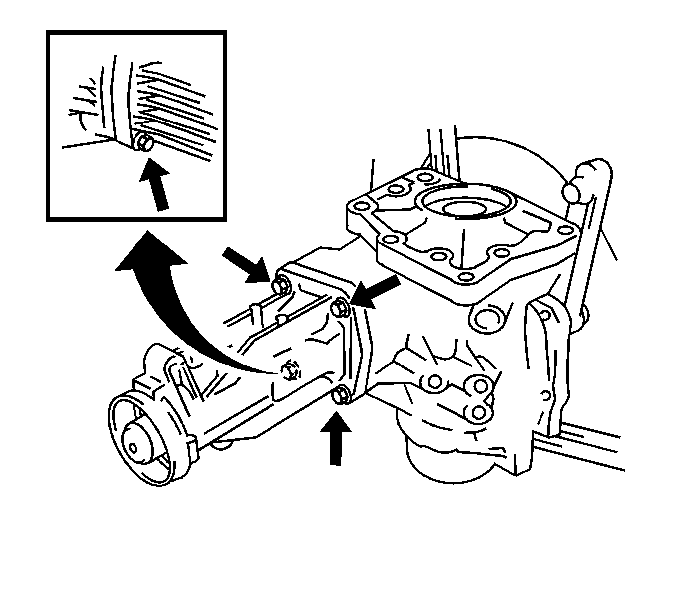
- Remove the 3 transfer case mount bolts.
- Remove the mount from the extension housing.
- Remove the 4 alignment pins from the transfer case.
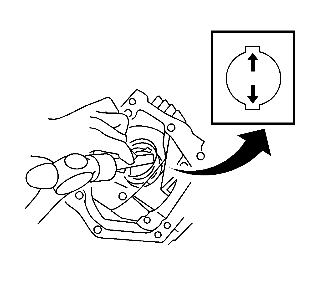
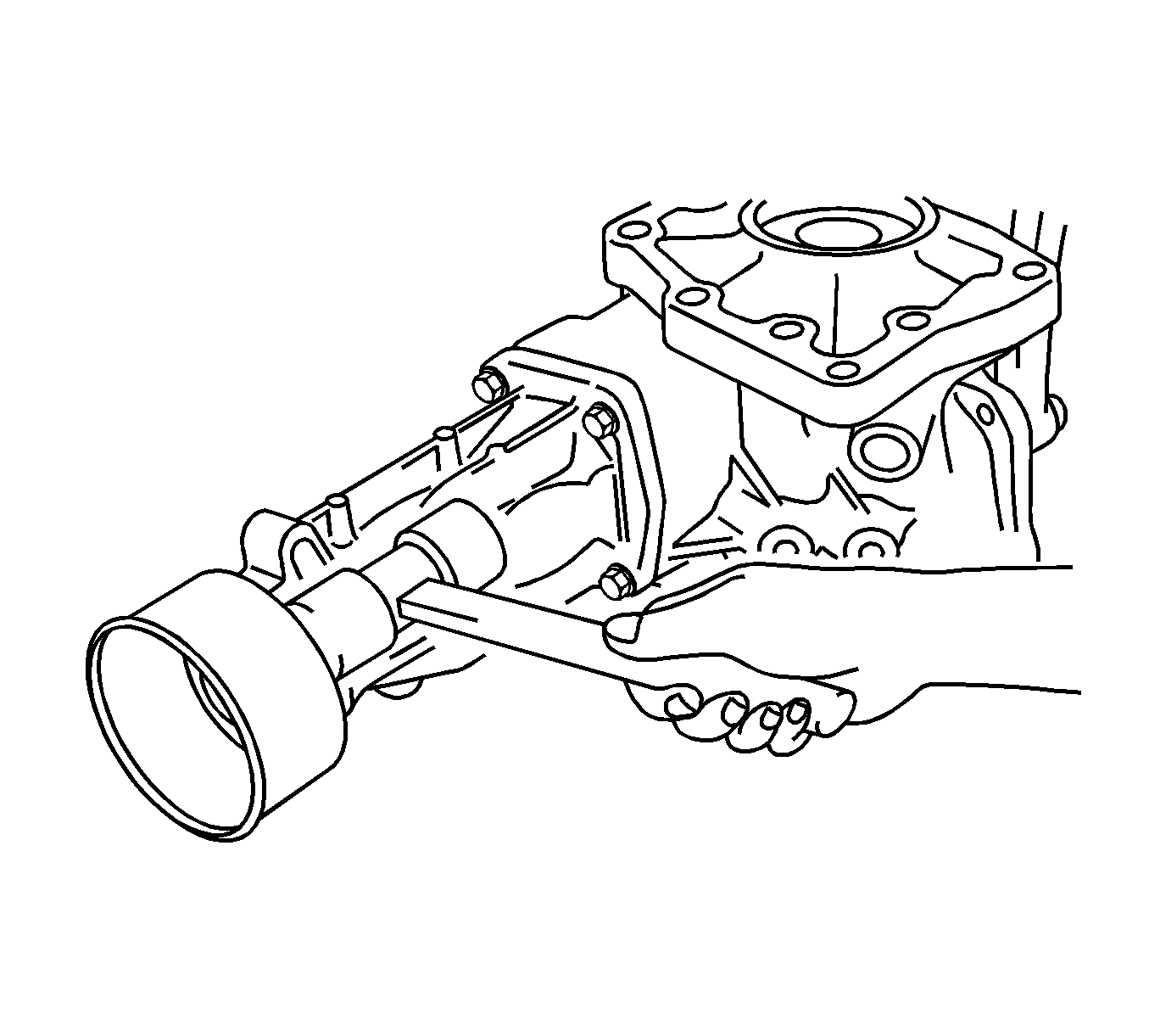
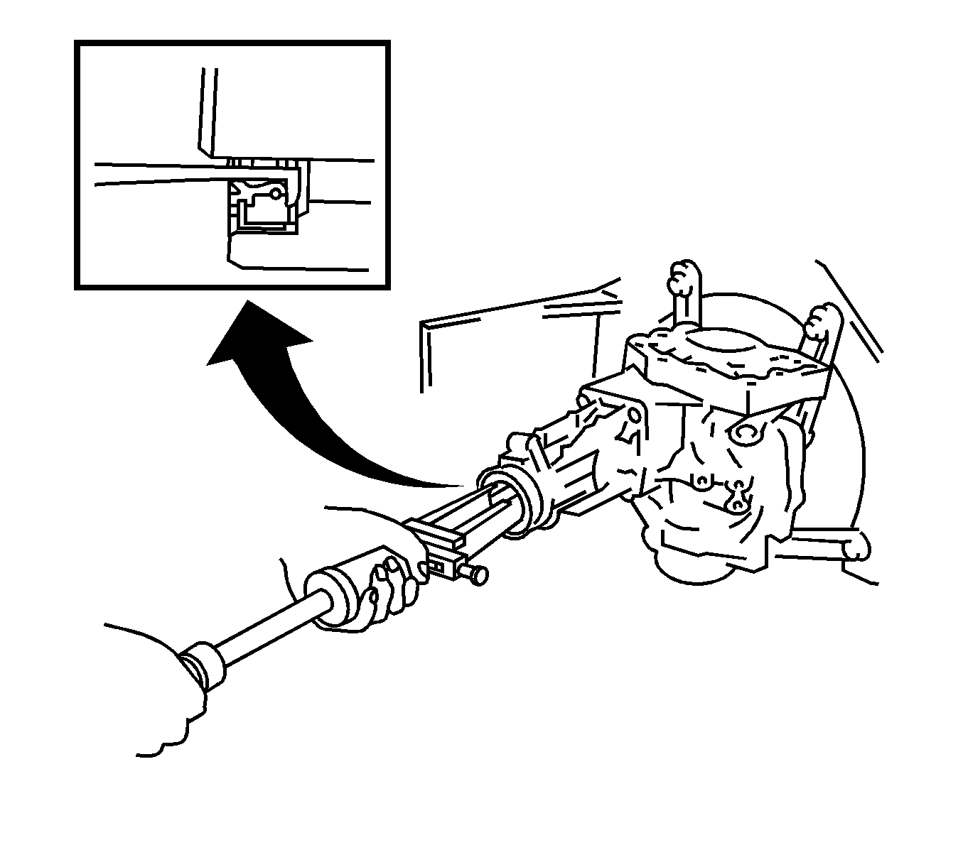
- Using a soft faced hammer, remove the extension housing dust deflector.
- Remove the oil seal from the extension housing.
- Remove the 4 extension housing retaining bolts.
- Remove the extension housing from the transfer case.
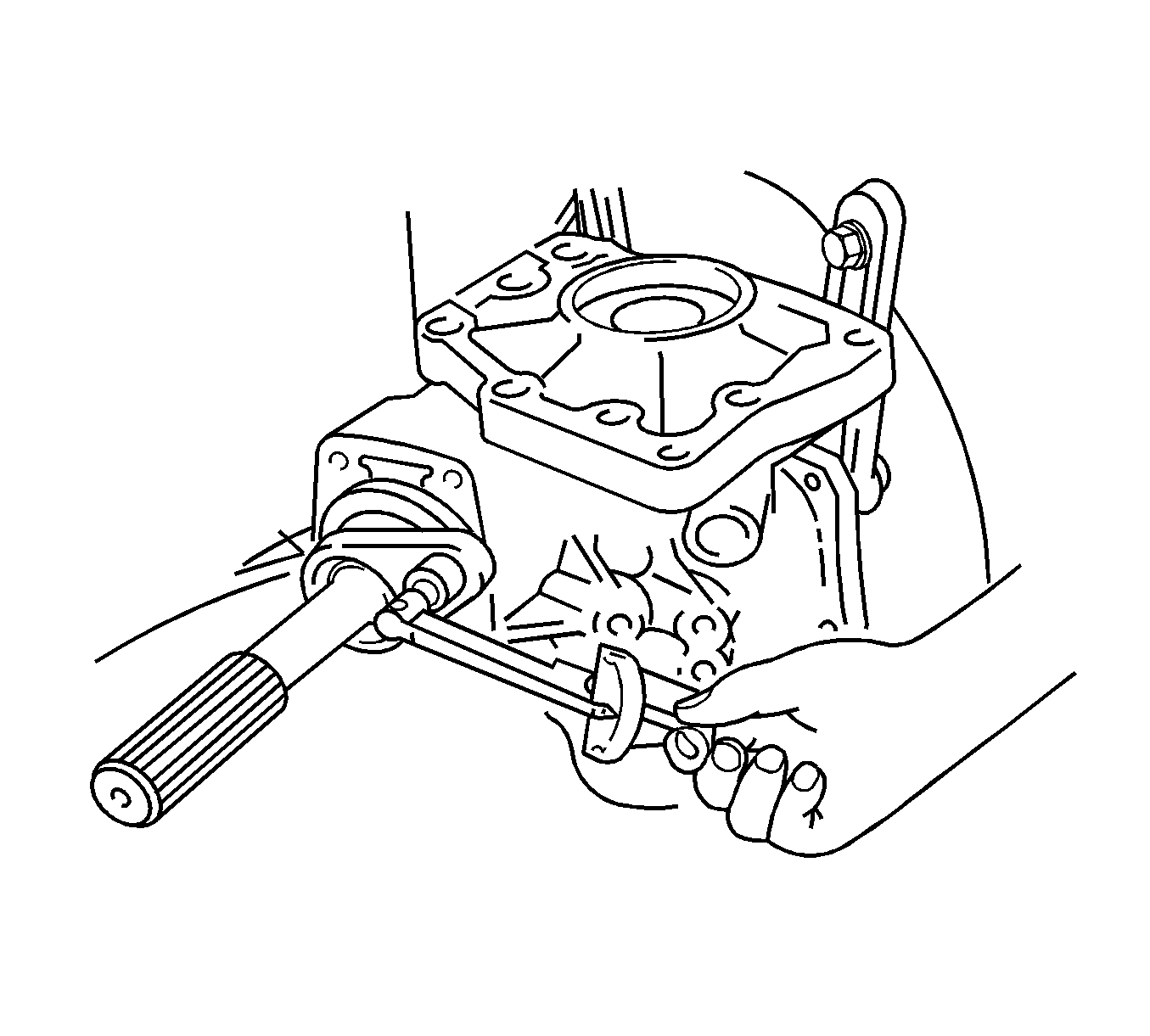
- Using J 46003 and a torque wrench, measure the preload of the backlash between the drive pinion and the ring gear.
- Using a dial indicator, check the backlash of the ring gear.
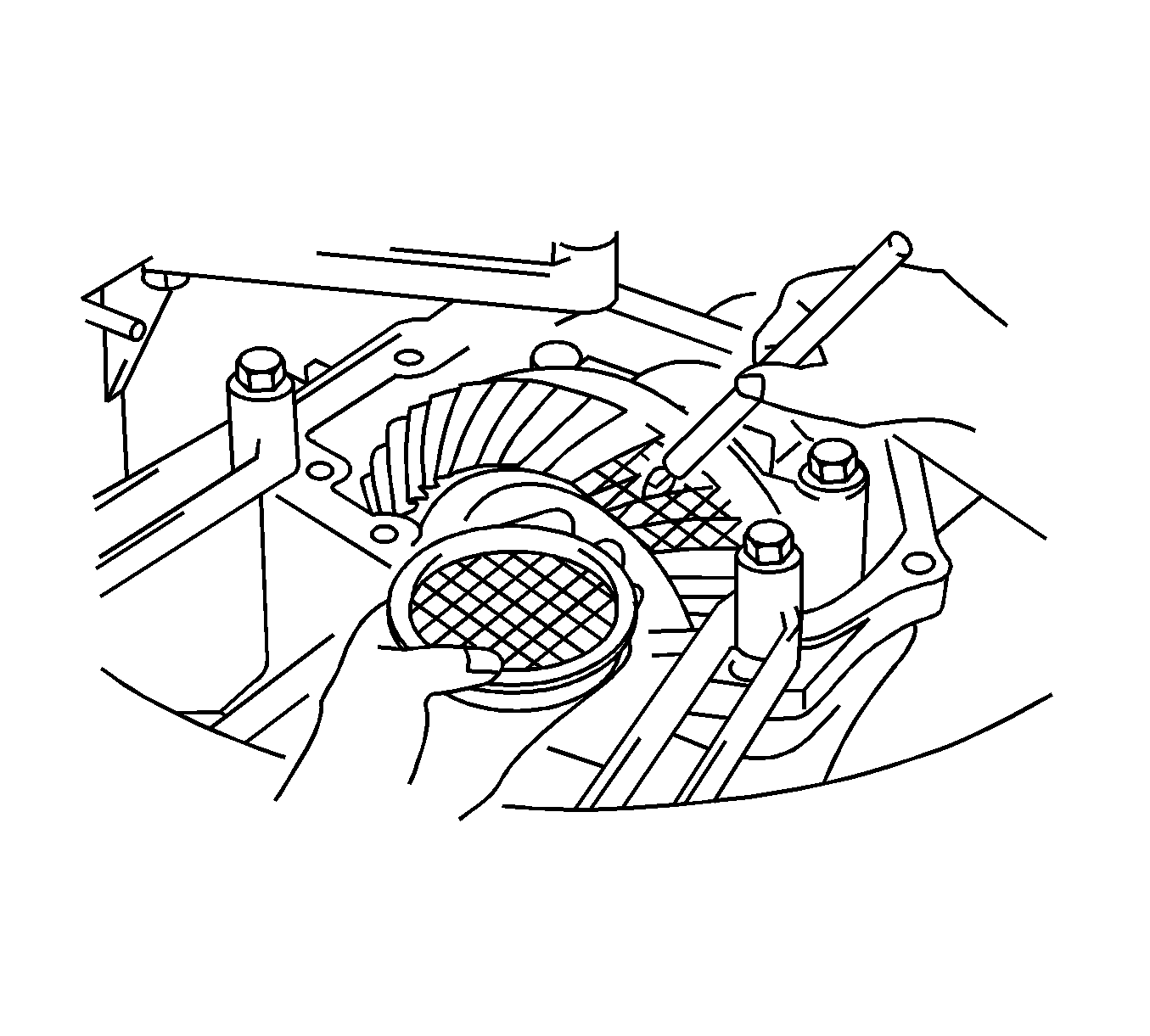
- Coat the teeth of the ring gear with Gear Marking Compound GM P/N 1052351 (Canadian P/N 10953497).
- Rotate the ring gear.
- Inspect the ring gear contact pattern.
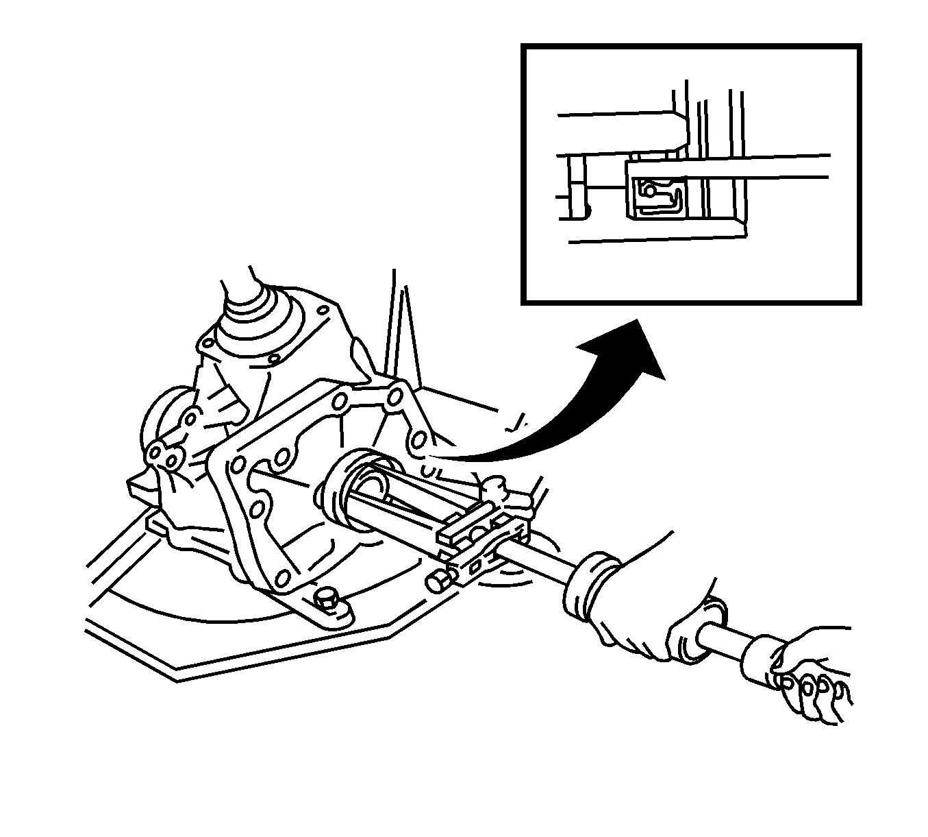
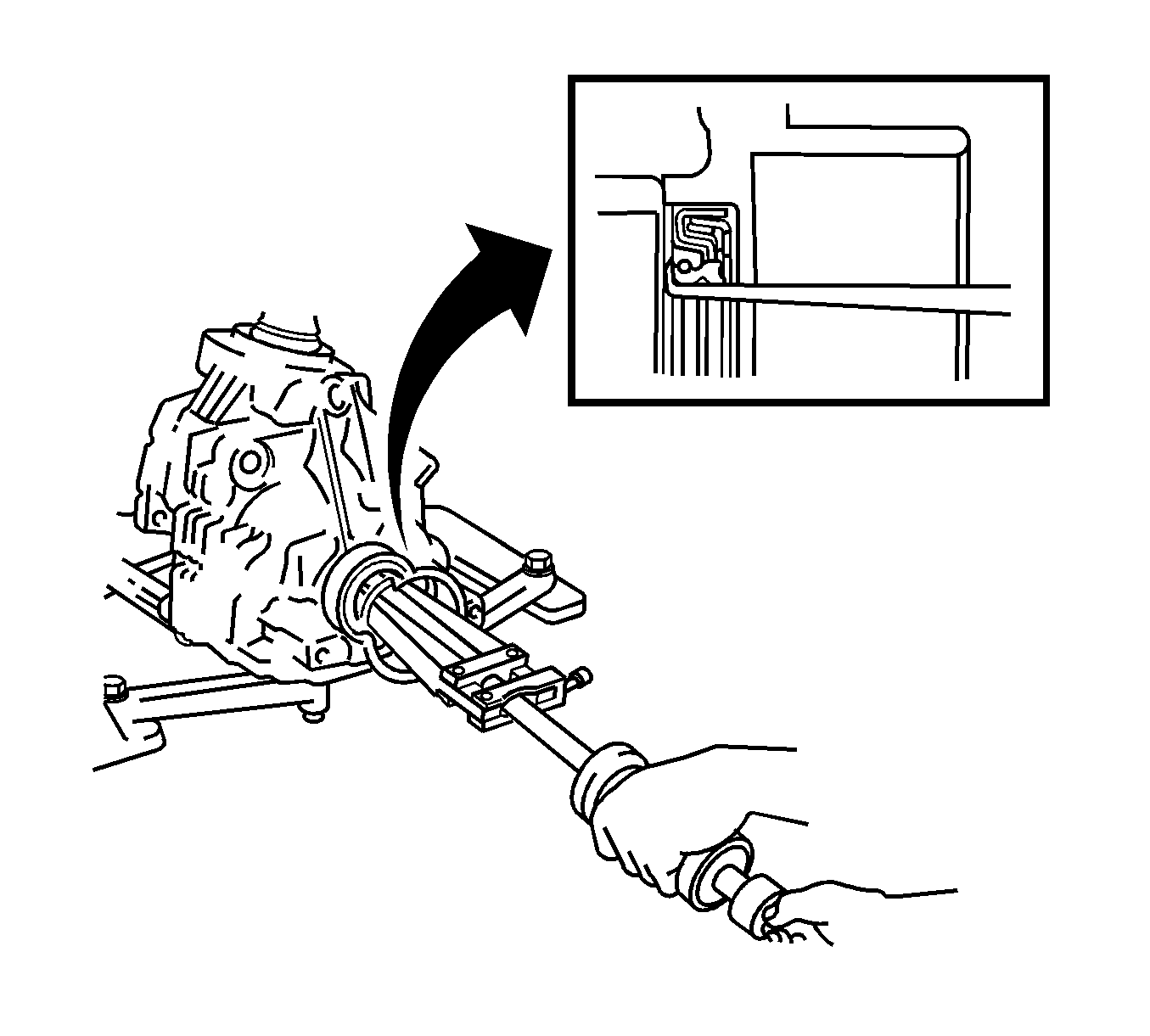
- Remove the left transfer case oil seal.
- Remove the right transfer case oil seal.
- Remove the bearing cap bolts and bearing cap from the ring gear assembly.
- Remove the output shaft spacer from the ring gear mounting case.
- Remove the ring gear mounting case washer.
- Remove the ring gear mounting case from the transfer case.
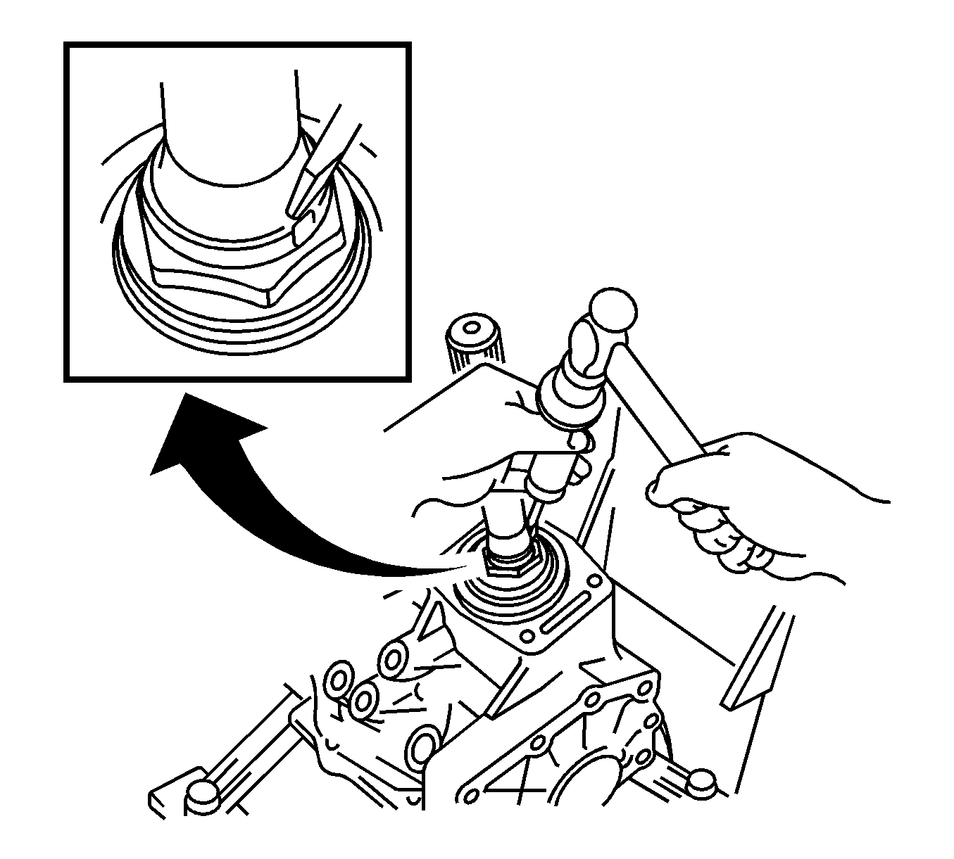
- Using a punch and a hammer, unstake the drive pinion nut.
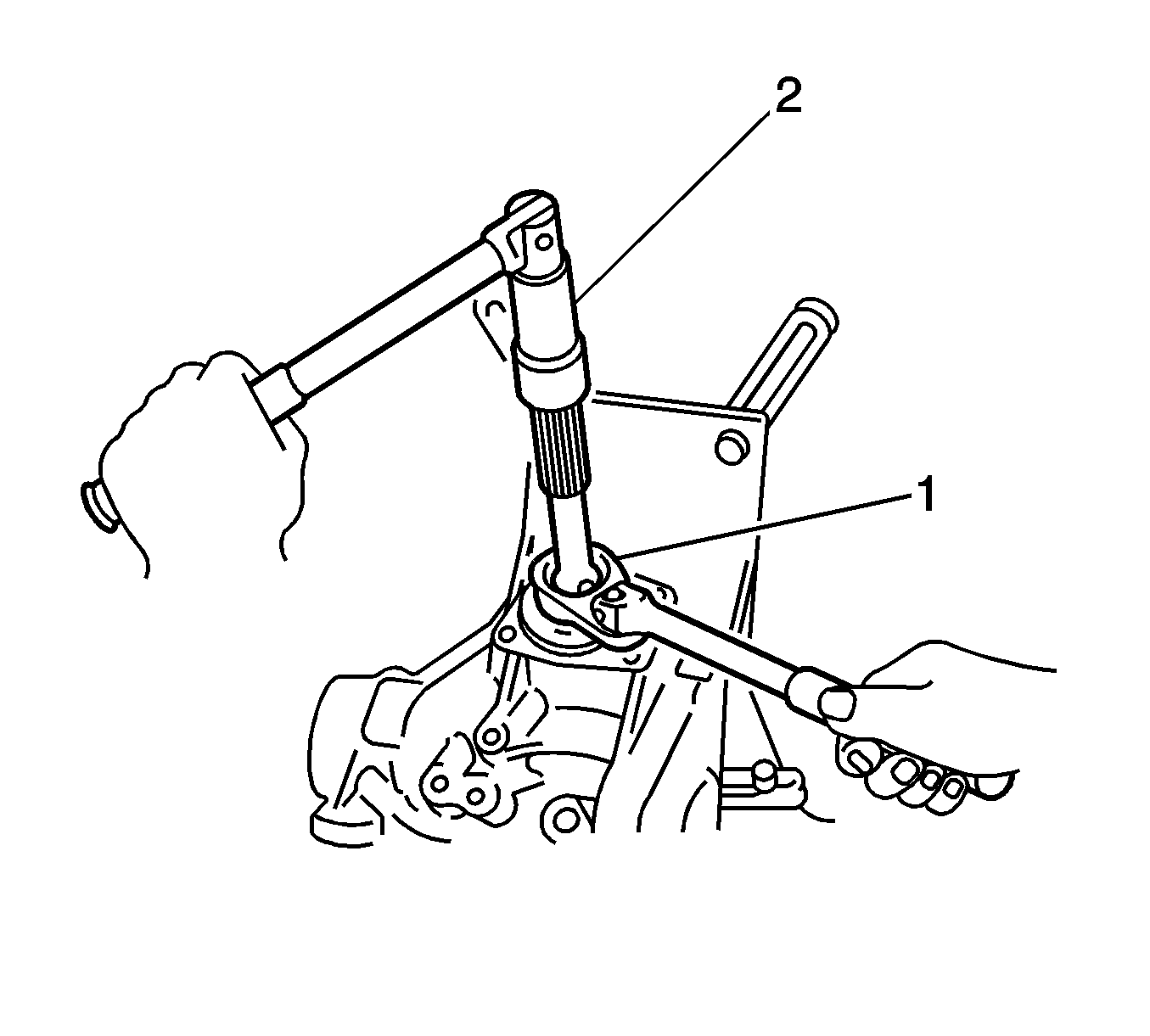
- Using J 46003 and J 46001 remove the drive pinion retaining nut.
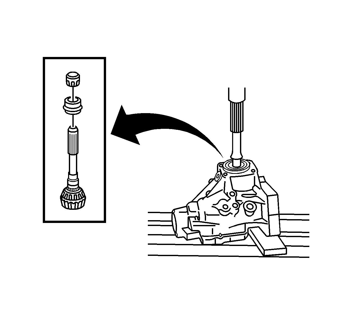
- Using a press, remove the drive pinion, spacer and washer from the transfer case.
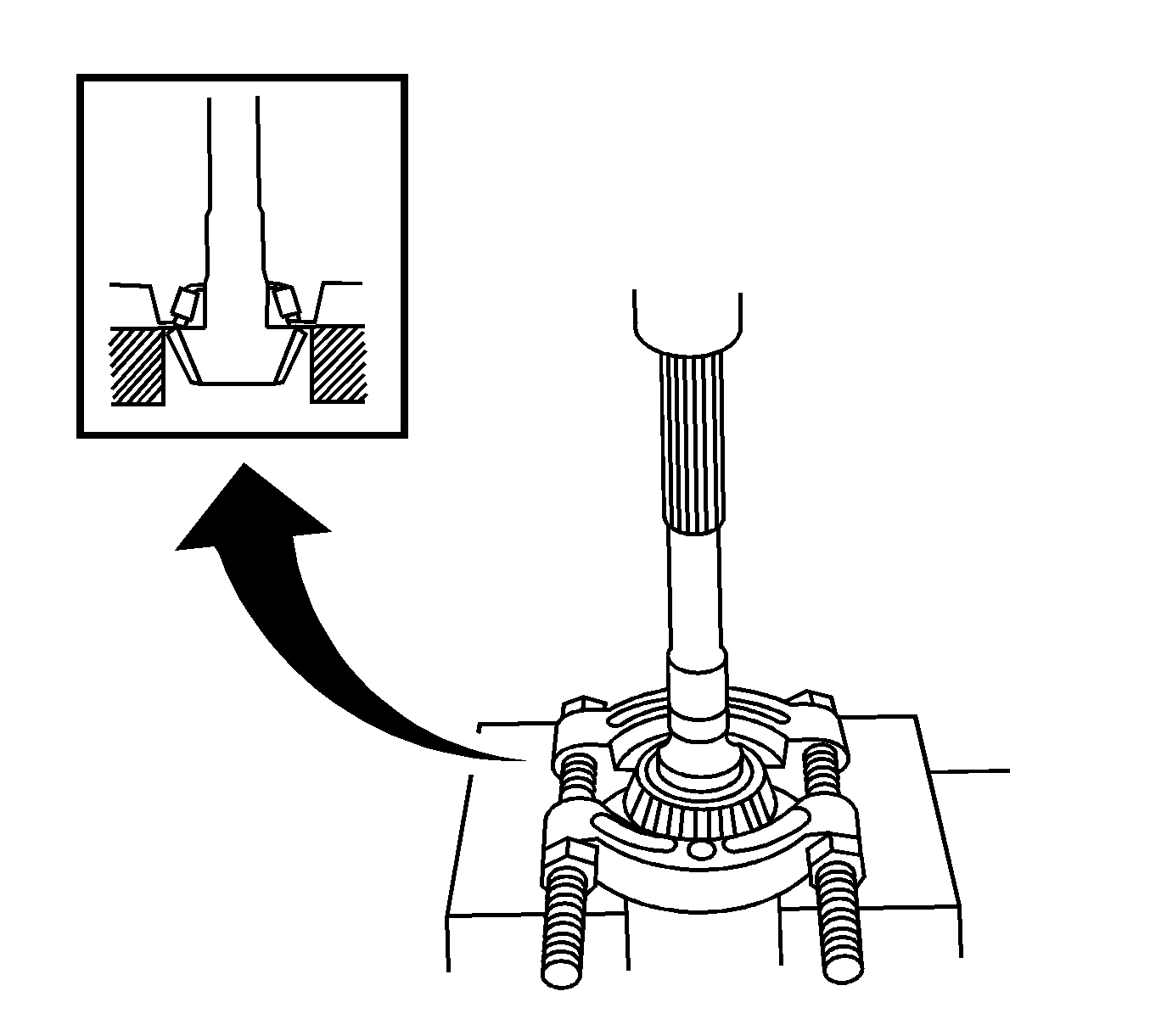
- Using a press, remove the drive pinion bearing from the drive pinion.
- Using a brass bar and a hammer, remove the drive pinion bearing race from the transfer case.
- Using a press, remove the left and right ring gear mounting case bearings.
- Using a brass bar and hammer, remove the left outer race from the transfer case.
- Using a brass bar and hammer, remove the right outer race from the transfer case.
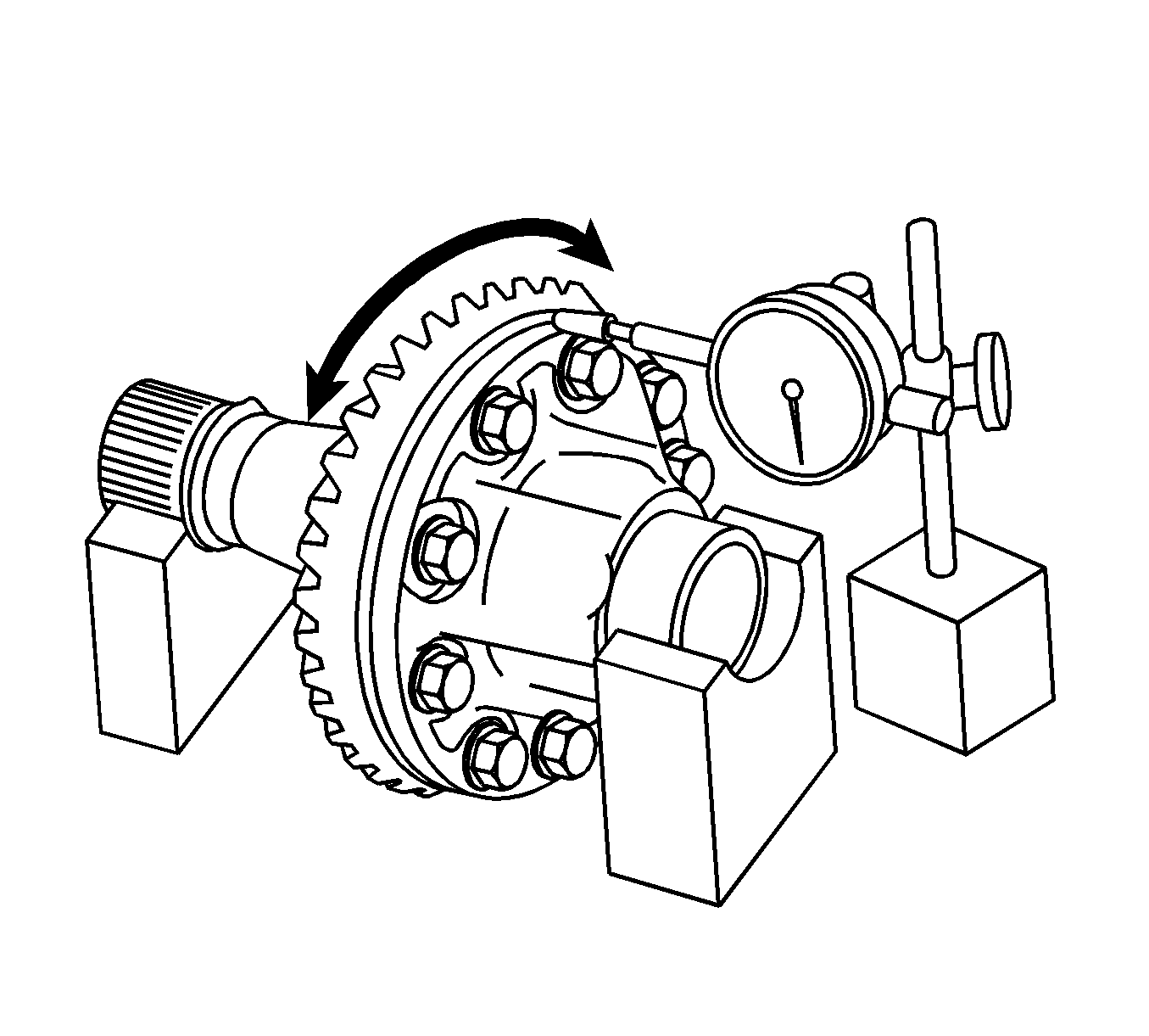
- Using a dial indicator, check the runout of the ring gear.
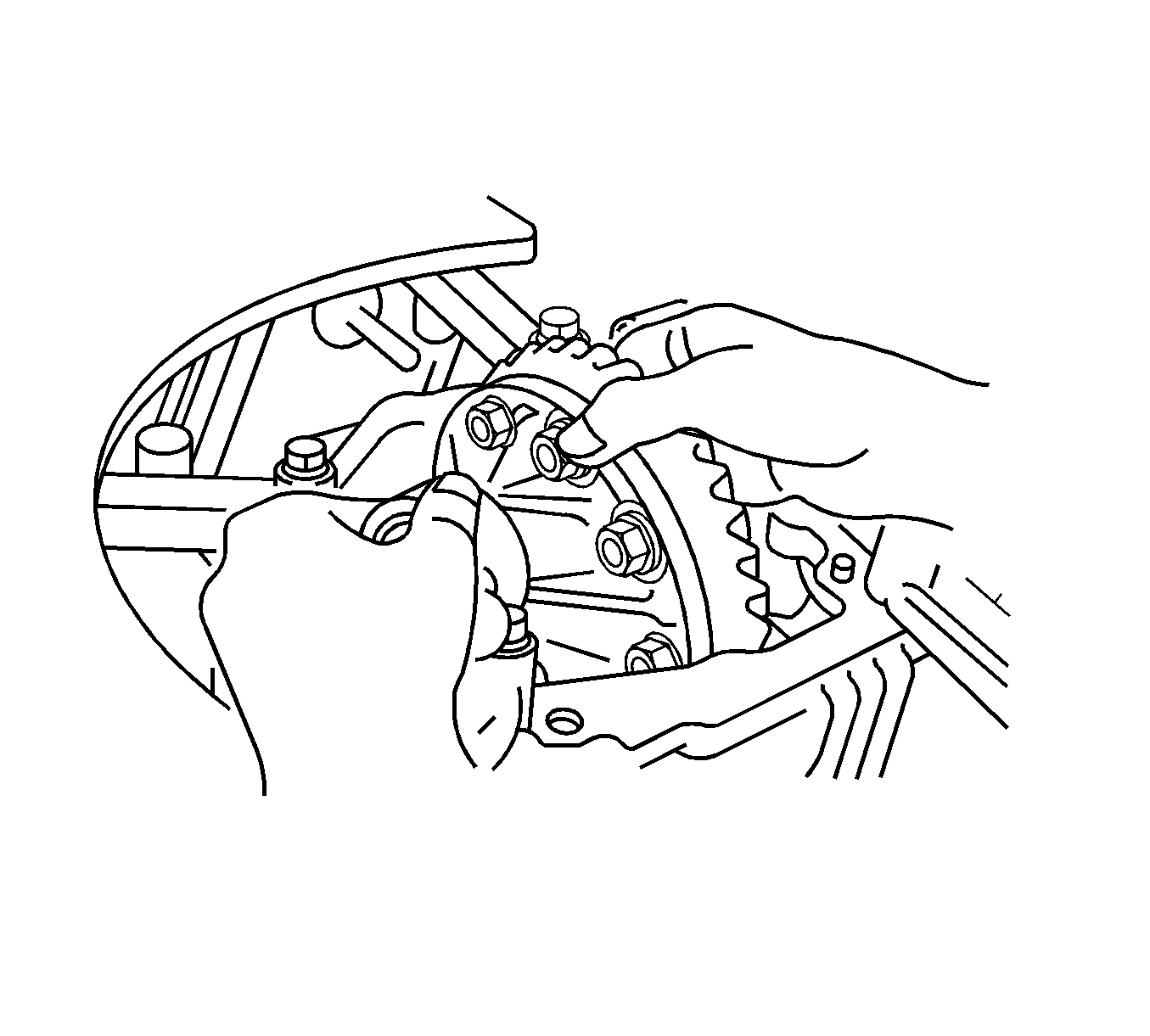
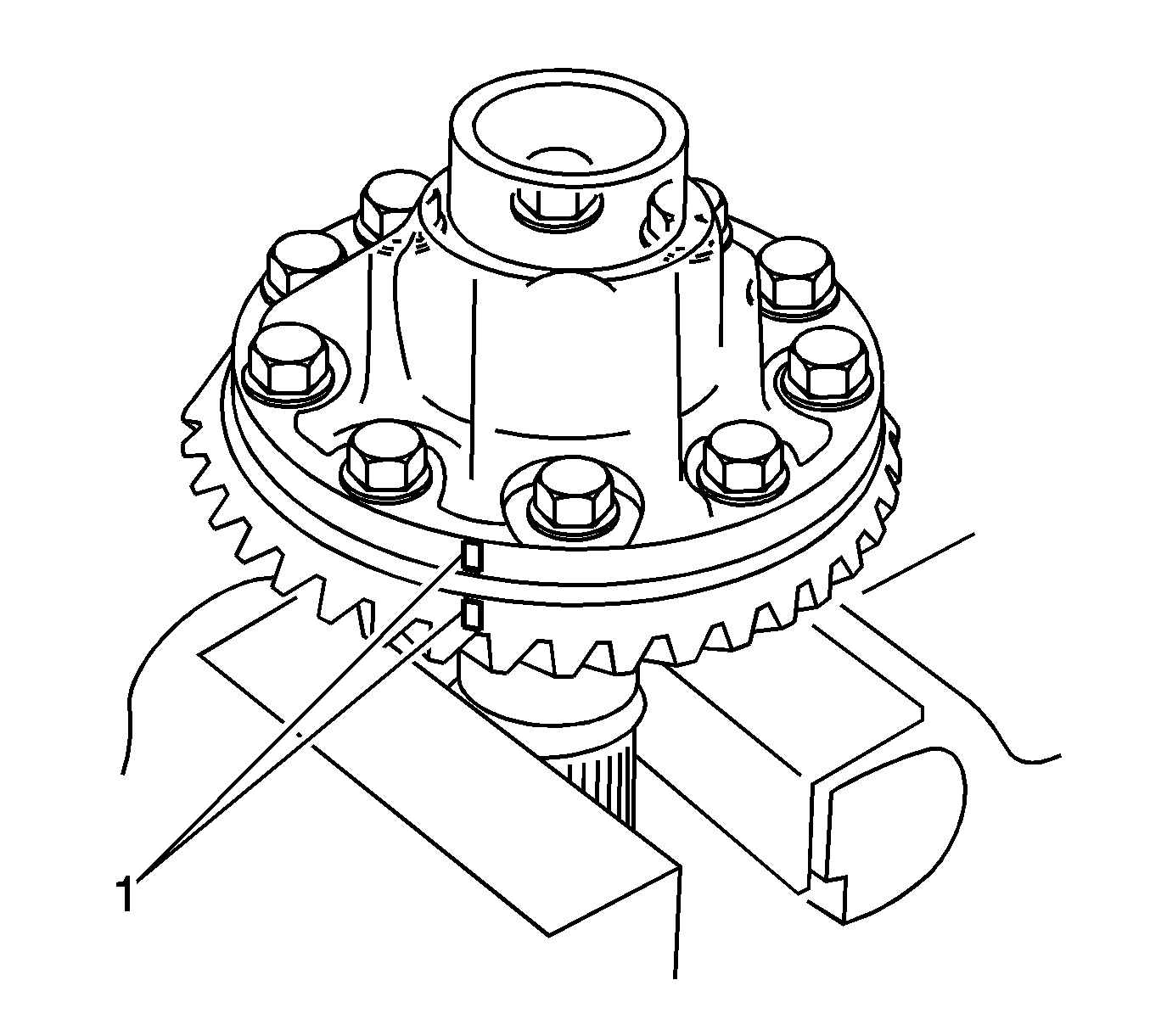
- Place alignment marks (1) on the ring gear and the mounting case.
- Remove the 10 ring gear bolts.
- Using a soft faced hammer, tap on the ring gear to separate it from the ring gear mounting case.
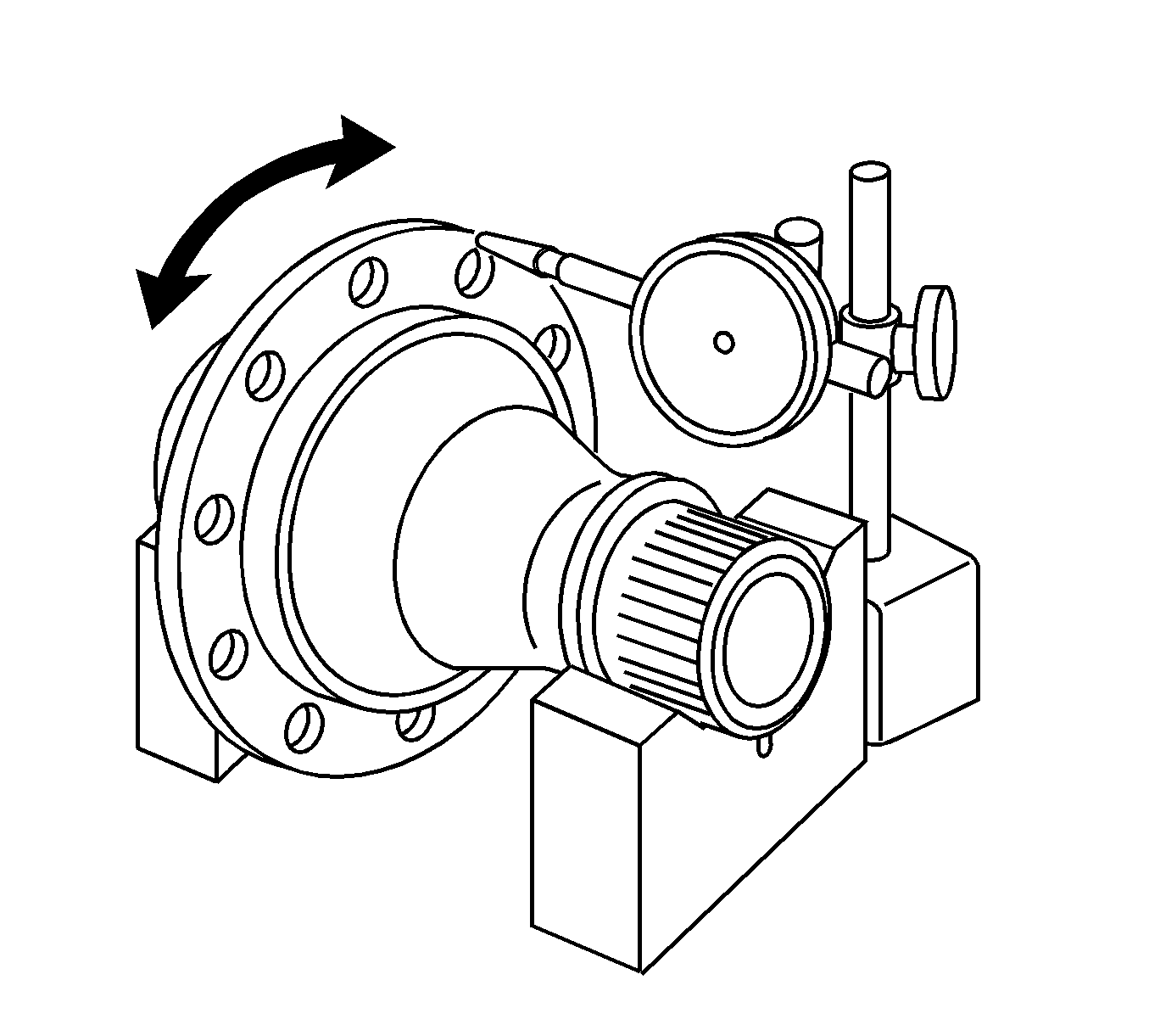
- Using a dial indicator, check the runout of the ring gear mounting case.
- Using a brass bar and hammer, remove the drive pinion bearing race from the transfer case.
Preload
Ring gear and drive pinion preload at starting should
be 0.32-0.57 N·m (2.8-5.0 lb in). Total preload
at starting should be 0.53-0.94 N·m (4.7-8.3 lb in).
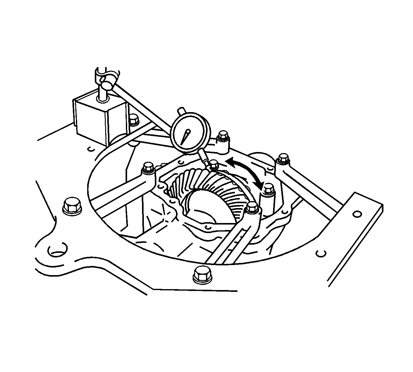
Important: Backlash should be checked in 3 different positions on the ring gear.
Backlash
Backlash should be 0.10-0.15 mm (0.0039-0.0059 in).
Runout
Runout should not exceed 0.06 mm (0.0024 in).

Runout
Runout should not exceed 0.14 mm (0.0055 in).
