|
|---|
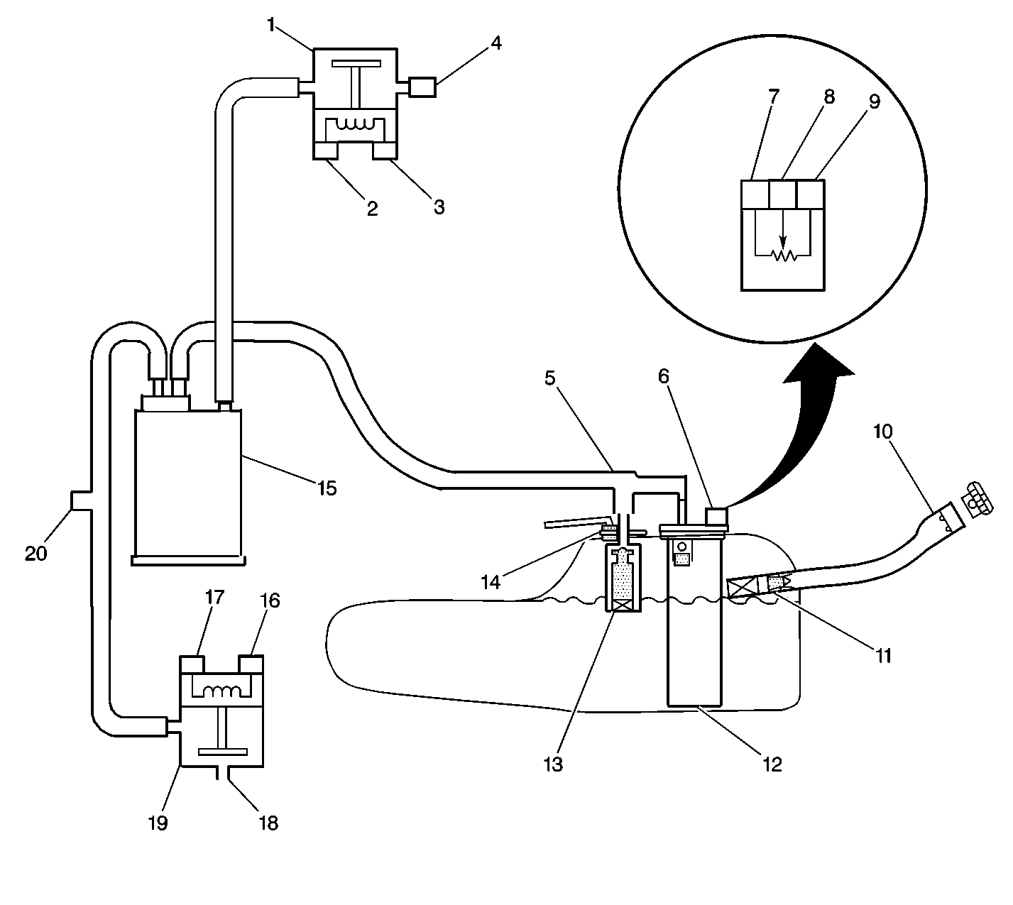
| (1) | EVAP Vent Valve/Solenoid |
| (2) | EVAP
Vent Valve/Solenoid Ignition Feed Circuit Terminal |
| (3) | EVAP Vent Valve/Solenoid Control Circuit
Terminal |
| (4) | EVAP Vent Valve/Solenoid Filter |
| (5) | EVAP Vapor Lines |
| (6) | Fuel Tank
Pressure Sensor |
| (7) | Fuel Tank Pressure Sensor Ground Circuit Terminal |
| (8) | Fuel Tank Pressure Sensor Signal Circuit Terminal |
| (9) | Fuel Tank Pressure Sensor Circuit
5 Volt Reference Circuit Terminal |
| (10) | Fuel Filler Pipe |
| (11) | Check Valve
(Spitback) |
| (12) | Modular Fuel Sender Assembly |
| (13) | Fuel Limiter Vent Valve (FLVV) |
| (14) | Pressure/Vacuum Relief Valve (Optional) |
| (15) | EVAP Canister |
| (16) | EVAP Canister Purge Valve/Solenoid
Ignition Feed Circuit Terminal |
| (17) | EVAP Canister Purge Valve/Solenoid Control
Circuit Terminal |
| (18) | Intake Manifold Vacuum Source |
| (19) | EVAP Canister Purge Valve/Solenoid |
| (20) | EVAP Service Port |
The Control Module then monitors the ability of the system to maintain
the vacuum. If the vacuum remains for a specified period of time, then there
are no evaporative leaks, and a PASS report is sent to the control module.
If there is a leak, the system either will not achieve a vacuum, or a vacuum
cannot be maintained. Usually a fault can only be detected after a cold start
with a trip of sufficient length and driving conditions to run the needed
tests. The enhanced evaporative system diagnostic conducts up to 8 specific
sub-tests in order to detect the fault conditions. If the diagnostic fails
a sub-test, the Control Module stores a Diagnostic Trouble Code (DTC) in order
to indicate the type of fault detected.