Frontal Restraint Devices
The frontal Supplemental Inflatable Restraint (SIR) system supplements
the protection offered by the driver and front passenger seat belts. The
frontal SIR system deploys an air bag from the center of the steering wheel
and from the right side of the instrument panel.
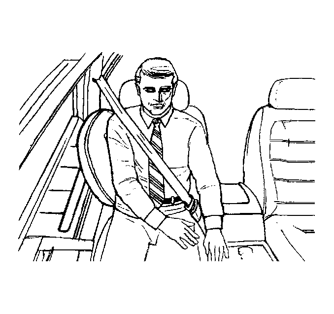
The seat belt pretensioners remove slack from the driver and passenger
front seat belts during a frontal impact. The frontal SIR system deploys
the seat belt pretensioners with the frontal air bags.
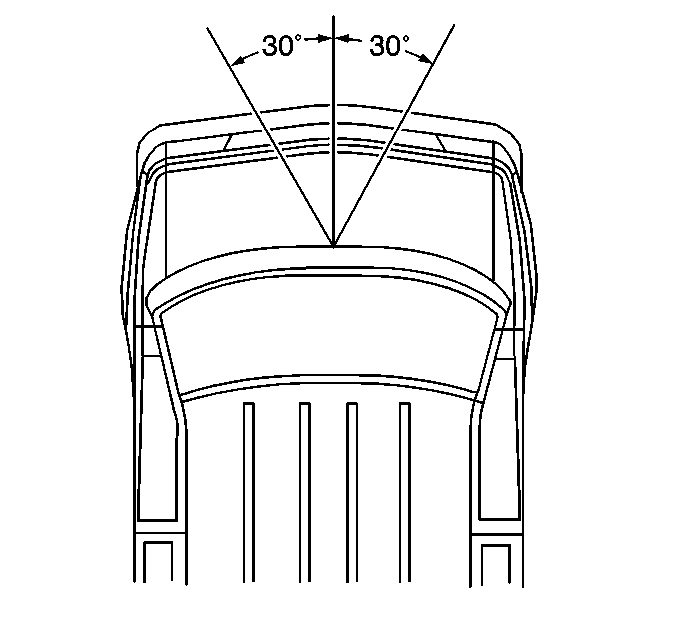
A frontal crash of sufficient force up to 30 degrees off the
longitudinal centerline of the vehicle will deploy the frontal air bags and
the pretensioners. The knee bolsters absorb crash energy. The driver and
passenger knee bolsters are below the instrument panel.
Frontal SIR System Description
The frontal SIR system consists of the following components:
| • | Inflatable Restraint Sensing and Diagnostic Module (SDM) |
| • | Inflatable Restraint Steering Wheel Module |
| • | Inflatable Restraint Steering Wheel Module Coil |
| • | Inflatable Restraint IP Module |
| • | Inflatable Restraint Side Impact Module - Left |
| • | Inflatable Restraint Side Impact Module - Right |
| • | Seat Belt Pretensioner - LF |
| • | Seat Belt Pretensioner - RF |
| • | Inflatable Restraint Side Impact Sensors |
| • | AIR BAG Indicator in the Instrument Panel Cluster |
The inflatable restraint sensing and diagnostic module (SDM), inflatable
restraint steering wheel module coil, inflatable restraint steering wheel
module, inflatable restraint IP module, seat belt pretensioner - LF, seat
belt pretensioner - RF, and the connecting wires make up the frontal deployment
loops. The function of the frontal deployment loops is to supply current
through the frontal inflator modules and the pretensioners to cause deployment
in the event of a mild-to-severe frontal collision. Deployment occurs when
the SDM detects vehicle velocity changes severe enough to warrant deployment.
The SDM contains a sensing device (accelerometer) that converts vehicle
velocity changes to an electrical signal. The SDM compares this electrical
signal to a value stored in memory. When the generated signal exceeds the
stored value, the SDM performs additional signal processing and compares
the generated signals to values stored in memory. When two of the generated
signals exceed the stored values, the SDM will allow current to flow through
the frontal inflator modules and the pretensioners causing deployment.
Side Impact Restraint Devices
The side impact air bag system supplements the protection offered by
the driver door, the front passenger door, and the vehicle structure. The
side impact air bag system deploys an air bag from the side of the driver
or front passenger seat. A side crash of sufficient force will deploy a side
air bag.
Side Impact Air Bag System Description
The side impact air bag system consists of the following components:
| • | 2 Inflatable Restraint Side Impact Sensors (SIS) (1 in each B-pillar) |
| • | An Inflatable Restraint Side Impact Module - Left in the driver's
seat |
| • | An Inflatable Restraint Side Impact Module - Right in the front
passenger's seat |
| • | An AIR BAG Indicator in the Instrument Panel Cluster |
| • | An Inflatable Restraint Sensing and Diagnostic Module (SDM) |
The inflatable restraint side impact sensor (SIS), the inflatable restraint
side impact modules, and the connecting wires make up the side impact deployment
loops. The function of the side impact deployment loop is to supply current
through the side impact inflator module, which will cause deployment of the
side impact air bag. Deployment occurs when one of the SIS's detects a side
impact severe enough to warrant deployment.
The SIS contains a sensing device (accelerometer) that converts acceleration
into an electrical (analog) signal. This signal is converted by a microprocessor
in the SIS into acceleration and velocity data. This data is used by a sensing
algorithm and compared to various predetermined boundary conditions. When
the acceleration value exceeds the predetermined threshold, and the velocity
boundary is crossed, the SIS will cause current to flow through the inflatable
restraint side impact module - left or the inflatable restraint side impact
module - right.
Component Description
Inflatable Restraint Sensing and Diagnostic Module (SDM)
The SDM performs the following functions in the SIR system:
| • | Energy Reserve - The SDM maintains 12-16 Volt Loop
Reserve (VLR) energy supplies to provide deployment energy for the frontal
air bags. Ignition voltage can provide deployment energy if the 12-16
Volt Loop Reserves malfunction. |
| • | Frontal Crash Detection - The SDM monitors vehicle velocity
changes to detect frontal crashes that are severe enough to warrant deployment. |
| • | Frontal Air Bag Deployment - During a frontal crash of sufficient
force, the SDM will cause enough current to flow through the frontal inflator
modules to deploy the frontal air bags. |
| • | Seat Belt Pretensioner Deployment - During a frontal crash
of sufficient force, the SDM will cause current to flow through the seat
belt pretensioners in order to cause deployment. |
| • | Frontal Crash Recording - The SDM records information regarding
the SIR system status during a frontal crash. |
| • | Side Impact System Malfunction Monitoring - The SDM monitors
a diagnostic line from each inflatable restraint side impact sensor (SIS).
Both SIS's communicate the status of the side impact air bag system to the
SDM. |
| • | Side Air Bag Deployment - During a side crash of sufficient
force, the SDM will cause enough current to flow through one of the side
inflator modules to deploy the side air bag. |
| • | Malfunction Detection - The SDM performs diagnostic monitoring
of the SIR system electrical components. Upon detection of a circuit malfunction,
the SDM will set a Diagnostic Trouble Code (DTC). |
| • | Malfunction Diagnosis - The SDM displays SIR Diagnostic
Trouble Codes and system status information through the use of a scan tool. |
| • | Driver Notification - The SDM warns the vehicle driver of
SIR system malfunctions by controlling the AIR BAG indicator. |
The SDM connects to the SIR wiring harness using a 45-way connector.
The SDM receives power whenever the ignition switch is in the ON or
START positions.
Inflatable Restraint Side Impact Sensor (SIS)
The SIS's are crash-sensing devices used in the detection of side impact
collisions. The SIS - Left is located in the LH B-pillar. The SIS - Right
is located in the RH B-pillar. The SIS's are used to perform the following
functions:
| • | Side Impact Crash Detection - Each SIS monitors vehicle
velocity changes to detect side impact crashes that are severe enough to
warrant deployment. |
| • | Side Air Bag System Status Communication - The SDM monitors
a diagnostic line from each SIS. Both SIS's communicate the status of the
side impact air bag system to the SDM over these diagnostic lines. |
The SIS connects to the air bag wiring harness using a 4-way connector.
The SIS receives power via the SDM whenever the ignition switch is in
the ON or START positions.
AIR BAG Indicator
The AIR BAG indicator is represented by an icon graphic. Ignition voltage
is applied to the AIR BAG indicator when the ignition switch is turned to
the ACC or ON positions. The SDM controls the lamp by providing ground to
the AIR BAG indicator control circuit. The SIR system uses the AIR BAG indicator
to do the following:
| • | Verify the indicator operation by illuminating the lamp for approximately
6 seconds when the ignition switch is first turned to the ACC or ON position. |
| • | Warn the vehicle driver of SIR system malfunctions which could
potentially affect the operation of the system. These malfunctions could
result in 1 or more of the following conditions: |
| - | Non-deployment of the frontal air bags and/or seat belt pretensioners
in the case of a frontal crash |
| - | Non-deployment of a side air bag in the case of a side impact
crash |
| - | Deployment for conditions less severe than intended |
The AIR BAG indicator is the key to driver notification of SIR system
malfunctions.
Inflatable Restraint Steering Wheel Module Coil
The steering wheel module coil consists of 2 or more current-carrying
coils. The steering wheel module coil attaches to the steering column. 2
of the current-carrying coils allow rotation of the steering wheel while maintaining
continuous contact of the driver deployment loop to the steering wheel module.
There is a shorting bar on the steering wheel module coil connector.
The shorting bar shorts the circuits to the steering wheel module coil and
steering wheel module during the disconnection of the connector. The shorting
of the steering wheel module coil and steering wheel module circuitry will
help prevent unwanted deployment of the air bag when servicing the steering
column or other SIR system components.
Inflator Modules
The inflator modules consist of an inflatable bag and an inflator. An
inflator consists of a canister of gas-generating material and an initiating
device. The initiator is part of the deployment loop. When the vehicle is
in a frontal crash of sufficient force, the SDM causes current to flow through
the frontal air bag deployment loops. When the vehicle is in a side impact
crash of sufficient force, the SIS causes current to flow through the side
impact air bag deployment loops. Current passing through the initiator ignites
the material in the inflator module. The gas produced from this reaction
rapidly inflates the air bag.
There are shorting bars located on the steering wheel module connector,
the IP module connector, the side impact module connectors, the seat belt
pretensioner connectors, and the SDM connectors. The shorting bars will short
across the deployment loop circuits during the disconnection of the connector.
The shorting of the circuitry will help prevent unwanted deployment of the
air bag or pretensioner when servicing the vehicle.
Seat Belt Pretensioners
The seat belt pretensioner assembly consists of the following components:
| • | A routing cable with piston |
When the vehicle is in a frontal crash of sufficient force, the SDM
causes current to flow through the frontal air bag deployment loops and the
pretensioner deployment loops. Current passing through the initiator ignites
the material in the pretensioner gas generator. The gas produced from this
reaction rapidly shortens the seat belt buckle height. The seat belt pretensioners
will deploy immediately before the frontal air bags deploy in the event of
a mild-to-severe frontal collision.
Steering Column
The steering column is energy absorbing. The steering column can compress
during a frontal crash in order to decrease the chance of injury to the driver.
Knee Bolster
The knee bolsters absorb energy and control the forward movement of
the vehicle's front seat occupants during a frontal crash, by limiting leg
movement.
