For 1990-2009 cars only
Removal Procedure
- Remove the 2 master cylinder nuts.
- Position the master cylinder aside and support with heavy mechanics wire or equivalent.
- Remove the steering column from the vehicle. Refer to Steering Column Replacement .
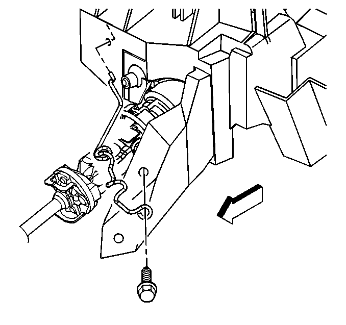
- Remove the transmission range selector cable support bolt from the instrument panel (I/P) reinforcement brace.
- Disconnect the electrical connectors from the following components:
- Remove the accelerator pedal position sensor assembly. Refer to Accelerator Pedal Position Sensor Replacement .
- Remove the left side floor air outlet duct. Refer to Floor Air Outlet Duct Replacement - Left Side .
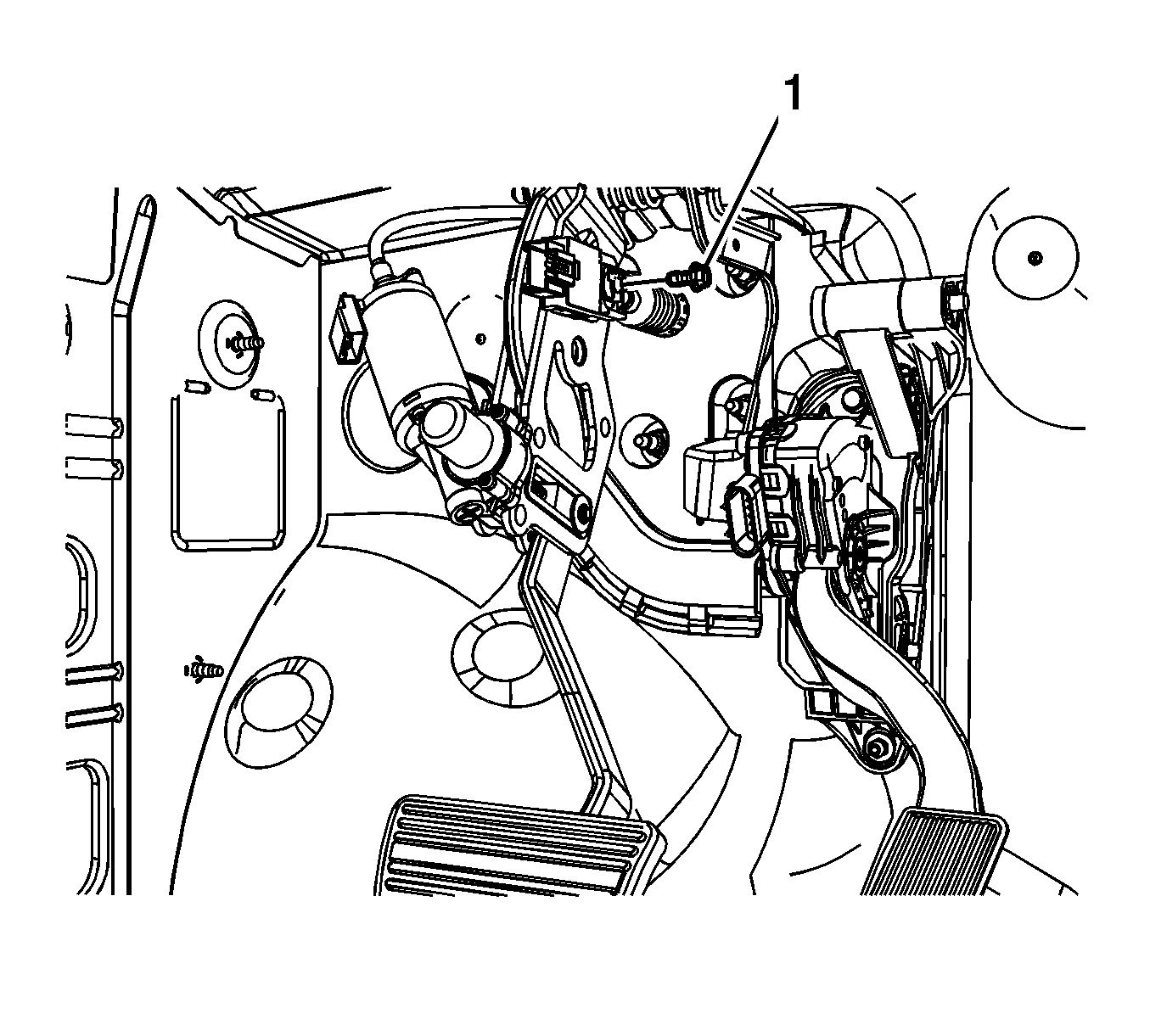
- Remove the brake booster pushrod retainer bolt (1).
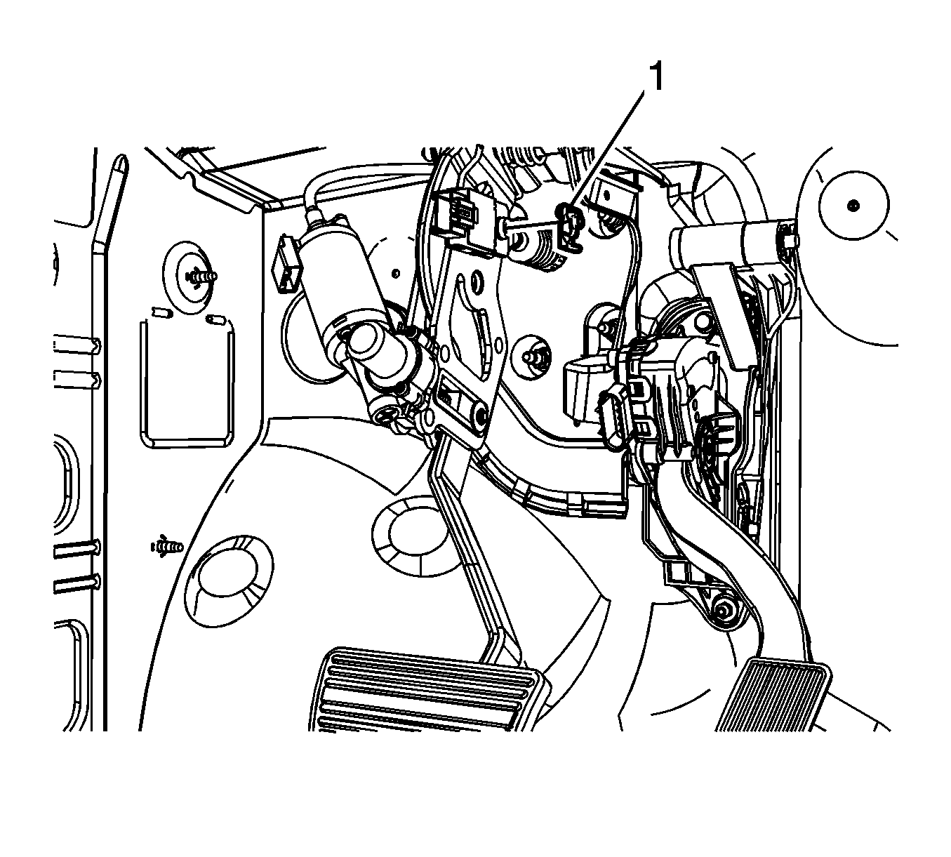
- Remove the brake booster pushrod retainer (1).
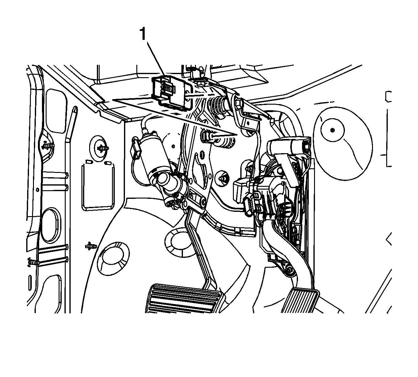
- Remove the stoplamp switch (1).
- Disconnect the brake booster pushrod from the brake pedal pivot.
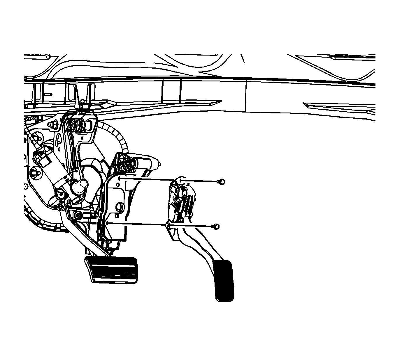
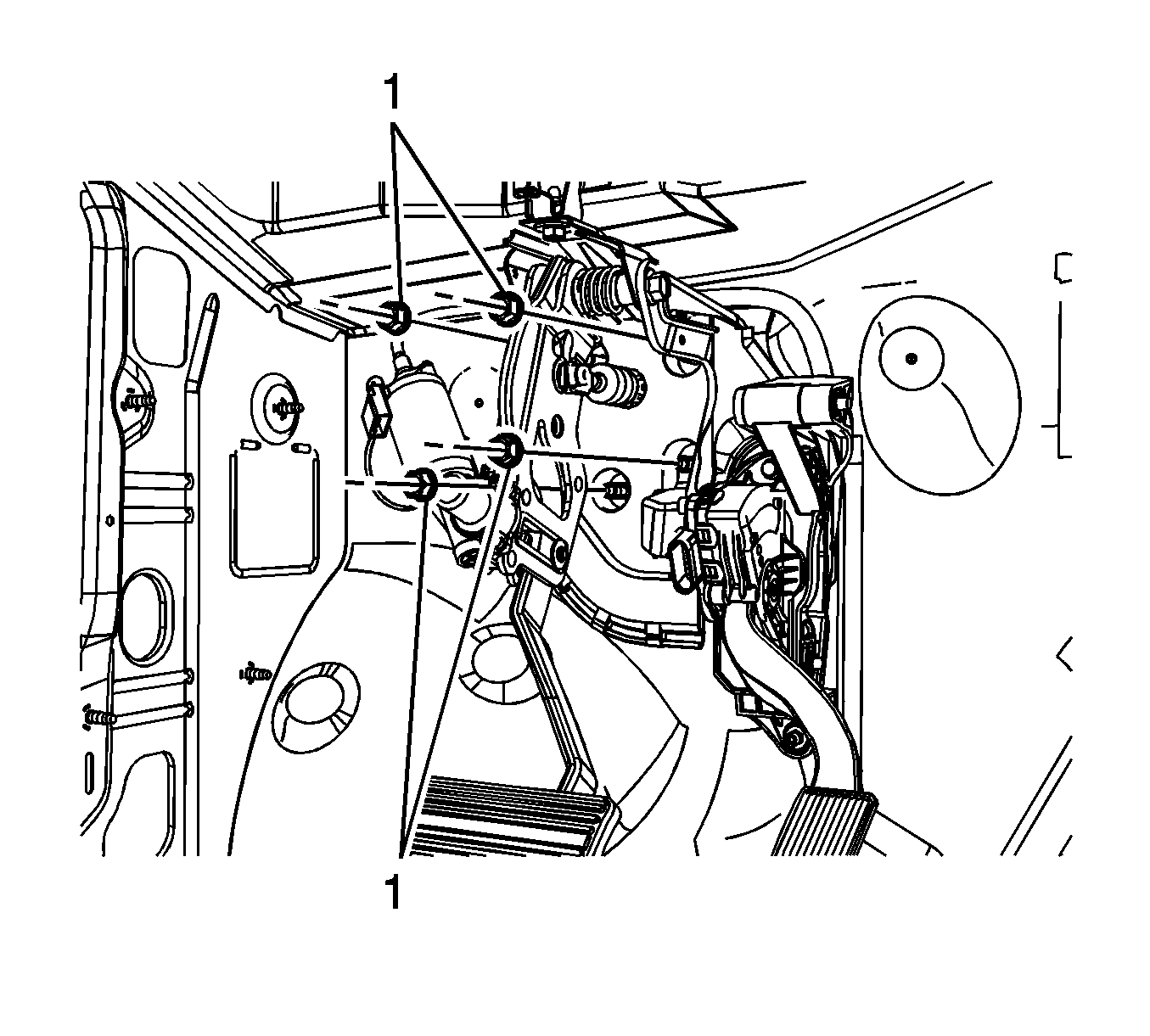
- Remove the adjustable pedal bracket nuts (1).
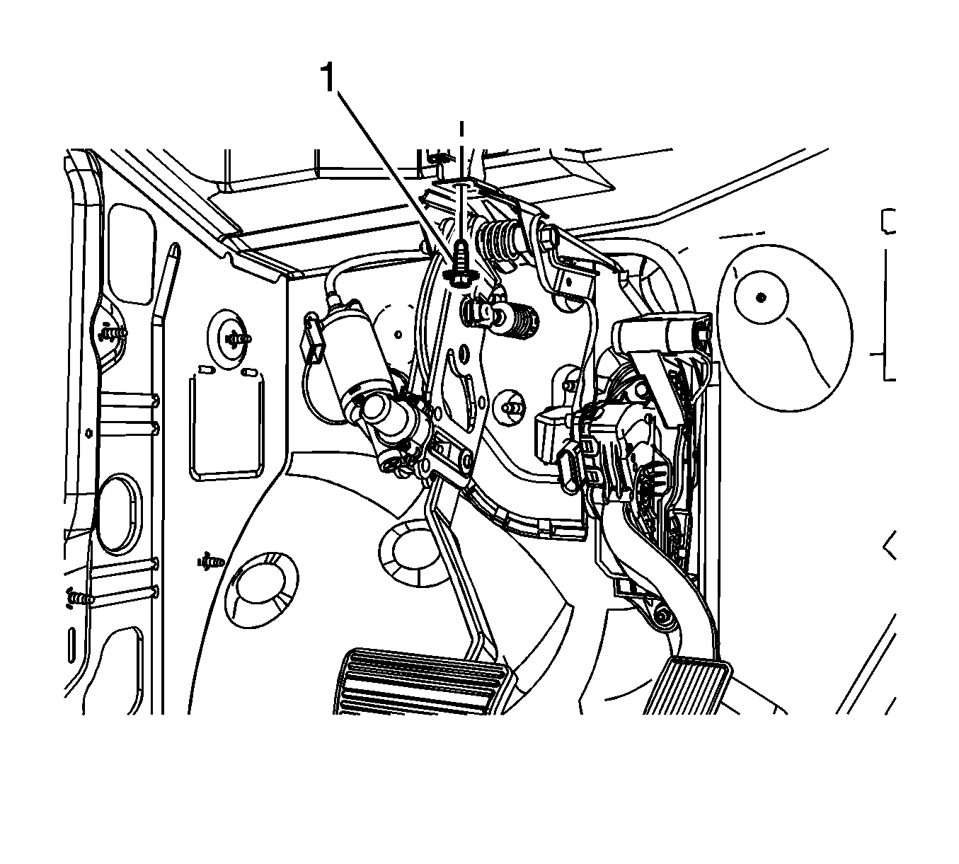
- Remove the adjustable pedal bracket bolt (1).
- Position the brake booster forward until the studs are past the adjustable pedal bracket holes.
- Remove the adjustable pedal assembly from the vehicle.
Important: DO NOT disconnect the brake pipes from the master cylinder.
| • | The adjustable pedals motor assembly |
| • | The memory sensor connector, if equipped |
| • | The pedal position sensor |
Installation Procedure
- With the aid of an assistant, position the brake booster to the vehicle.
- Install the adjustable pedal assembly to the vehicle.
- Hand install the adjustable pedal bracket bolt (1).
- Install the adjustable pedal bracket nuts (1).
- Tighten the adjustable pedal bracket bolt.
- Apply a thin coat of high temperature grease GM P/N 12345994 (Canadian P/N 10953501) to the pushrod pin on the brake pedal.
- Connect the brake booster pushrod to the brake pedal pivot.
- Install the stoplamp switch (1).
- Install the brake booster pushrod retainer (1).
- Install the brake booster pushrod retainer bolt (1).
- Install the accelerator pedal position sensor assembly. Refer to Accelerator Pedal Position Sensor Replacement .
- Connect the electrical connectors to the following components:
- Install the transmission range selector cable support bolt to the I/P reinforcement brace.
- Install the steering column to the vehicle. Refer to Steering Column Replacement .
- Install the left side floor air outlet duct. Refer to Floor Air Outlet Duct Replacement - Left Side .
- Install the master cylinder to the brake booster.
- Install the 2 master cylinder nuts.
- Verify the correct operation of the adjustable pedals.

Important: Do not tighten the adjustable pedal bracket bolt until the adjustable pedal bracket nuts are installed.
Notice: Refer to Fastener Notice in the Preface section.

Tighten
Tighten the nuts to 25 N·m (18 lb ft).
Tighten
Tighten the bolt to 36 N·m (27 lb ft).


Rotate the retainer 360 degrees to ensure it is seated properly before tightening the retainer bolt.

Tighten
Tighten the bolt to 10 N·m (89 lb in).
| • | The adjustable pedals motor assembly |
| • | The memory sensor connector, if equipped |
| • | The pedal position sensor |

Tighten
Tighten the bolt to 10 N·m (89 lb in).
Tighten
Tighten the nuts to 33 N·m (24 lb ft).
