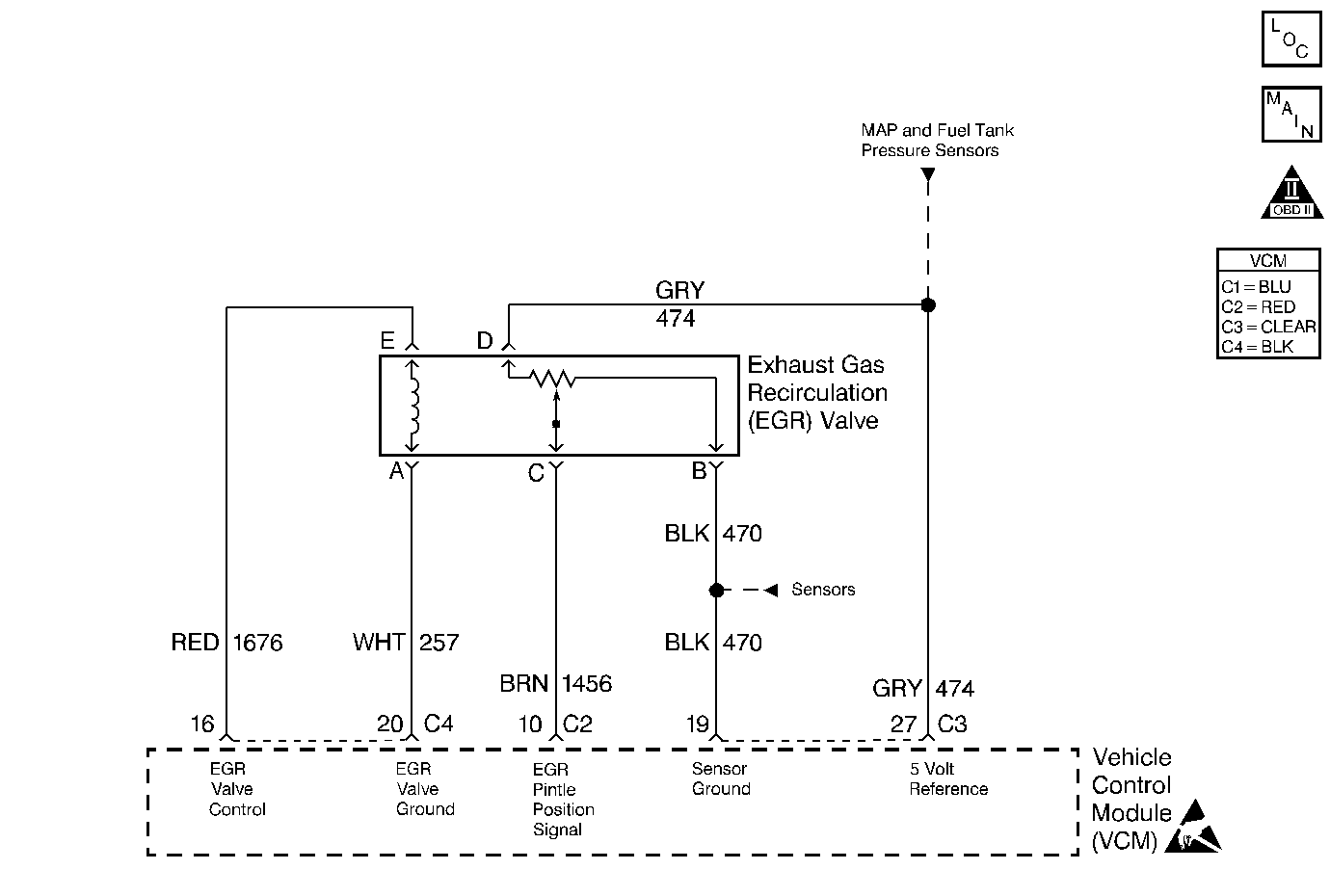
In order to control the Exhaust Gas Recirculation (EGR), the control
module operates the linear EGR valve. The linear EGR valve is a small motor
with a pintle that is normally closed. By providing a ground path, the control
module will open the pintle and allow the exhaust gasses to pass through the
valve. The control module of the EGR is based on the following inputs:
This chart is used for a malfunctioning valve, plugged EGR passages,
or improper wiring connections.
The numbers below refer to the step numbers in the diagnostic table.
Step 
 | Action 
 | Value(s) 
 | Yes 
 | No 
 | 
1 
 | Was
the Powertrain On-Board Diagnostic (OBD) System Check performed? 
 | -- 
 | 
Go to Step 2
              
 | Go to 
Powertrain On Board Diagnostic (OBD) System Check  
 | 
2
             
 | 
- Set the parking brake and block the drive wheels.
 
- Install the scan tool.
 
- Idle the engine until normal operating temperature is reached.
 
- Check the actual EGR position with the scan tool.
 
 
Does the scan tool indicate more than the specified value? 
 | 0% 
 | 
Go to Step 4
              
 | 
Go to Step
3
              
 | 
3
              
 | 
- Turn On the ignition leaving the engine OFF.
 
- Command ON the EGR valve to the specified value using the scan
tool.
 
 
Does the actual EGR position follow the commanded EGR position? 
 | 100% 
 | 
Go to Step 17
              
 | 
Go to Step 6
              
 | 
4 
 | Disconnect the EGR valve harness
connector. 
Does the scan tool indicate the actual EGR position above the specified
value? 
 | 0% 
 | 
Go to Step 16
                  
 | 
Go to Step 5
               
 | 
5
             
 | 
- Turn OFF the ignition 
 
- Connect a test lamp between the EGR valve feed control circuit
and the EGR valve ground circuit at the EGR harness connector.
 
- Turn ON the ignition leaving the engine OFF.
 
 
Is the test lamp ON? 
I 
 | -- 
 | 
Go to Step 15
              
 | 
Go to Step 10
              
 | 
6
              
 | 
- Turn ON the ignition leaving the engine OFF.
 
- Connect a test lamp between the EGR valve feed control circuit
and the EGR valve ground circuit at the EGR harness connector.
 
- Command ON the EGR valve using the scan tool to the specified
value.
 
 
Is the test lamp ON?  
 | 100% 
 | 
Go to Step
13
              
 | 
Go to Step
7
                  
 | 
7 
 | 
- Turn OFF the ignition.
 
- Probe the EGR valve ground circuit with a test lamp connected
to B+.
 
 
Is the test lamp ON? 
 | -- 
 | 
Go to Step
8
              
 | 
Go to Step 9
   
              
 | 
8 
 | Check the EGR valve feed control circuit for an open. 
Did you find a problem? 
 | -- 
 | 
Go to Step
22
              
 | 
Go to Step
21
                  
 | 
9 
 | Check the EGR valve ground circuit for the following conditions: 
Did you find a problem? 
 | -- 
 | 
Go to Step
22
              
 | 
Go to Step
21
                  
 | 
10 
 | 
- Turn ON the ignition leaving the engine off.
 
- Probe the EGR 5 V reference circuit at the EGR valve harness
connector with a J 39200 
   DMM connected to a ground.
 
 
Is the voltage above the specified value? 
 | 5.2 V 
 | 
Go to Step 22
              
 | 
Go to Step
11
              
 | 
11 
 | 
- Turn OFF the ignition.
 
- Probe the EGR sensor ground circuit at the EGR valve harness connector
with a test lamp connected to B+.
 
 
Is the test lamp ON?  
 | -- 
 | 
Go to Step
19
              
 | 
Go to Step
12
                  
 | 
12 
 | 
- Turn OFF the ignition.
 
- Disconnect the VCM C4 connector.
 
- Check the EGR sensor ground circuit for an open.
 
 
Did you find a problem? 
 | -- 
 | 
Go to Step
22
              
 | 
Go to Step
21
                  
 | 
13 
 | 
- Turn ON the ignition leaving the engine OFF. 
 
- Probe the EGR 5 V reference circuit at the EGR valve harness
connector with a J 39200 
   DMM connected to a ground.
 
 
Is the voltage near the specified value? 
 | 5.2 V 
 | 
Go to Step 14
              
 | 
Go to Step
22
              
 | 
14 
 | 
- Disconnect the EGR valve harness connector. 
 
- Install a jumper between the 5 V reference circuit and
the EGR pintle position signal circuit at the EGR valve harness connector.
 
- Turn ON the ignition leaving the engine OFF.
 
 
Is the actual EGR position near the specified value? 
 | 100 % 
 | 
Go to Step 19
              
 | 
Go to Step 20
              
 | 
15 
 | 
- Disconnect the VCM C4 connector .
 
- Turn ON the ignition leaving the engine OFF.
 
- Check the EGR valve feed control circuit for a short to voltage.
 
 
Did you find a problem? 
 | -- 
 | 
Go to Step
22
              
 | 
Go to Step
23
                  
 | 
16 
 | 
- Disconnect the VCM C2 connector.
 
- Turn ON the ignition leaving the engine OFF.
 
- Check the EGR pintle position signal circuit for a short to voltage.
 
 
Did you find a problem? 
 | -- 
 | 
Go to Step
22
              
 | 
Go to Step
23
                 
 | 
17 
 | 
- Start the engine .
 
- Observe the MAP sensor reading.
 
- Command ON the EGR valve to the specified value.
 
- Observe the MAP sensor reading. 
 
 
Does the MAP sensor reading go higher? 
 | 30 % 
 | 
Go to Step 24
               
 | 
Go to Step
18
              
 | 
18 
 | Repair the blockage in the EGR valve passages. 
Is the action complete? 
 | -- 
 | 
Go to Step
24
              
 | -- 
 | 
19 
 | Replace the EGR valve. Refer to 
Exhaust Gas Recirculation Valve Replacement 
. 
Is the action complete? 
 | -- 
 | 
Go to Step
24
              
 | -- 
 | 
20 
 | Check the EGR pintle position circuit for an open or short
to ground. 
Did you find a problem? 
 | -- 
 | 
Go to Step
22
              
 | 
Go to Step
21
                 
 | 
21 
 | Check for a poor connection at the VCM connectors. 
Did you find a problem? 
 | -- 
 | 
Go to Step
22
              
 | 
Go to Step
23
                 
 | 
22 
 | Repair the circuit as necessary. Refer to
Wiring Repairs 
 or 
Connector Repairs 
in Wiring Systems. 
Is the action complete? 
 | -- 
 | 
Go to Step
24
              
 | -- 
 | 
23 
 | 
- Replace the VCM.
 
- Program the new VCM. Refer to 
VCM Replacement/Programming 
.
 
- Perform the VTD Password Learn Procedure. Refer to 
Password Learn 
.
 
- Perform the CKP System Variation Learn Procedure. Refer to 
Crankshaft Position System Variation Learn 
.
 
 
Is the action complete? 
 | -- 
 | 
Go to Step
24
              
 | -- 
 | 
24 
 | 
- Set the parking brake and block the drive wheels. 
 
- Install the scan tool.
 
- Idle the engine until normal operating temperature is reached.
 
- Command ON and OFF the EGR using the scan tool.
 
 
Does the actual EGR position follow the commanded EGR position? 
 | -- 
 | System OK 
 | 
Go to Step 2
              
 |