| |||||||
|---|---|---|---|---|---|---|---|
Connector Part Information |
| ||||||
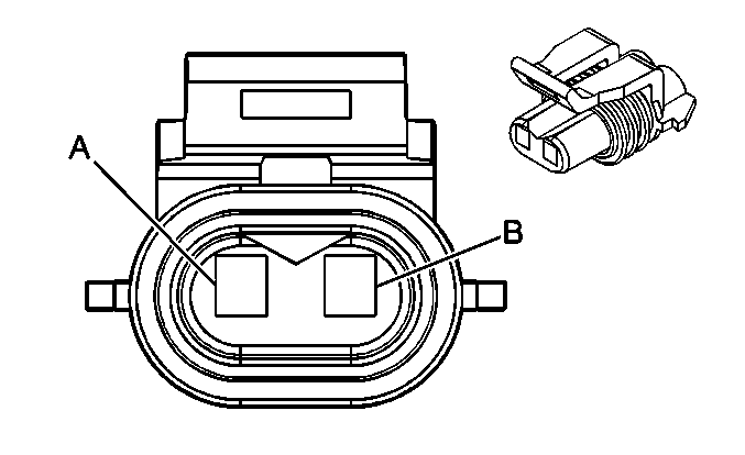
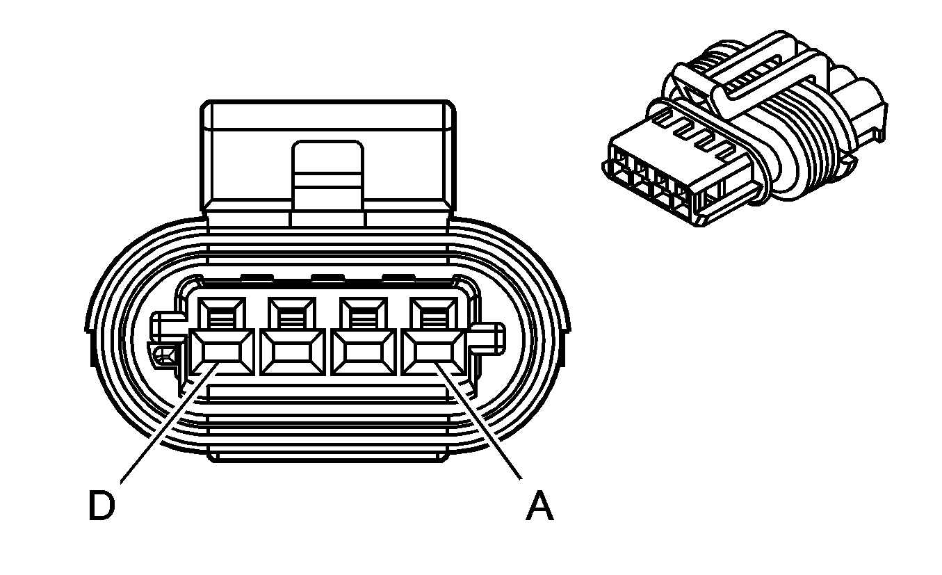
Pin | Wire Color | Circuit No. | Function | ||||
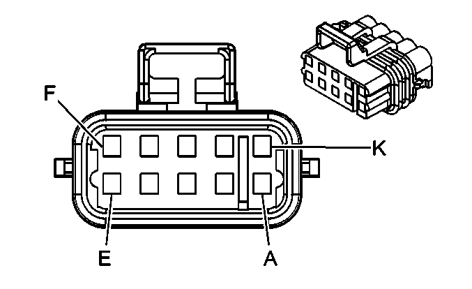
A | -- | -- | Not Used | ||||
B | PU | 1272 | 5-Volt Reference | ||||
C | L-BU | 1162 | APP Sensor 2 Signal | ||||
D | TN | 1274 | Low Reference | ||||
E | BN | 1271 | Low Reference | ||||
F | D-BU | 1161 | APP Sensor 1 Signal | ||||
G | WH/BK | 1164 | 5-Volt Reference | ||||
H-K | -- | -- | Not Used | ||||
| |||||||
|---|---|---|---|---|---|---|---|
Connector Part Information |
| ||||||
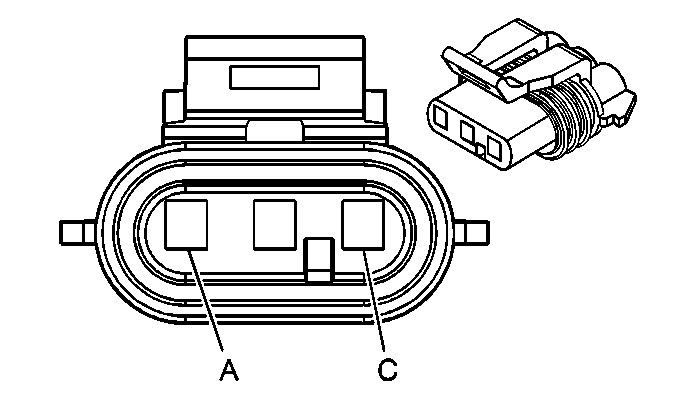
Pin | Wire Color | Circuit No. | Function | ||||
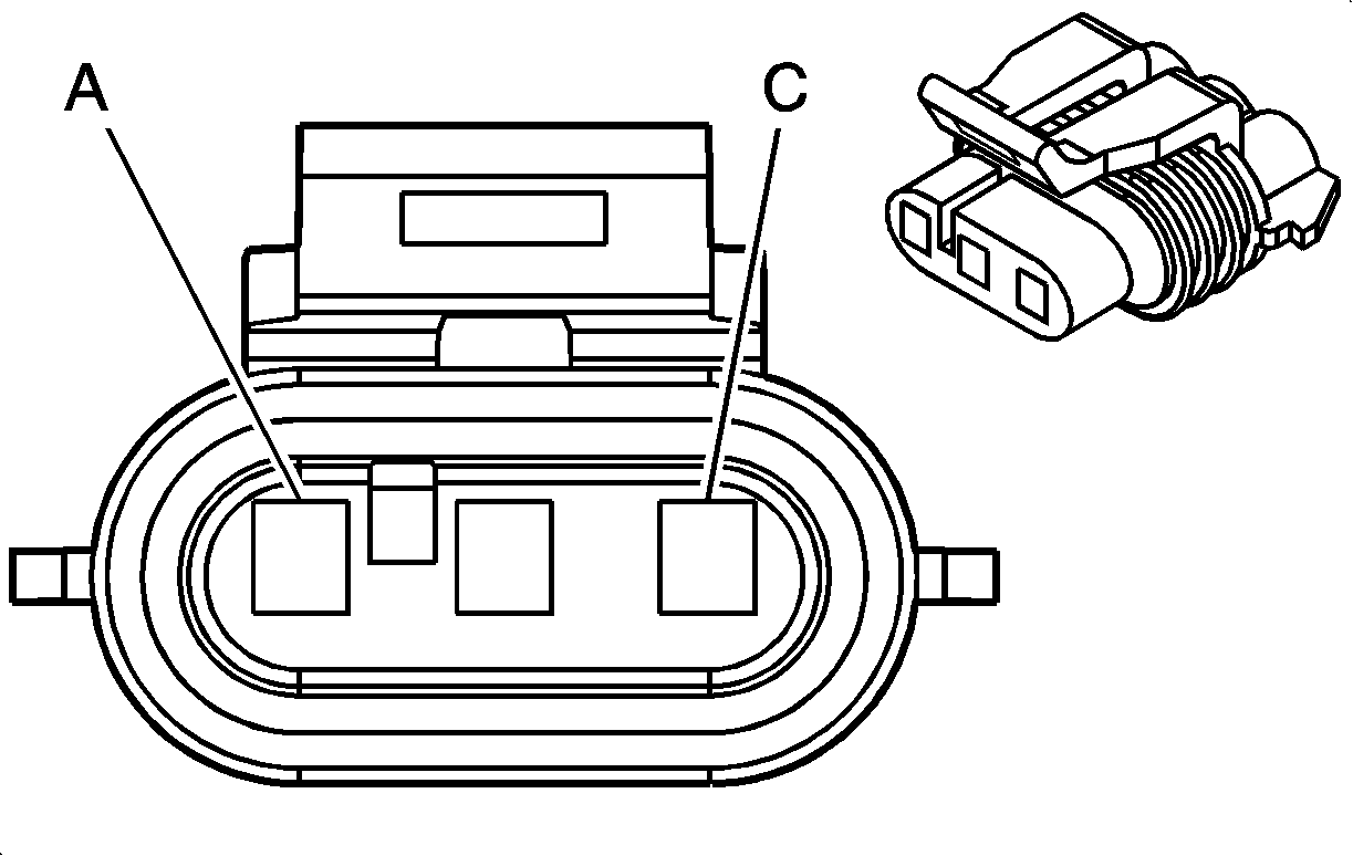
A | BN/WH | 633 | CMP Sensor Signal | ||||
B | PK/BK | 632 | Low Reference | ||||
C | RD | 631 | 12-Volt Reference | ||||
| |||||||
|---|---|---|---|---|---|---|---|
Connector Part Information |
| ||||||
Pin | Wire Color | Circuit No. | Function | ||||
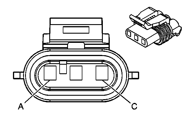
A | D-BU/WH | 1869 | CKP Sensor Signal | ||||
B | YE/BK | 1868 | Low Reference | ||||
C | L-GN | 1867 | 12-Volt Reference | ||||
| |||||||
|---|---|---|---|---|---|---|---|
Connector Part Information |
| ||||||
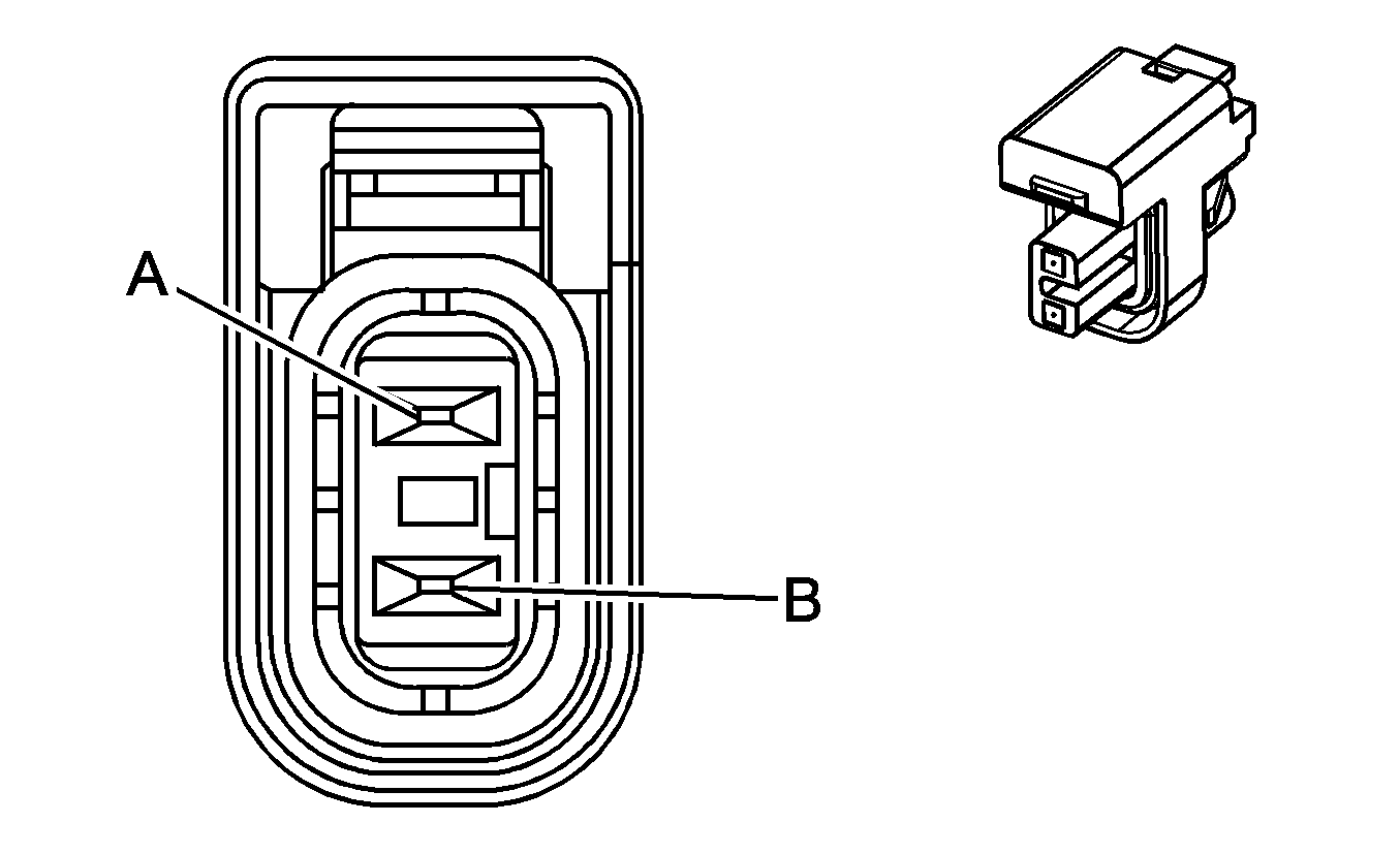
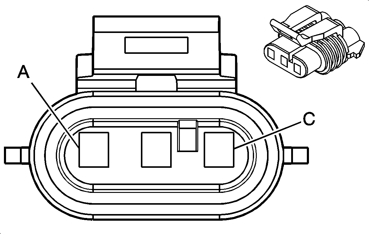
Pin | Wire Color | Circuit No. | Function | ||||
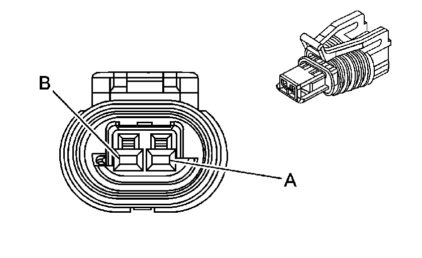
A | BK | 407 | Low Reference | ||||
B | YE | 410 | ECT Sensor Signal | ||||

| |||||||
|---|---|---|---|---|---|---|---|
Connector Part Information |
| ||||||
Pin | Wire Color | Circuit No. | Function | ||||
A | PK | 439 | Ignition 1 Voltage | ||||
B | D-GN/WH | 428 | EVAP Canister Purge Solenoid Control | ||||
| |||||||
|---|---|---|---|---|---|---|---|
Connector Part Information |
| ||||||
Pin | Wire Color | Circuit No. | Function | ||||
A | WH | 1310 | EVAP Canister Vent Solenoid Control | ||||
B | OG | 2640 | Battery Positive Voltage | ||||
| |||||||
|---|---|---|---|---|---|---|---|
Connector Part Information |
| ||||||
Pin | Wire Color | Circuit No. | Function | ||||
A | WH | 1579 | Fuel Temperature/Composition Signal | ||||
B | PK | 439 | Ignition 1 Voltage | ||||
C | BK | 550 | Ground | ||||
| |||||||
|---|---|---|---|---|---|---|---|
Connector Part Information |
| ||||||
Pin | Wire Color | Circuit No. | Function | ||||
A | PK | 1039 | Ignition 1 Voltage | ||||
B | BK | 1744 | Fuel Injector 1 Control | ||||
| |||||||
|---|---|---|---|---|---|---|---|
Connector Part Information |
| ||||||
Pin | Wire Color | Circuit No. | Function | ||||
A | PK | 1039 | Ignition 1 Voltage | ||||
B | BK | 1744 | Fuel Injector 1 Control | ||||
|
| |||||||
|---|---|---|---|---|---|---|---|
Connector Part Information |
| ||||||
Pin | Wire Color | Circuit No. | Function | ||||
A | PK | 1239 | Ignition 1 Voltage | ||||
B | L-GN/BK | 1745 | Fuel Injector 2 Control | ||||
|
| |||||||
|---|---|---|---|---|---|---|---|
Connector Part Information |
| ||||||
Pin | Wire Color | Circuit No. | Function | ||||
A | PK | 1239 | Ignition 1 Voltage | ||||
B | L-GN/BK | 1745 | Fuel Injector 2 Control | ||||
|
| |||||||
|---|---|---|---|---|---|---|---|
Connector Part Information |
| ||||||
Pin | Wire Color | Circuit No. | Function | ||||
A | PK | 1039 | Ignition 1 Voltage | ||||
B | PK/BK | 1746 | Fuel Injector 3 Control | ||||
|
| |||||||
|---|---|---|---|---|---|---|---|
Connector Part Information |
| ||||||
Pin | Wire Color | Circuit No. | Function | ||||
A | PK | 1039 | Ignition 1 Voltage | ||||
B | PK/BK | 1746 | Fuel Injector 3 Control | ||||
|
| |||||||
|---|---|---|---|---|---|---|---|
Connector Part Information |
| ||||||
Pin | Wire Color | Circuit No. | Function | ||||
A | PK | 1239 | Ignition 1 Voltage | ||||
B | L-BU/BK | 844 | Fuel Injector 4 Control | ||||
|
| |||||||
|---|---|---|---|---|---|---|---|
Connector Part Information |
| ||||||
Pin | Wire Color | Circuit No. | Function | ||||
A | PK | 1239 | Ignition 1 Voltage | ||||
B | L-BU/BK | 844 | Fuel Injector 4 Control | ||||
|
| |||||||
|---|---|---|---|---|---|---|---|
Connector Part Information |
| ||||||
Pin | Wire Color | Circuit No. | Function | ||||
A | PK | 1039 | Ignition 1 Voltage | ||||
B | BK/WH | 845 | Fuel Injector 5 Control | ||||
|
| |||||||
|---|---|---|---|---|---|---|---|
Connector Part Information |
| ||||||
Pin | Wire Color | Circuit No. | Function | ||||
A | PK | 1039 | Ignition 1 Voltage | ||||
B | BK/WH | 845 | Fuel Injector 5 Control | ||||
|
| |||||||
|---|---|---|---|---|---|---|---|
Connector Part Information |
| ||||||
Pin | Wire Color | Circuit No. | Function | ||||
A | PK | 1239 | Ignition 1 Voltage | ||||
B | YE/BK | 846 | Fuel Injector 6 Control | ||||
|
| |||||||
|---|---|---|---|---|---|---|---|
Connector Part Information |
| ||||||
Pin | Wire Color | Circuit No. | Function | ||||
A | PK | 1239 | Ignition 1 Voltage | ||||
B | YE/BK | 846 | Fuel Injector 6 Control | ||||
|
| |||||||
|---|---|---|---|---|---|---|---|
Connector Part Information |
| ||||||
Pin | Wire Color | Circuit No. | Function | ||||
A | PK | 1039 | Ignition 1 Voltage | ||||
B | RD/BK | 877 | Fuel Injector 7 Control | ||||
|
| |||||||
|---|---|---|---|---|---|---|---|
Connector Part Information |
| ||||||
Pin | Wire Color | Circuit No. | Function | ||||
A | PK | 1039 | Ignition 1 Voltage | ||||
B | RD/BK | 877 | Fuel Injector 7 Control | ||||
|
| |||||||
|---|---|---|---|---|---|---|---|
Connector Part Information |
| ||||||
Pin | Wire Color | Circuit No. | Function | ||||
A | PK | 1239 | Ignition 1 Voltage | ||||
B | D-BU/WH | 878 | Fuel Injector 8 Control | ||||
|
| |||||||
|---|---|---|---|---|---|---|---|
Connector Part Information |
| ||||||
Pin | Wire Color | Circuit No. | Function | ||||
A | PK | 1239 | Ignition 1 Voltage | ||||
B | D-BU/WH | 878 | Fuel Injector 8 Control | ||||
| |||||||
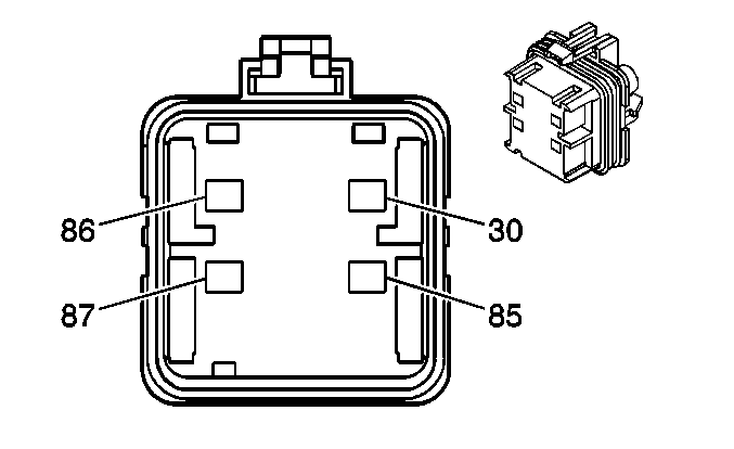
|---|---|---|---|---|---|---|---|
Connector Part Information |
| ||||||
Pin | Wire Color | Circuit No. | Function | ||||
30 | PK | 139 | Ignition 1 Voltage | ||||
85 | GY | 120 | Fuel Pump Supply Voltage | ||||
86 | TN | 1465 | Fuel Pump Relay Control - Secondary | ||||
87 | L-GN | 1058 | Fuel Balance Pump Supply Voltage | ||||
|
| |||||||
|---|---|---|---|---|---|---|---|
Connector Part Information |
| ||||||
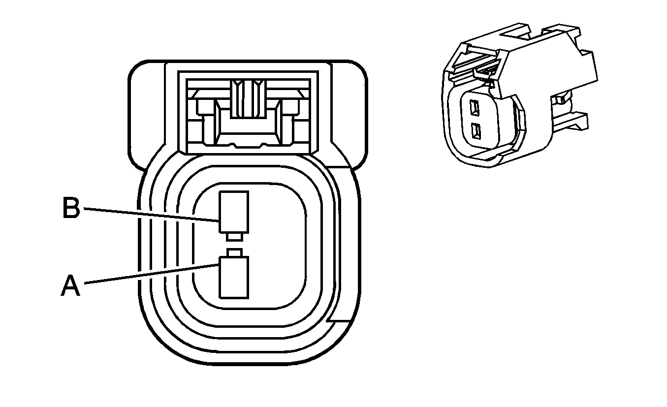
Pin | Wire Color | Circuit No. | Function | ||||
A | BK | 470 | Low Reference | ||||
B | D-GN | 890 | Fuel Tank Pressure Sensor Signal | ||||
C | GY | 474 | 5-Volt Reference | ||||
| |||||||
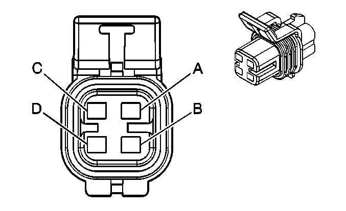
|---|---|---|---|---|---|---|---|
Connector Part Information |
| ||||||
Pin | Wire Color | Circuit No. | Function | ||||
A | TN | 1664 | HO2S Low Signal Bank 1 Sensor 1 | ||||
B | PU/WH | 1665 | HO2S High Signal Bank 1 Sensor 1 | ||||
C | BK/WH | 3113 | HO2S Heater Low Control Bank 1 Sensor 1 | ||||
D | PK | 539 | Ignition 1 Voltage | ||||
| |||||||
|---|---|---|---|---|---|---|---|
Connector Part Information |
| ||||||
Pin | Wire Color | Circuit No. | Function | ||||
A | TN | 1664 | HO2S Low Signal Bank 1 Sensor 1 | ||||
B | PU/WH | 1665 | HO2S High Signal Bank 1 Sensor 1 | ||||
C | -- | -- | Not Used | ||||
D | PK | 539 | Ignition 1 Voltage | ||||
E | BK/WH | 3113 | HO2S Heater Low Control Bank 1 Sensor 1 | ||||
|
| |||||||
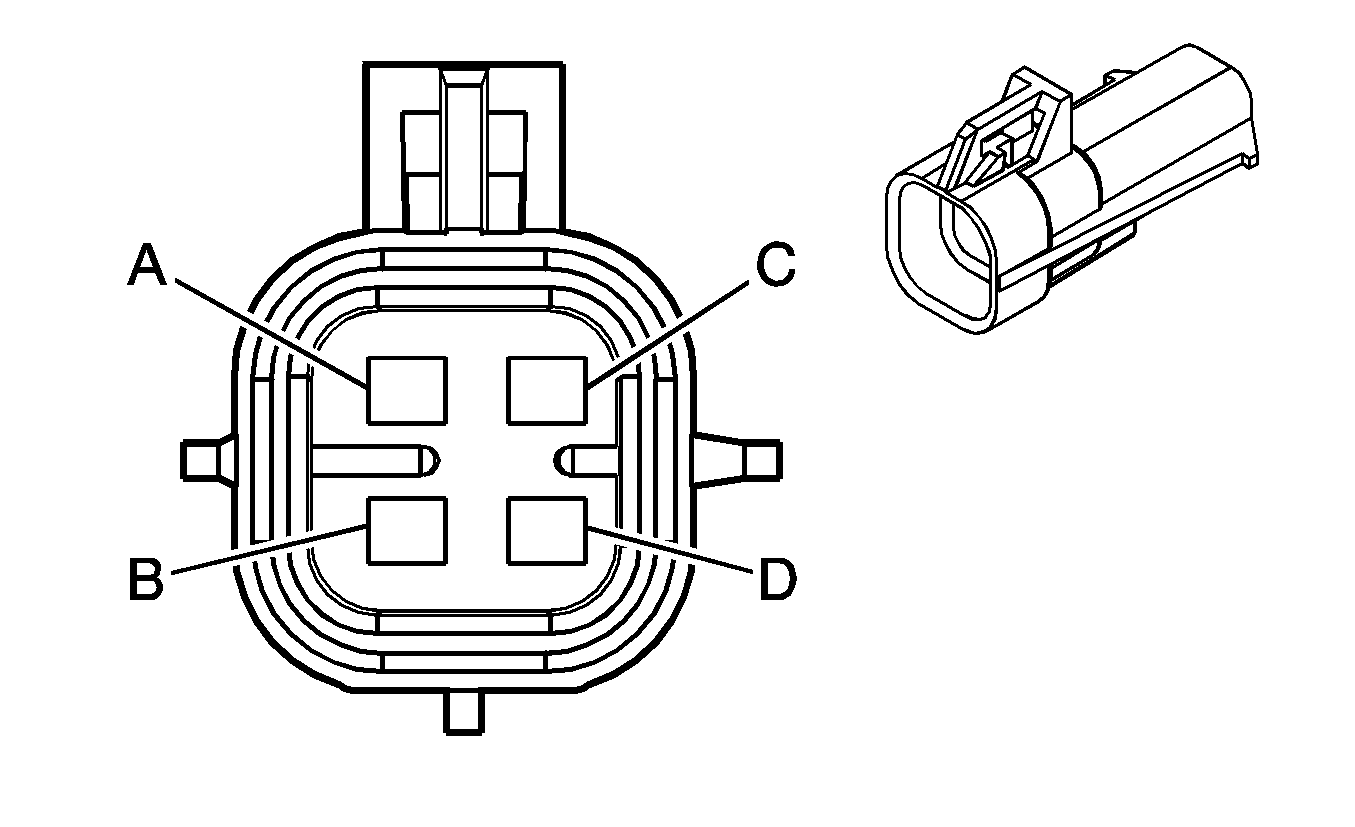
|---|---|---|---|---|---|---|---|
Connector Part Information |
| ||||||
Pin | Wire Color | Circuit No. | Function | ||||
A | TN/WH | 1669 | HO2S Low Signal Bank 1 Sensor 2 | ||||
B | PU/WH | 1668 | HO2S High Signal Bank 1 Sensor 2 | ||||
C | BN | 2391 | HO2S Heater Low Control Bank 1 Sensor 2 | ||||
D | PK | 1539 | Ignition 1 Voltage | ||||
|
| |||||||
|---|---|---|---|---|---|---|---|
Connector Part Information |
| ||||||
Pin | Wire Color | Circuit No. | Function | ||||
A | TN | 1667 | HO2S Low Signal Bank 2 Sensor 1 | ||||
B | PU | 1666 | HO2S High Signal Bank 2 Sensor 1 | ||||
C | L-GN | 3212 | HO2S Heater Low Control Bank 2 Sensor 1 | ||||
D | PK | 539 | HO2S High Signal Bank 2 Sensor 1 | ||||
|
| |||||||
|---|---|---|---|---|---|---|---|
Connector Part Information |
| ||||||
Pin | Wire Color | Circuit No. | Function | ||||
A | TN | 1667 | HO2S Low Signal Bank 2 Sensor 1 | ||||
B | PU | 1666 | HO2S High Signal Bank 2 Sensor 1 | ||||
C | -- | -- | Not Used | ||||
D | PK | 539 | HO2S High Signal Bank 2 Sensor 1 | ||||
E | L-GN | 3212 | HO2S Heater Low Control Bank 2 Sensor 1 | ||||
|
| |||||||
|---|---|---|---|---|---|---|---|
Connector Part Information |
| ||||||
Pin | Wire Color | Circuit No. | Function | ||||
A | TN | 1671 | HO2S Low Signal Bank 2 Sensor 2 | ||||
B | PU | 1670 | HO2S High Signal Bank 2 Sensor 2 | ||||
C | RD/WH | 3223 | HO2S Heater Low Control Bank 2 Sensor 2 | ||||
D | PK | 1539 | Ignition 1 Voltage | ||||
|
| |||||||
|---|---|---|---|---|---|---|---|
Connector Part Information |
| ||||||
Pin | Wire Color | Circuit No. | Function | ||||
A | TN | 1671 | HO2S Low Signal Bank 2 Sensor 2 | ||||
B | PU | 1670 | HO2S High Signal Bank 2 Sensor 2 | ||||
C | RD/WH | 3223 | HO2S Heater Low Control Bank 2 Sensor 2 | ||||
D | PK | 1539 | Ignition 1 Voltage | ||||
| |||||||
|---|---|---|---|---|---|---|---|
Connector Part Information |
| ||||||
Pin | Wire Color | Circuit No. | Function | ||||
A | BK | 550 | Ground | ||||
B | BN | 2129 | Low Reference | ||||
C | PU | 2121 | IC 1 Control | ||||
D | PK | 1039 | Ignition 1 Voltage | ||||
|
| |||||||
|---|---|---|---|---|---|---|---|
Connector Part Information |
| ||||||
Pin | Wire Color | Circuit No. | Function | ||||
A | BK | 550 | Ground | ||||
B | BN | 2130 | Low Reference | ||||
C | RD | 2122 | IC 2 Control | ||||
D | PK | 1239 | Ignition 1 Voltage | ||||
|
| |||||||
|---|---|---|---|---|---|---|---|
Connector Part Information |
| ||||||
Pin | Wire Color | Circuit No. | Function | ||||
A | BK | 550 | Ground | ||||
B | BN | 2129 | Low Reference | ||||
C | L-BU | 2123 | IC 3 Control | ||||
D | PK | 1039 | Ignition 1 Voltage | ||||
|
| |||||||
|---|---|---|---|---|---|---|---|
Connector Part Information |
| ||||||
Pin | Wire Color | Circuit No. | Function | ||||
A | BK | 550 | Ground | ||||
B | BN | 2130 | Low Reference | ||||
C | D-GN | 2124 | IC 4 Control | ||||
D | PK | 1239 | Ignition 1 Voltage | ||||
|
| |||||||
|---|---|---|---|---|---|---|---|
Connector Part Information |
| ||||||
Pin | Wire Color | Circuit No. | Function | ||||
A | BK | 550 | Ground | ||||
B | BN | 2129 | Low Reference | ||||
C | D-GN | 2125 | IC 5 Control | ||||
D | PK | 1039 | Ignition 1 Voltage | ||||
|
| |||||||
|---|---|---|---|---|---|---|---|
Connector Part Information |
| ||||||
Pin | Wire Color | Circuit No. | Function | ||||
A | BK | 550 | Ground | ||||
B | BN | 2130 | Low Reference | ||||
C | L-BU | 2126 | IC 6 Control | ||||
D | PK | 1239 | Ignition 1 Voltage | ||||
|
| |||||||
|---|---|---|---|---|---|---|---|
Connector Part Information |
| ||||||
Pin | Wire Color | Circuit No. | Function | ||||
A | BK | 550 | Ground | ||||
B | BN | 2129 | Low Reference | ||||
C | RD | 2127 | IC 7 Control | ||||
D | PK | 1039 | Ignition 1 Voltage | ||||
|
| |||||||
|---|---|---|---|---|---|---|---|
Connector Part Information |
| ||||||
Pin | Wire Color | Circuit No. | Function | ||||
A | BK | 550 | Ground | ||||
B | BN | 2130 | Low Reference | ||||
C | PU | 2128 | IC 8 Control | ||||
D | PK | 1239 | Ignition 1 Voltage | ||||
| |||||||
|---|---|---|---|---|---|---|---|
Connector Part Information |
| ||||||
Pin | Wire Color | Circuit No. | Function | ||||
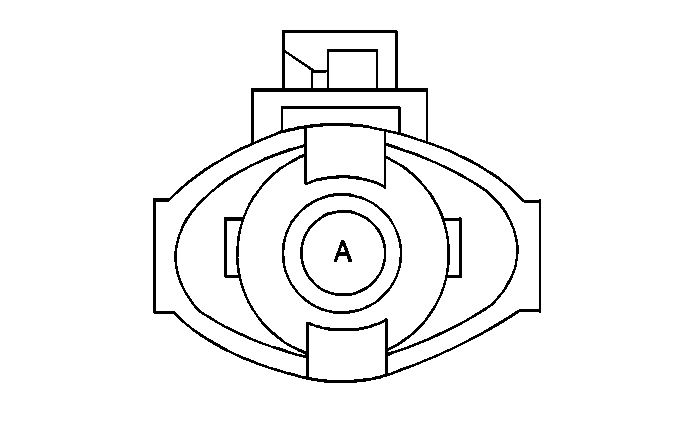
A | D-BU | 496 | Knock Sensor 1 Signal | ||||
|
| |||||||
|---|---|---|---|---|---|---|---|
Connector Part Information |
| ||||||
Pin | Wire Color | Circuit No. | Function | ||||
A | L-BU | 1876 | Knock Sensor 2 Signal | ||||
| |||||||
|---|---|---|---|---|---|---|---|
Connector Part Information |
| ||||||
Pin | Wire Color | Circuit No. | Function | ||||
A | OG/BK | 469 | Low Reference | ||||
B | L-GN | 432 | MAP Sensor Signal | ||||
C | GY | 597 | 5-Volt Reference | ||||
| |||||||
|---|---|---|---|---|---|---|---|
Connector Part Information |
| ||||||
Pin | Wire Color | Circuit No. | Function | ||||
A | BK | 552 | Low Reference | ||||
B | TN | 472 | IAT Sensor Signal | ||||
C | BK/WH | 451 | Ground | ||||
D | PK | 439 | Ignition 1 Voltage | ||||
E | YE | 492 | MAF Sensor Signal | ||||
| |||||||
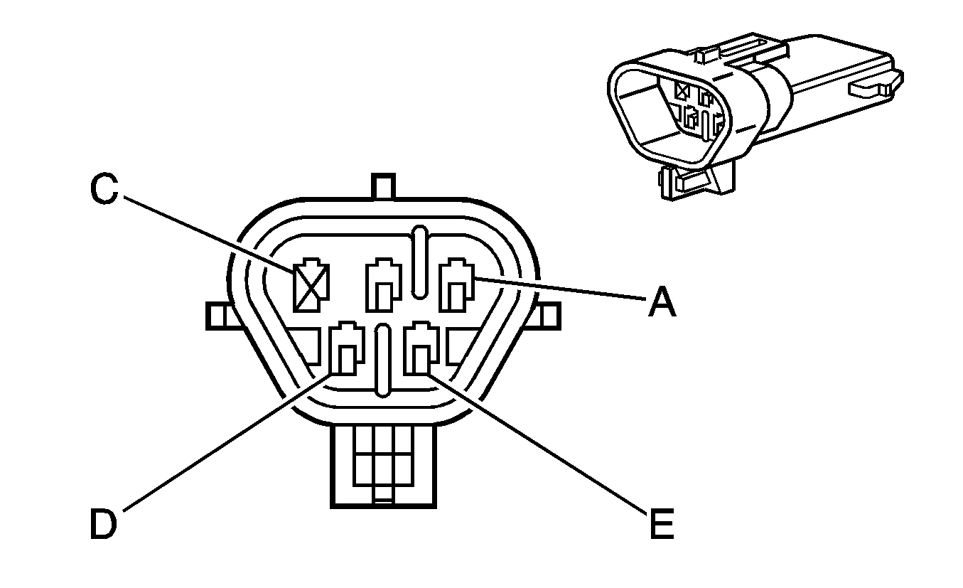
|---|---|---|---|---|---|---|---|
Connector Part Information |
| ||||||
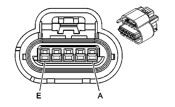
Pin | Wire Color | Circuit No. | Function | ||||
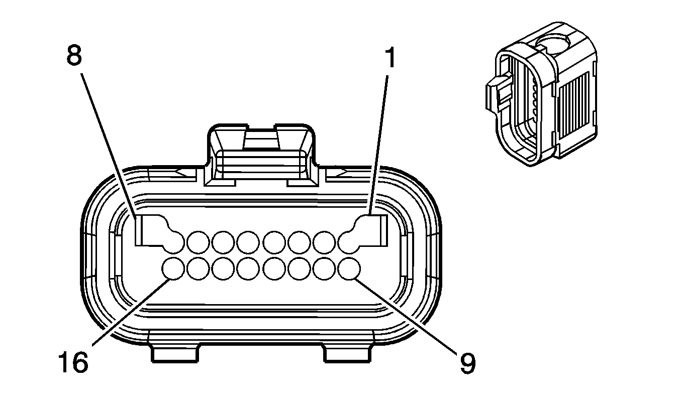
1 | D-GN | 485 | TP Sensor 1 Signal | ||||
2 | GY | 416 | 5-Volt Reference | ||||
3 | BK | 452 | Low Reference | ||||
4 | D-BU | 84 | Cruise Control Set/Coast Switch Signal | ||||
5 | GY/BK | 87 | Cruise Control Resume/Accel Switch Signal | ||||
6 | L-BU | 1320 | CHMSL Supply Voltage | ||||
7 | PK | 1339 | Ignition 1 Voltage | ||||
8 | BN | 582 | TAC Motor Control - 2 | ||||
9 | L-BU/BK | 1688 | 5-Volt Reference | ||||
10 | BK/WH | 1704 | Low Reference | ||||
11 | PU | 486 | TP Sensor 2 Signal | ||||
12 | OG/BK | 1061 | UART Serial Data | ||||
13 | D-BU/WH | 774 | UART Serial Data | ||||
14 | GY | 397 | Cruise Control On Switch Signal | ||||
15 | BK | 550 | Ground | ||||
16 | YE | 581 | TAC Motor Control - 1 | ||||
| |||||||
|---|---|---|---|---|---|---|---|
Connector Part Information |
| ||||||
Pin | Wire Color | Circuit No. | Function | ||||
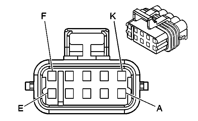
A | -- | -- | Not Used | ||||
B | PU | 1272 | 5-Volt Reference | ||||
C | L-BU | 1162 | APP Sensor 2 Signal | ||||
D | TN | 1274 | Low Reference | ||||
E | -- | -- | Not Used | ||||
F | D-BU | 1161 | APP Sensor 1 Signal | ||||
G | WH/BK | 1164 | 5-Volt Reference | ||||
H | Not Used | ||||||
J | BN | 1271 | Low Reference | ||||
K | -- | -- | Not Used | ||||
| |||||||
|---|---|---|---|---|---|---|---|
Connector Part Information |
| ||||||
Pin | Wire Color | Circuit No. | Function | ||||
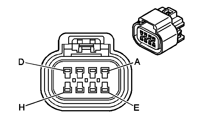
A | YE | 581 | TAC Motor Control - 1 | ||||
B | BK/WH | 1704 | Low Reference | ||||
C | BN | 582 | TAC Motor Control - 2 | ||||
D | BK | 452 | Low Reference | ||||
E | L-BU/BK | 1688 | 5-Volt Reference | ||||
F | PU | 486 | TP Sensor 2 Signal | ||||
G | D-GN | 485 | TP Sensor 1 Signal | ||||
H | GY | 416 | 5-Volt Reference | ||||
