HVAC Module Assembly Replacement Non-HP2
Special Tools
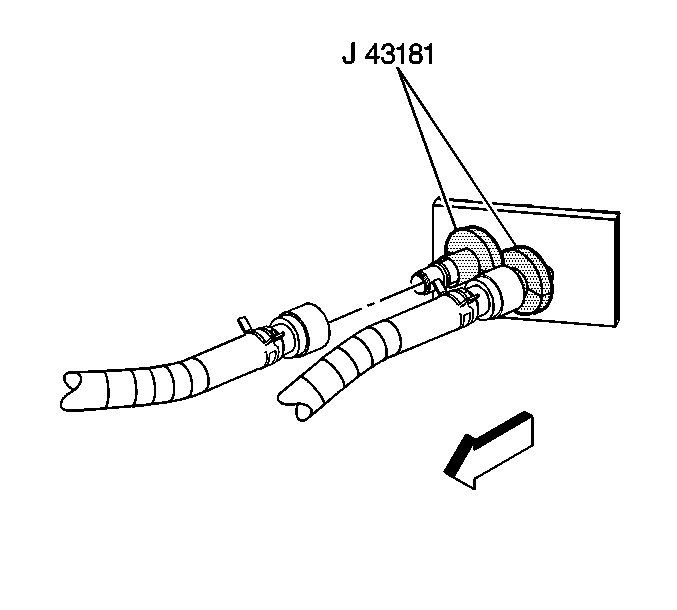
J 43181 Heater Line QC Release Tool
Removal Procedure
- Drain the engine coolant. Refer to
Cooling System Draining and Filling.

- Using the
J 43181 disconnect the inlet heater hose from the heater core.
| 2.1. | Install the
J 43181 to the heater core pipe. |
| 2.2. | Close the tool around the heater core pipe. |
| 2.3. | Firmly pull the tool into the quick connect end of the heater hose. |
| 2.4. | Firmly grasp the heater hose. Pull the heater hose forward in order to disengage the inlet hose from the heater core. |
- Using the
J 43181 disconnect the surge tank outlet hose from the heater core.
| 3.1. | Install the
J 43181 to the heater core pipe. |
| 3.2. | Close the tool around the heater core pipe. |
| 3.3. | Firmly pull the tool into the quick connect end of the heater hose. |
| 3.4. | Firmly grasp the heater hose. Pull the heater hose forward in order to disengage the surge tank outlet hose from the heater core. |
- Remove the upper intake manifold sight shield. Refer to
Upper Intake Manifold Sight Shield Replacement.
- Remove the battery. Refer to
Battery Replacement.
- Remove the accumulator. Refer to
Air Conditioning Accumulator Replacement.
- Remove the instrument panel to the service position. Refer to
Instrument Panel Service Positioning.
- Remove the HVAC module drain hose.
- Disconnect the electrical harnesses and the ground connections from the HVAC module.

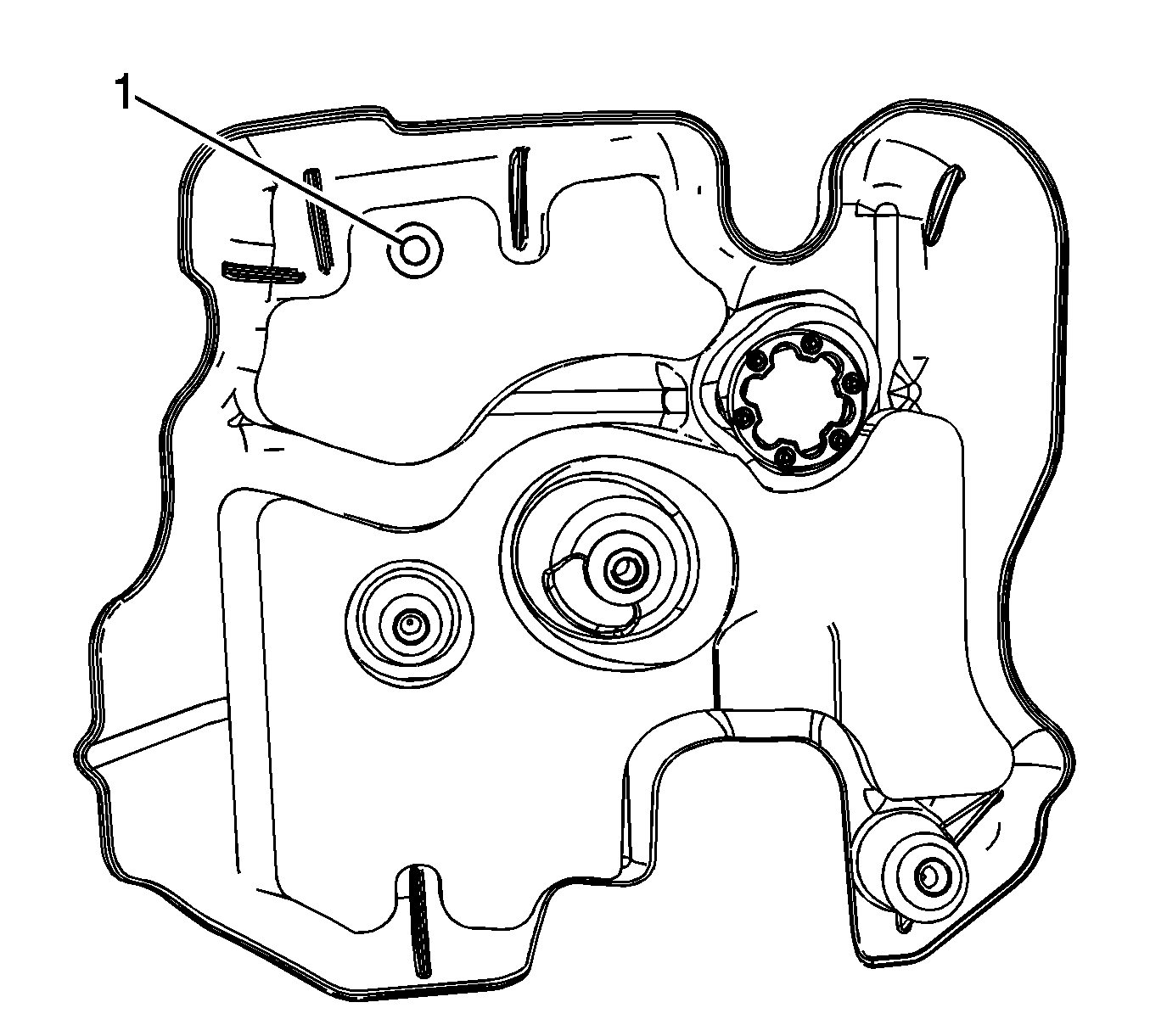
Note: Ensure that any wiring harness does not interfere with the drilling process of the rear engine cover.
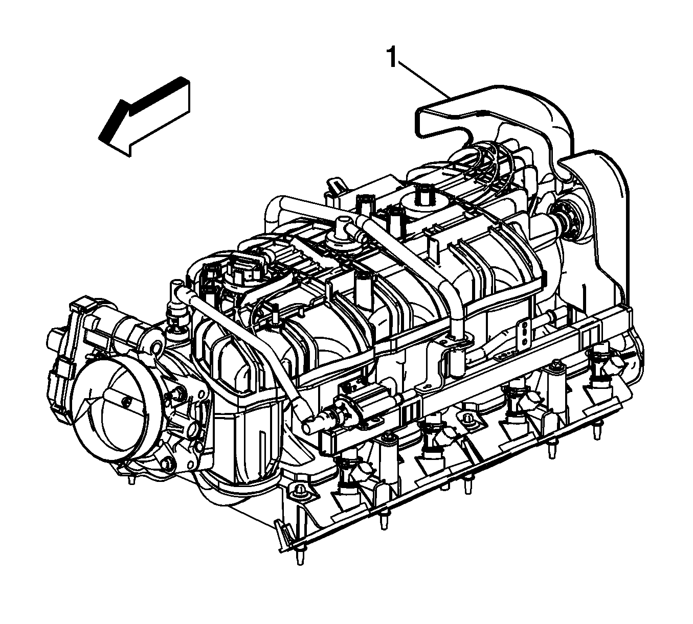
- Locate the rear engine cover (1) on rear of intake manifold.

- Reposition the acoustic foam (if applicable) down from the access location (1).
Note: Drill an 25.4 mm (1 in.) diameter hole in the rear engine cover (1) to access the HVAC module retaining nut located behind rear engine cover.

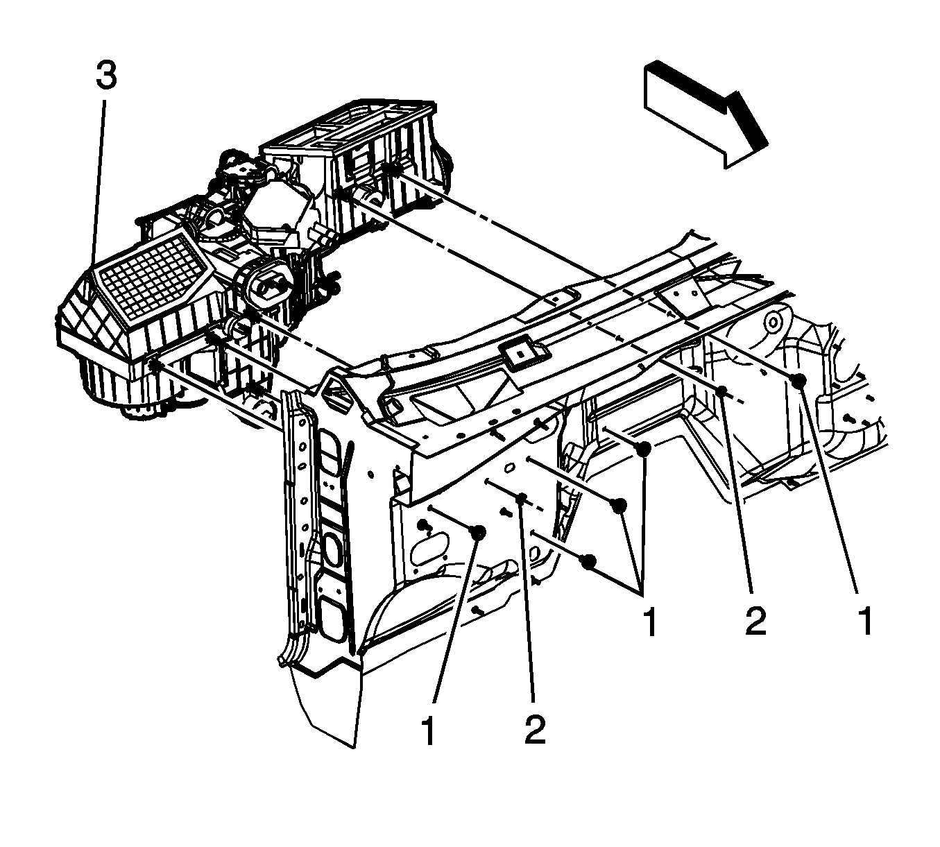
- Remove the nuts (2) from the HVAC module (3).
- Remove the bolts (1) from the HVAC module (3).
- Remove the HVAC module (3).
Installation Procedure

- If replacing the HVAC module, transfer the components from the old HVAC module as necessary.
- Install the HVAC module (3).
Caution: Refer to Fastener Caution in the Preface section.
- Install the nuts (2) to the HVAC module (3) and tighten to
9 N·m (80 lb in).
- Install the bolts (1) to the HVAC module (3) and tighten to
4 N·m (35 lb in).
- Reposition acoustic foam (if applicable) to original position or cover access hole with equivalent foam tape (1).
- Connect the electrical harness and the ground connections.
- Install the HVAC module drain hose.
- Install the instrument panel. Refer to
Instrument Panel Service Positioning.
- Install the upper intake manifold sight shield. Refer to
Upper Intake Manifold Sight Shield Replacement.
- Install the battery. Refer to
Battery Replacement.
- Install the accumulator. Refer to
Air Conditioning Accumulator Replacement.

- Install the surge tank outlet hose to the heater core.
Firmly push the quick connect onto the heater core pipe until you hear an audible click.
- Install the inlet heater hose to the heater core.
Firmly push the quick connect onto the heater core pipe until you hear an audible click.
- Fill the engine coolant. Refer to
Cooling System Draining and Filling.
HVAC Module Assembly Replacement HP2
Special Tools
J 43181 Heater Line QC Release Tool
Removal Procedure
- Drain the engine coolant. Refer to
Cooling System Draining and Filling.

- Using the
J 43181 disconnect the inlet heater hose from the heater core.
| 2.1. | Install the
J 43181 to the heater core pipe. |
| 2.2. | Close the tool around the heater core pipe. |
| 2.3. | Firmly pull the tool into the quick connect end of the heater hose. |
| 2.4. | Firmly grasp the heater hose. Pull the heater hose forward in order to disengage the inlet hose from the heater core. |
- Using the
J 43181 disconnect the surge tank outlet hose from the heater core.
| 3.1. | Install the
J 43181 to the heater core pipe. |
| 3.2. | Close the tool around the heater core pipe. |
| 3.3. | Firmly pull the tool into the quick connect end of the heater hose. |
| 3.4. | Firmly grasp the heater hose. Pull the heater hose forward in order to disengage the surge tank outlet hose from the heater core. |
- Remove the upper intake manifold sight shield. Refer to
Upper Intake Manifold Sight Shield Replacement.
- Remove the drive motor generator control module assembly. Refer to
Drive Motor Generator Control Module Assembly Replacement.
- Remove the battery. Refer to
Battery Replacement.
- Remove the accumulator. Refer to
Air Conditioning Accumulator Replacement.
- Remove the instrument panel to the service position. Refer to
Instrument Panel Service Positioning.
- Remove the HVAC module drain hose.
- Disconnect the electrical harnesses and the ground connections from the HVAC module.

- Locate the rear engine cover (1) on rear of intake manifold.
Note: Ensure that any wiring harness does not interfere with the drilling process of the rear engine cover.

- Reposition the acoustic foam (if applicable) down from the access location (1).
Note: Drill an 25.4 mm (1 in.) diameter hole in the rear engine cover (1) to access the HVAC module retaining nut located behind rear engine cover.

- Remove the nuts (2) from the HVAC module (3).
- Remove the bolts (1) from the HVAC module (3).
- Remove the HVAC module (3).
Installation Procedure

- If replacing the HVAC module, transfer the components from the old HVAC module as necessary.
- Install the HVAC module (3).
Caution: Refer to Fastener Caution in the Preface section.
- Install the nuts (2) to the HVAC module (3) and tighten to
9 N·m (80 lb in).
- Install the bolts (1) to the HVAC module (3) and tighten to
4 N·m (35 lb in).
- Reposition acoustic foam (if applicable) to original position or cover access hole with equivalent foam tape (1).
- Connect the electrical harness and the ground connections.
- Install the HVAC module drain hose.
- Install the instrument panel. Refer to
Instrument Panel Service Positioning.
- Install the upper intake manifold sight shield. Refer to
Upper Intake Manifold Sight Shield Replacement.
- Install the drive motor generator control module assembly. Refer to
Drive Motor Generator Control Module Assembly Replacement.
- Install the battery. Refer to
Battery Replacement.
- Install the accumulator. Refer to
Air Conditioning Accumulator Replacement.

- Install the surge tank outlet hose to the heater core.
Firmly push the quick connect onto the heater core pipe until you hear an audible click.
- Install the inlet heater hose to the heater core.
Firmly push the quick connect onto the heater core pipe until you hear an audible click.
- Fill the engine coolant. Refer to
Cooling System Draining and Filling.


