Pinion Depth Adjustment RPO (M41)
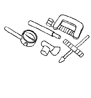
Tools Required
Setting Pinion Depth
Pinion Depth (the distance from the face of the pinion gear to the center
line of the ring gear) is critical to all differentials. Each ring
and pinion gear set is matched so as to produce the best tooth
contact pattern. This relationship (pinion depth) is controlled
by placing the proper selective shim between the pinion
gear and the inner bearing. If the original ring, pinion
gears and pinion bearings are reused, the original ring
size selective shim will set the proper pinion depth. Pinion
depth is set with a Pinion Setting Gage Set which provides
a nominal or zero as a gaging reference to find the pinion
center.
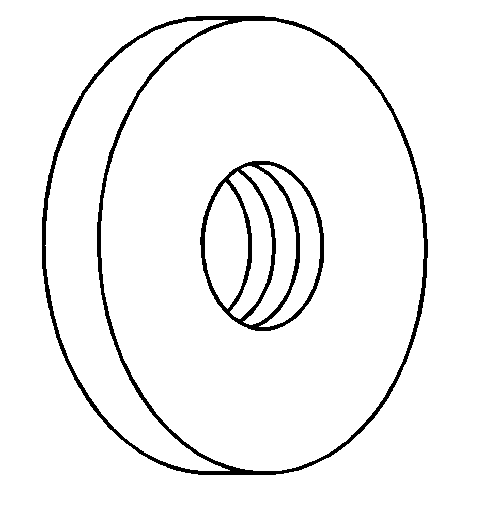
- Lubricate both inner and outer pinion bearings with wheel bearing
lubricant GM P/N 1051344 (Canadian P/N 993037),
or equivalent.

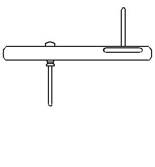
- Assemble the gauge block
and stud.
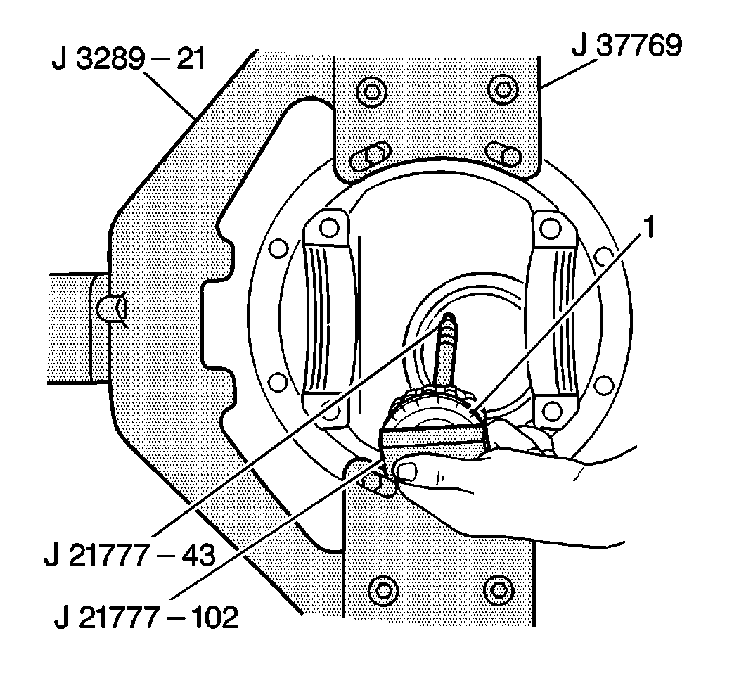
- Place the inner pinion
bearing into the differential carrier and install a J 21777-102
with the Differential Dummy attachment,
aJ 23597-12
,
a J 21777-43
and
a J 21777-42
.
Notice: Use the correct fastener in the correct location. Replacement fasteners
must be the correct part number for that application. Fasteners requiring
replacement or fasteners requiring the use of thread locking compound or sealant
are identified in the service procedure. Do not use paints, lubricants, or
corrosion inhibitors on fasteners or fastener joint surfaces unless specified.
These coatings affect fastener torque and joint clamping force and may damage
the fastener. Use the correct tightening sequence and specifications when
installing fasteners in order to avoid damage to parts and systems.
- Hold the J 21777-43
stationary
and tighten the jam nut.
Tighten
Tighten the jam nut to 2 N·m (18 lb in).
- Rotate the J 21777-102
25 revolutions with the differential dummy attachment to ensure the
pinion bearings are fully seated.
- Retighten the jam nut.
Tighten
Tighten the jam nut to 2 N·m (18 lb in).
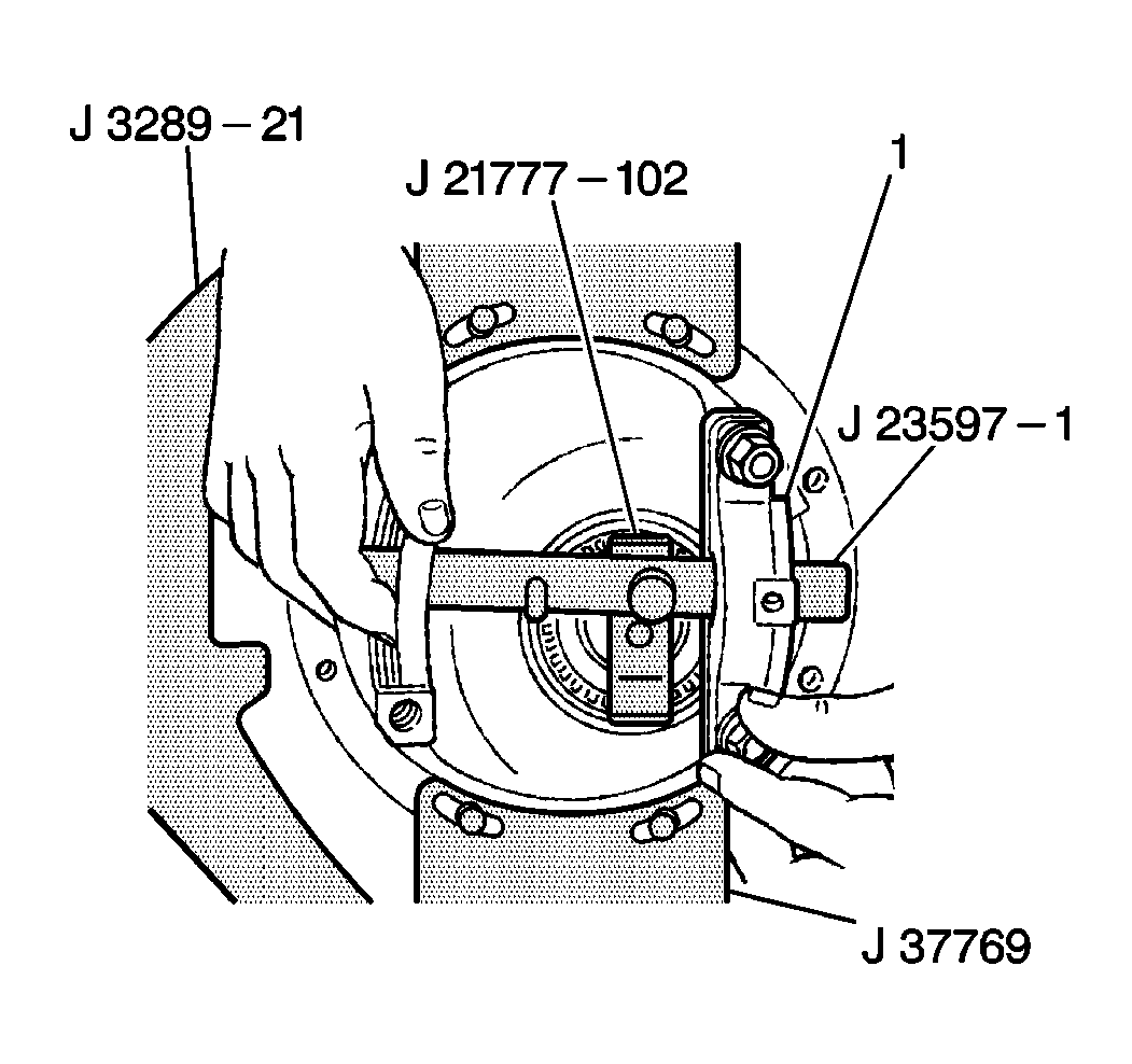
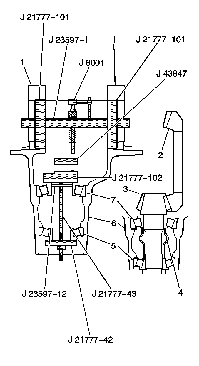
- Install the J 21777-101
in the side bearing bores with J 23597-1
through both side bearing
discs.
- Rotate the J 21777-102
with the differential dummy attachment until both gauging levels are
parallel with the J 21777-101
.

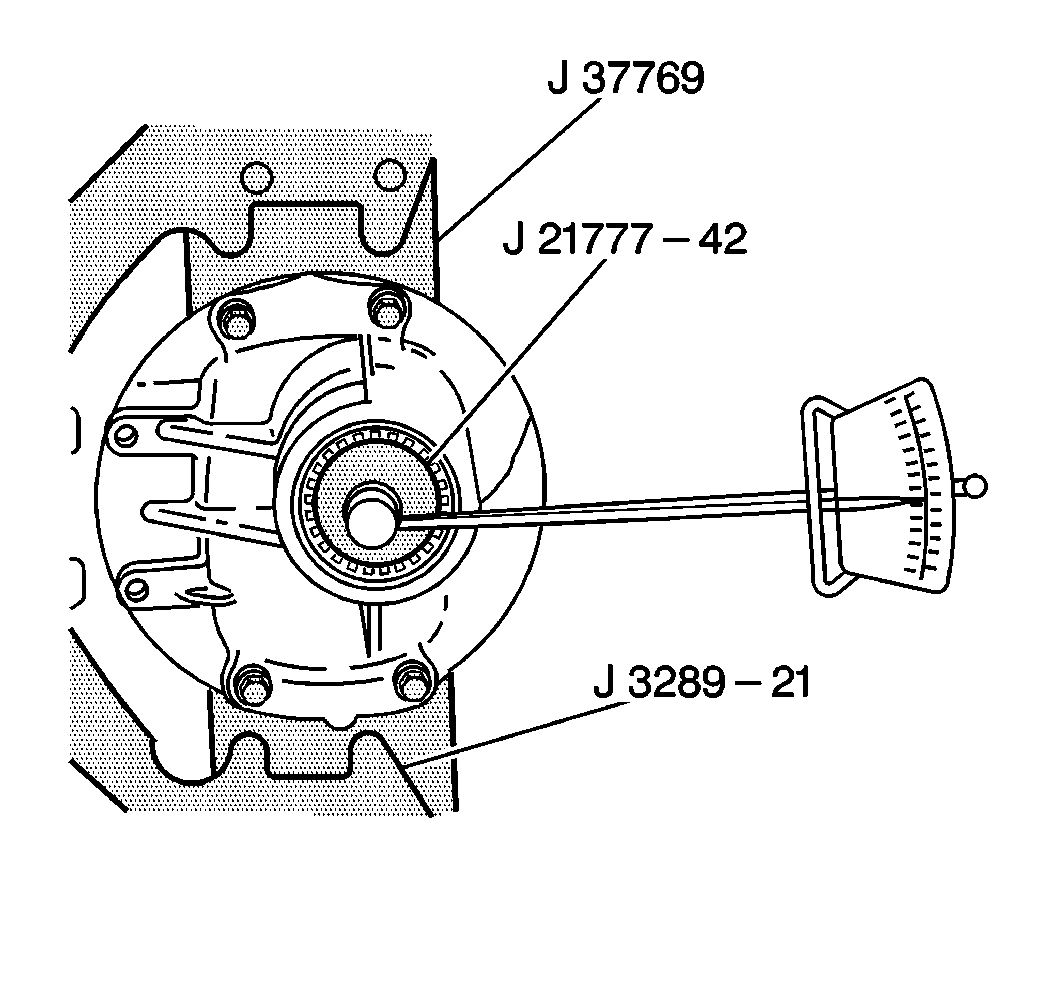
- Install the dial indicator
spring loaded plunger extension through the J 23597-1
and position over the 97 mm level of the J 21777-102
with the differential dummy attachment.

- Install a J 8001
to the J 23597-1
.
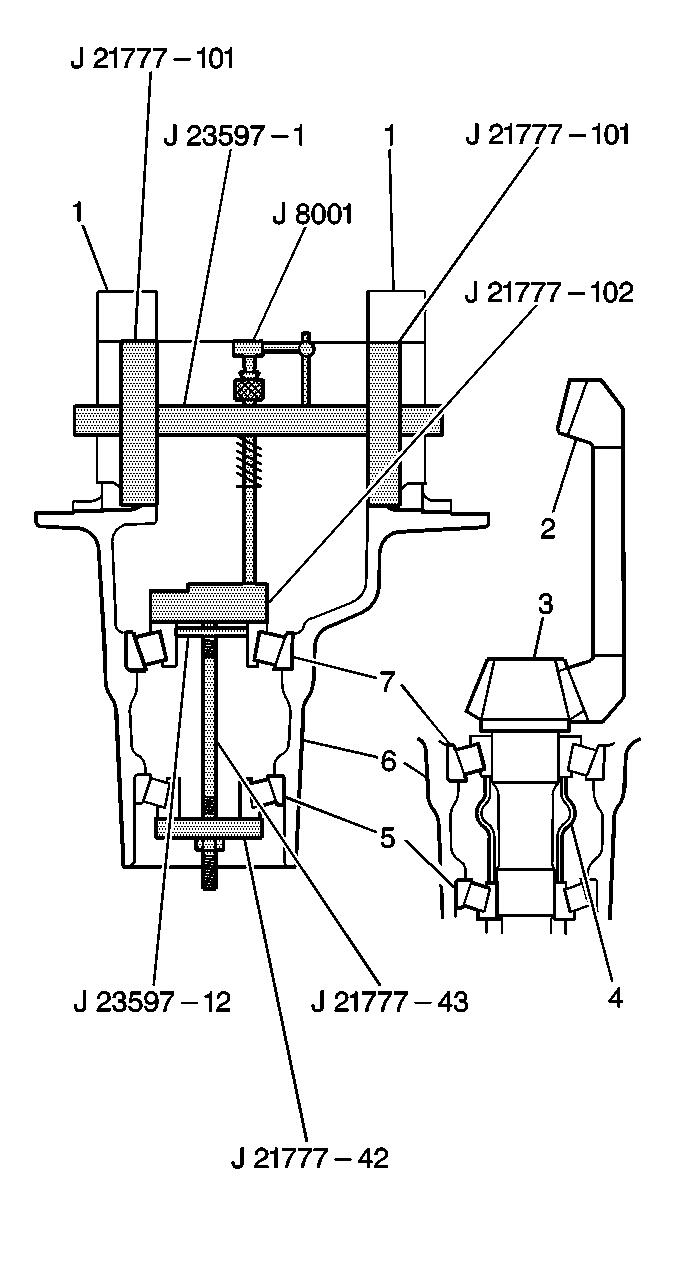
- Position the gauge plunger
over the plunger extension and slightly load the indicator.
- Rotate the J 8001
adjustable face so that the 0 is aligned with the dial indicator needle.
- Slowly rotate the J 23597-1
back and forth so that the spring loaded plunger extension
sweeps back and forth across the 97 mm level of the J 21777-102
while observing the dial indicator.
- Stop the J 23597-1
at the dial indicator's greatest point of deflection.
- Without disturbing the J 8001
needle setting, rotate the J 8001
adjustable face so that 0 is aligned with the dial indicator
needle.
- Slowly rotate the J 23597-1
one way until the spring loaded plunger extension is no longer
making contact with the J 21777-102
.
- Record the deflection reading on the J 8001
.
- This reading indicates the selective shim size required for the
correct pinion depth. Refer to
Spacer and Shim Specifications
for the appropriate shim.
- Remove the J 8001
and spring loaded plunger extension from the J 23597-1
.
- Remove the J 23597-1
and the 2 J 21777-101
from the differential carrier (6).
- Remove the J 21777-102
and with the J 23597-12
, the J 21777-43
and
the J 21777-42
from the
differential carrier.
- Remove both inner and outer pinion bearings from the differential
carrier (6).
Pinion Depth Adjustment RPO (M59)
Tools Required
| • | J 43847 Differential
Dummy Attachment |
Setting Pinion Depth
Pinion Depth (the distance from the face of the pinion gear to the center
line of the ring gear) is critical to all differentials. Each ring
and pinion gear set is matched so as to produce the best tooth
contact pattern. This relationship (pinion depth) is controlled
by placing the proper selective shim between the pinion
gear and the inner bearing. If the original ring, pinion
gears and pinion bearings are reused, the original ring size
selective shim will set the proper pinion depth. Pinion depth
is set with a Pinion Setting Gage Set which provides a nominal
or zero as a gaging reference to find the pinion center.
- Lubricate both inner and
outer pinion bearings (1) with wheel bearing lubricant GM P/N 1051344
(Canadian P/N 993037), or equivalent.
- Assemble the gage block and stud.
- Place the inner pinion
bearing into the differential carrier and install a J 21777-102
with the Differential Dummy attachment,
aJ 23597-12
,
a J 21777-43
and
a J 21777-42
.
Notice: Use the correct fastener in the correct location. Replacement fasteners
must be the correct part number for that application. Fasteners requiring
replacement or fasteners requiring the use of thread locking compound or sealant
are identified in the service procedure. Do not use paints, lubricants, or
corrosion inhibitors on fasteners or fastener joint surfaces unless specified.
These coatings affect fastener torque and joint clamping force and may damage
the fastener. Use the correct tightening sequence and specifications when
installing fasteners in order to avoid damage to parts and systems.
- Hold the J 21777-43
stationary
and tighten the jam nut.
Tighten
Tighten the jam nut to 2 N·m (18 lb in).
- Rotate the J 21777-102
25 revolutions with the differential dummy attachment to ensure the
pinion bearings are fully seated.
- Retighten the jam nut.
Tighten
Tighten the jam nut to 2 N·m (18 lb in).
- Install the J 21777-101
in the side bearing bores with J 23597-1
through both side bearing
discs.
- Rotate the J 21777-102
with the differential dummy attachment until both gaging levels are
parallel with the J 21777-101
.
- Install the dial indicator
spring loaded plunger extension through the J 23597-1
and position over the 97 mm level of the J 21777-102
with the differential dummy attachment.
- Install a J 8001
to the J 23597-1
.
- Position the gauge plunger
over the plunger extension and slightly load the indicator.
- Rotate the J 8001
adjustable face so that the 0 is aligned with the dial indicator needle.
- Slowly rotate the J 23597-1
back and forth so that the spring loaded plunger extension
sweeps back and forth across the 97 mm level of the J 21777-102
with the J 43847
while observing the dial indicator.
- Stop the J 23597-1
at the dial indicator's greatest point of deflection.
- Without disturbing the J 8001
needle setting, rotate the J 8001
adjustable face so that 0 is aligned with the dial indicator
needle.
- Slowly rotate the J 23597-1
one way until the spring loaded plunger extension is no longer
making contact with the J 21777-102
.
- Record the deflection reading on the J 8001
.
- This reading indicates the selective shim size required for the
correct pinion depth. Refer to
Spacer and Shim Specifications
for the appropriate shim.
- Remove the J 8001
and spring loaded plunger extension from the J 23597-1
.
- Remove the J 23597-1
and the 2 J 21777-101
from the differential carrier (6).
- Remove the J 21777-102
and the differential dummy attachment, with the J 23597-12
, the J 21777-43
and the J 21777-42
from the differential carrier.
- Remove both inner and outer pinion bearings from the differential
carrier (6).
