Power Vacuum Brake Booster Replacement 2.0L Non-ABS
Tools Required
| • | J 39567 Brake Booster Piston Rod Height Gage |
| • | J 37767 Brake Booster Piston Rod Adjuster |
Removal Procedure
Notice: Refer to Non-Serviceable Booster Notice in the Preface section.
- Remove the master cylinder assembly. Refer to Master Cylinder Replacement .
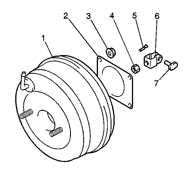
- Disconnect the brake vacuum hose from the brake booster (1).
- Remove the clevis pin (7) from the push rod clevis (6).
- Disconnect the push rod clevis from the brake pedal arm.
- Remove the nuts from the booster.
- Remove the booster.
Adjustment Procedure
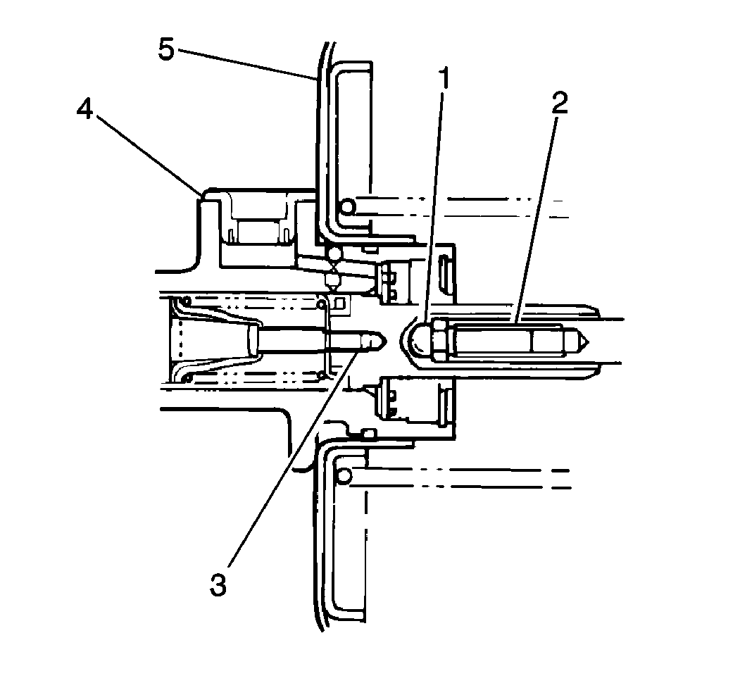
- Push the piston rod (2) several times, ensuring that the reaction disc is in place.
- Maintain atmospheric pressure inside the booster when measuring the clearance.
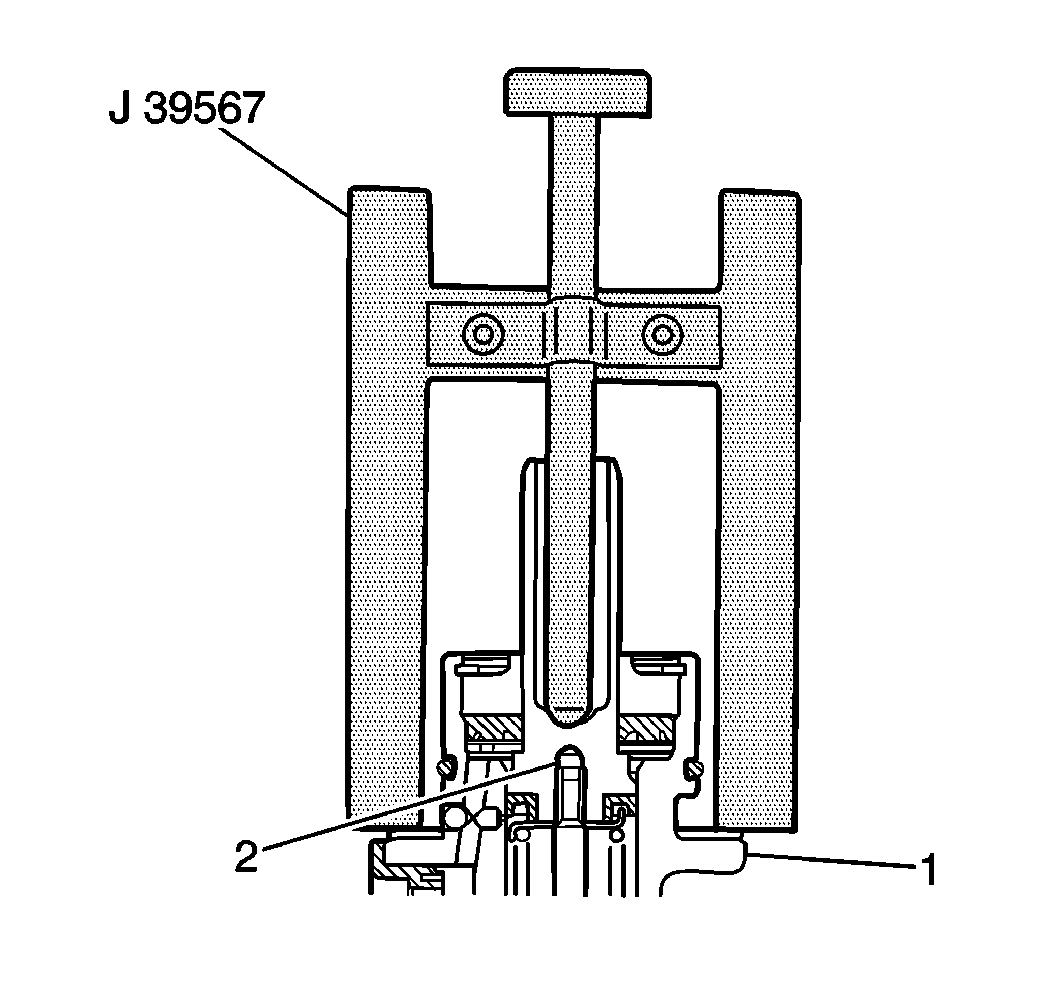
- Place the J 39567 on the master cylinder (1).
- Push the J 39567 pin down until it touches the master cylinder piston (2).
- Remove the J 39567 from the master cylinder.
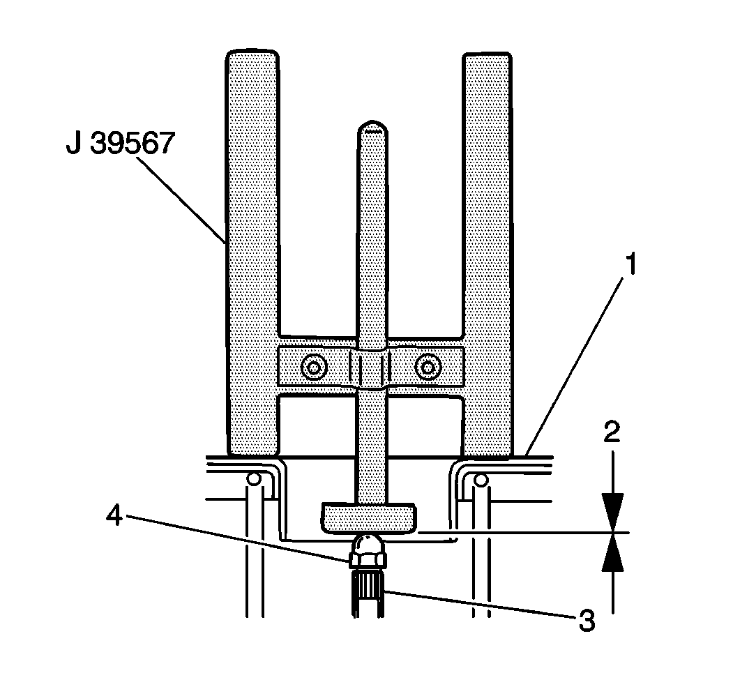
- Turn the J 39567 upside down and set it on the booster assembly (1).
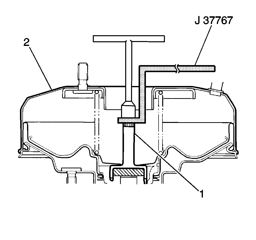
- If the measurement does not equal the specification, use the J 37767 in order to hold the booster piston rod (1).
- Turn the adjusting screw of the piston rod in order to adjust the clearance.
Specification
The clearance (2) between the booster piston rod (3) and the J 39567
should be 0 mm (0 in).
Installation Procedure
- Apply Wheel Bearing Lubricant, GM P/N 1051344 (Canadian P/N 993037), or the equivalent, to the master cylinder piston (3).
- Install the booster to the bulkhead.
- Install the 4 nuts (2).
- Connect the booster push rod clevis (6) to the brake pedal lever. Secure the clevis with the clevis pin and the clip.
- Install the push rod clevis (3).
- Tighten the clevis nut (2).
- Tighten the booster nuts (2).
- Connect the brake vacuum hose to the brake booster. Secure the hose with the hose clamp.
- Install the master cylinder. Refer to Master Cylinder Replacement .

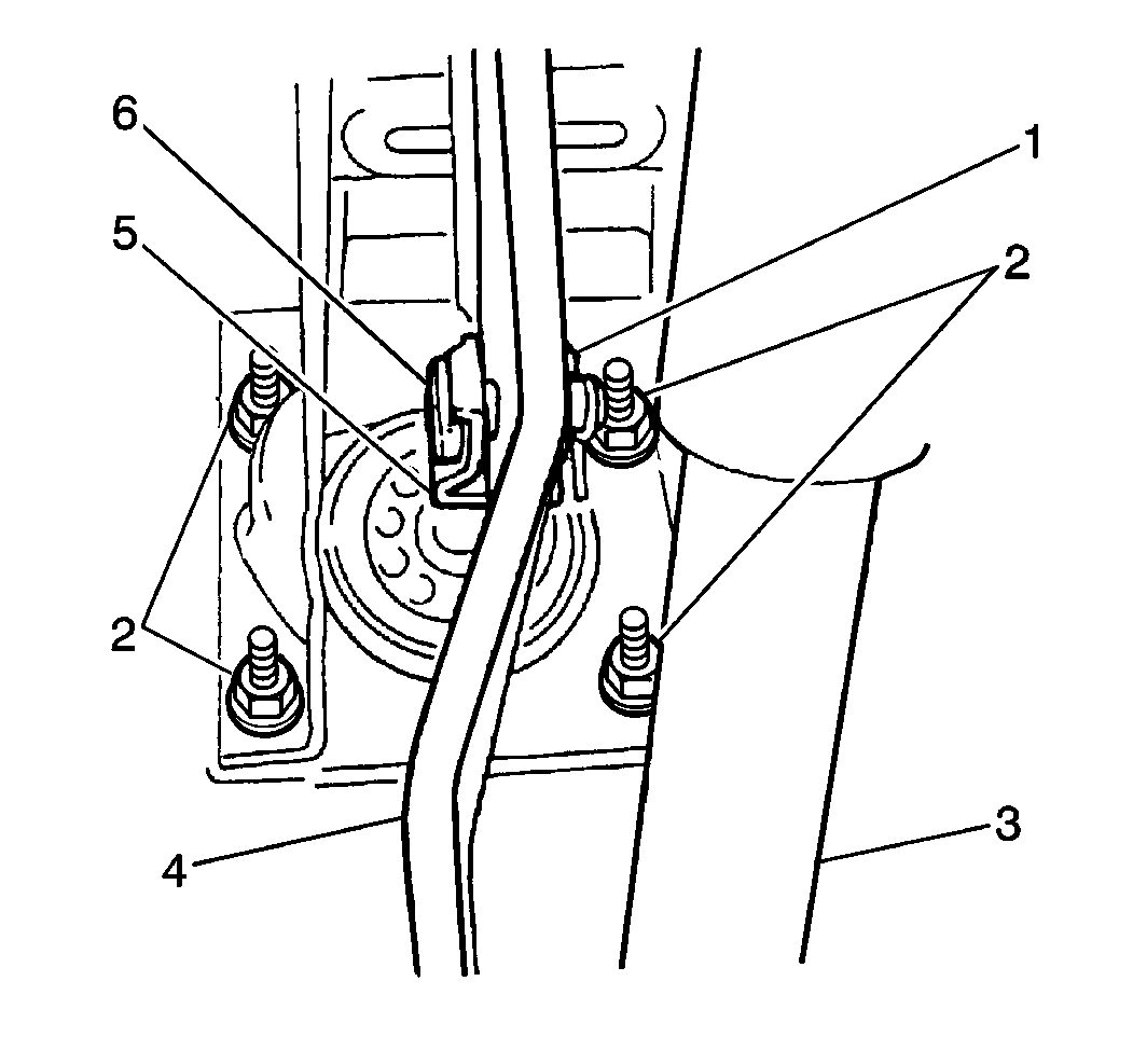
Important: DO NOT tighten the nuts on the bulkhead before the clevis nut.
Measurement
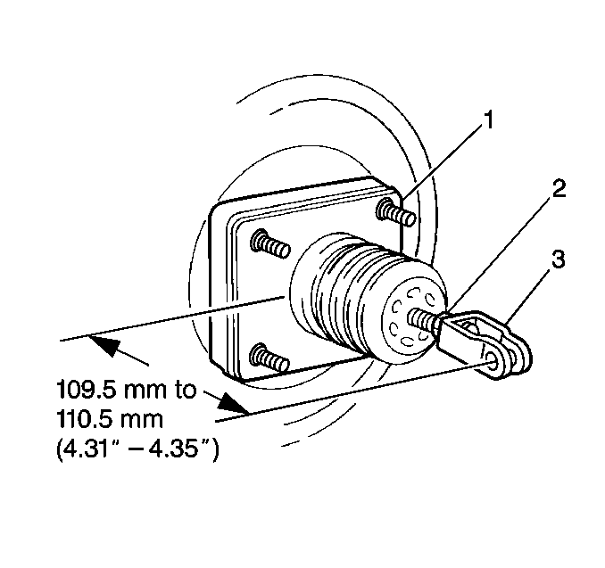
The distance between the clevis pin hole and the brake booster assembly should
be 109.5-110.5 mm (4.31-4.35 in).
Notice: Refer to Fastener Notice in the Preface section.
Tighten
Tighten the clevis nut to 25 N·m (18.4 lb ft).

Tighten
Tighten the nuts to 13 N·m (115.1 lb in).
Power Vacuum Brake Booster Replacement ABS
Tools Required
| • | J 39567 Brake Booster Piston Rod Height Gage |
| • | J 37767 Brake Booster Piston Rod Adjuster |
Removal Procedure
Notice: Refer to Non-Serviceable Booster Notice in the Preface section.
- Remove the Brake Pressure Modulator Valve from the vehicle. Refer to Brake Pressure Modulator Valve Replacement in Antilock Brake System.
- Remove the master cylinder assembly. Refer to Master Cylinder Replacement .
- Disconnect the brake vacuum hose from the brake booster (1).
- Remove the clevis pin (7) from the push rod clevis (6).
- Disconnect the push rod clevis from the brake pedal arm.
- Remove the nuts from the booster.
- Remove the booster.

Adjustment Procedure
- Push the piston rod (2) several times, ensuring that the reaction disc is in place.
- Maintain atmospheric pressure inside the booster when measuring the clearance.
- Place the J 39567 on the master cylinder (1).
- Push the J 39567 pin down until it touches the master cylinder piston (2).
- Remove the J 39567 from the master cylinder.
- Turn the J 39567 upside down and set it on the booster assembly (1).
- If the measurement does not equal the specification, use the J 37767 in order to hold the booster piston rod (1).
- Turn the adjusting screw of the piston rod in order to adjust the clearance.


Specification
The clearance (2) between the booster piston rod (3) and the J 39567
should be 0 mm (0 in).

Installation Procedure
- Apply Wheel Bearing Lubricant, GM P/N 1051344 (Canadian P/N 993037), or the equivalent, to the master cylinder piston (3).
- Install the booster to the bulkhead.
- Install the 4 nuts (2).
- Connect the booster push rod clevis (6) to the brake pedal lever. Secure the clevis with the clevis pin and the clip.
- Install the push rod clevis (3).
- Tighten the clevis nut (2).
- Tighten the booster nuts (2).
- Connect the brake vacuum hose to the brake booster. Secure the hose with the hose clamp.
- Install the master cylinder. Refer to Master Cylinder Replacement .
- Install the Brake Pressure Modulator Valve. Refer to Brake Pressure Modulator Valve Replacement in Antilock Brake System.


Important: DO NOT tighten the nuts on the bulkhead before the clevis nut.

Measurement
The distance between the clevis pin hole and the brake booster assembly should
be 109.5-110.5 mm (4.31-4.35 in).
Notice: Refer to Fastener Notice in the Preface section.
Tighten
Tighten the clevis nut to 25 N·m (18.4 lb ft).

Tighten
Tighten the nuts to 13 N·m (115.1 lb in).
