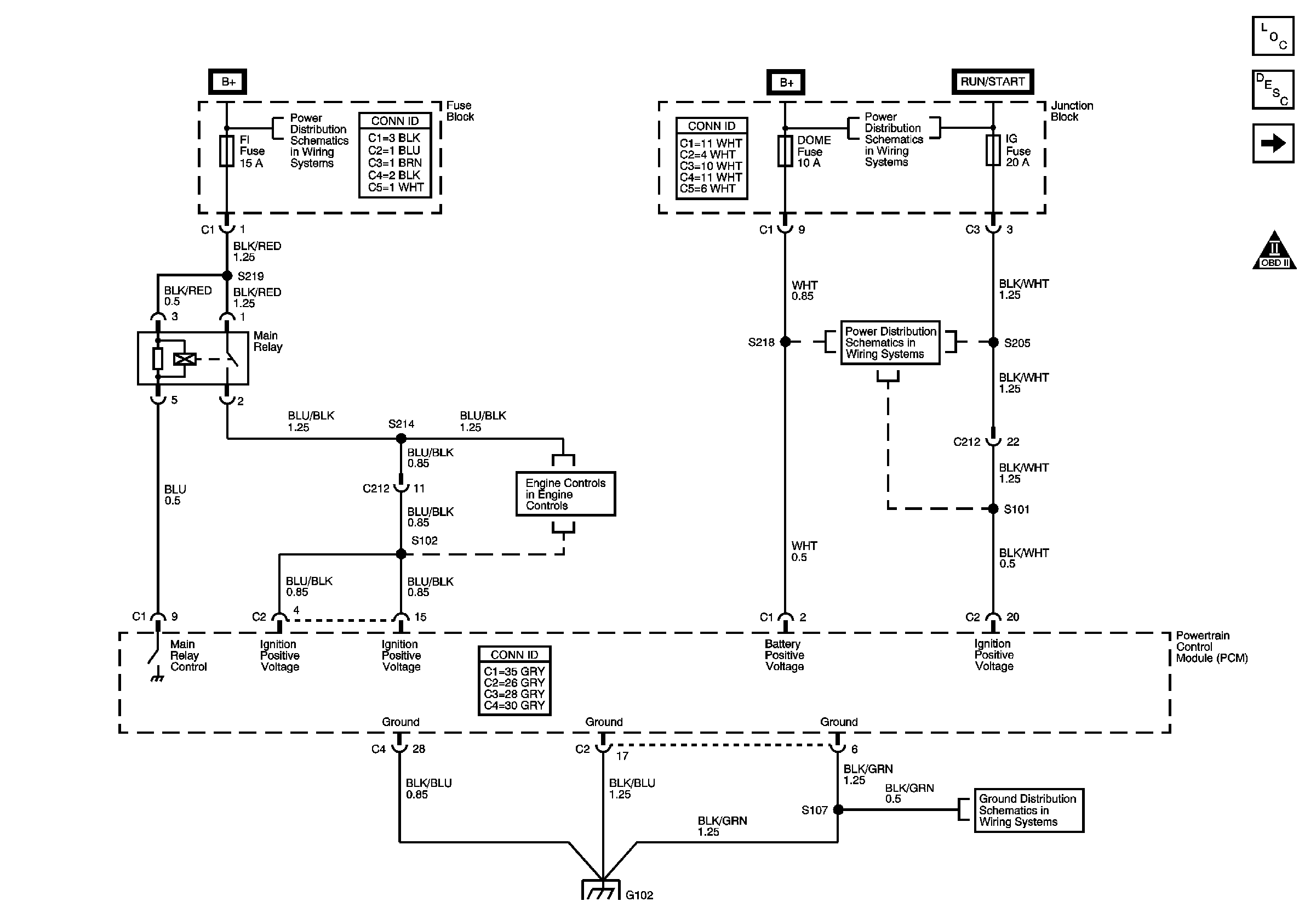
| Figure 1: |
Main Relay, Powertrain Control Module (PCM) Power
and Ground
|
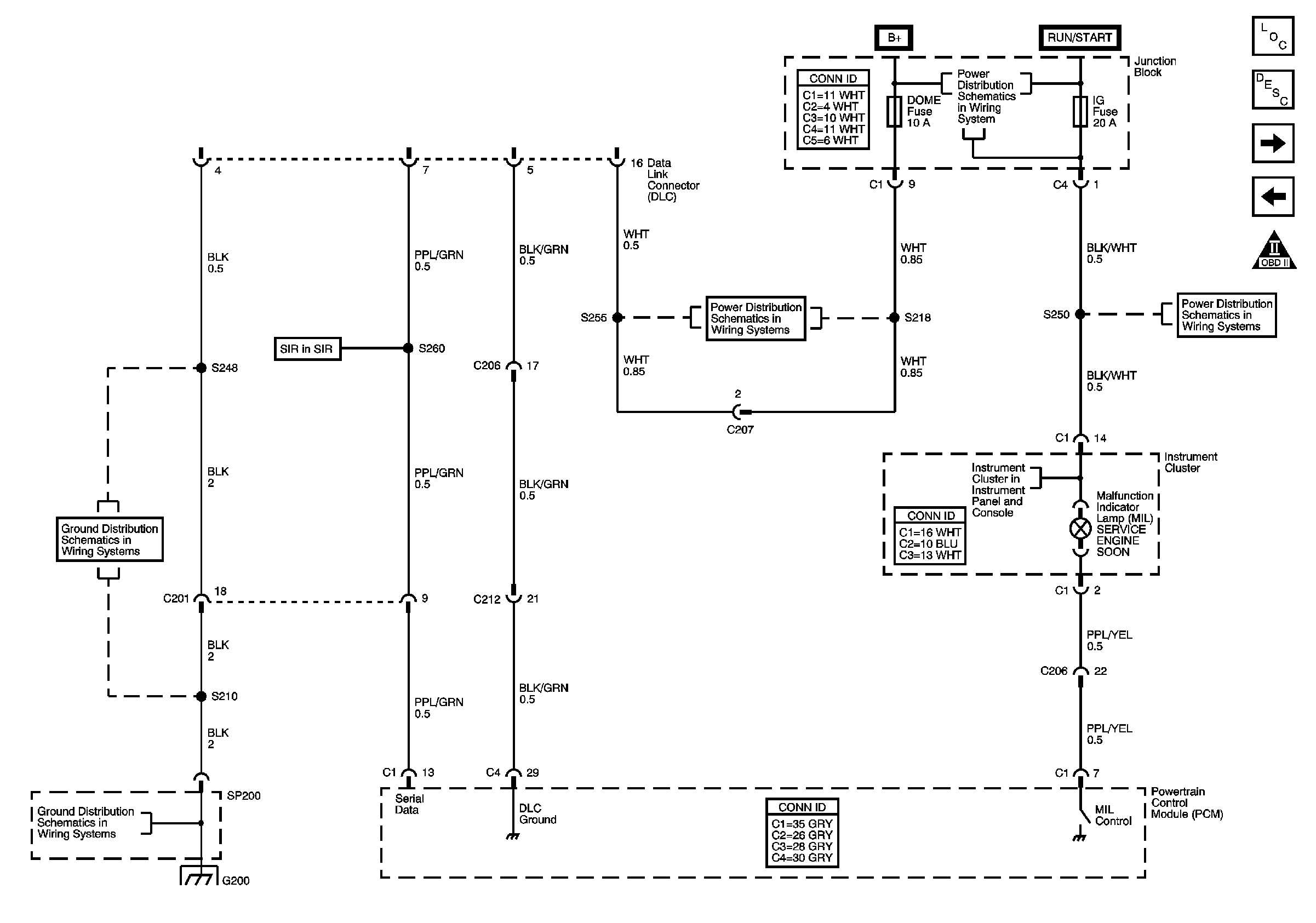
| Figure 2: |
Data Link Connector (DLC) and Malfunction Indicator
Lamp (MIL)
|
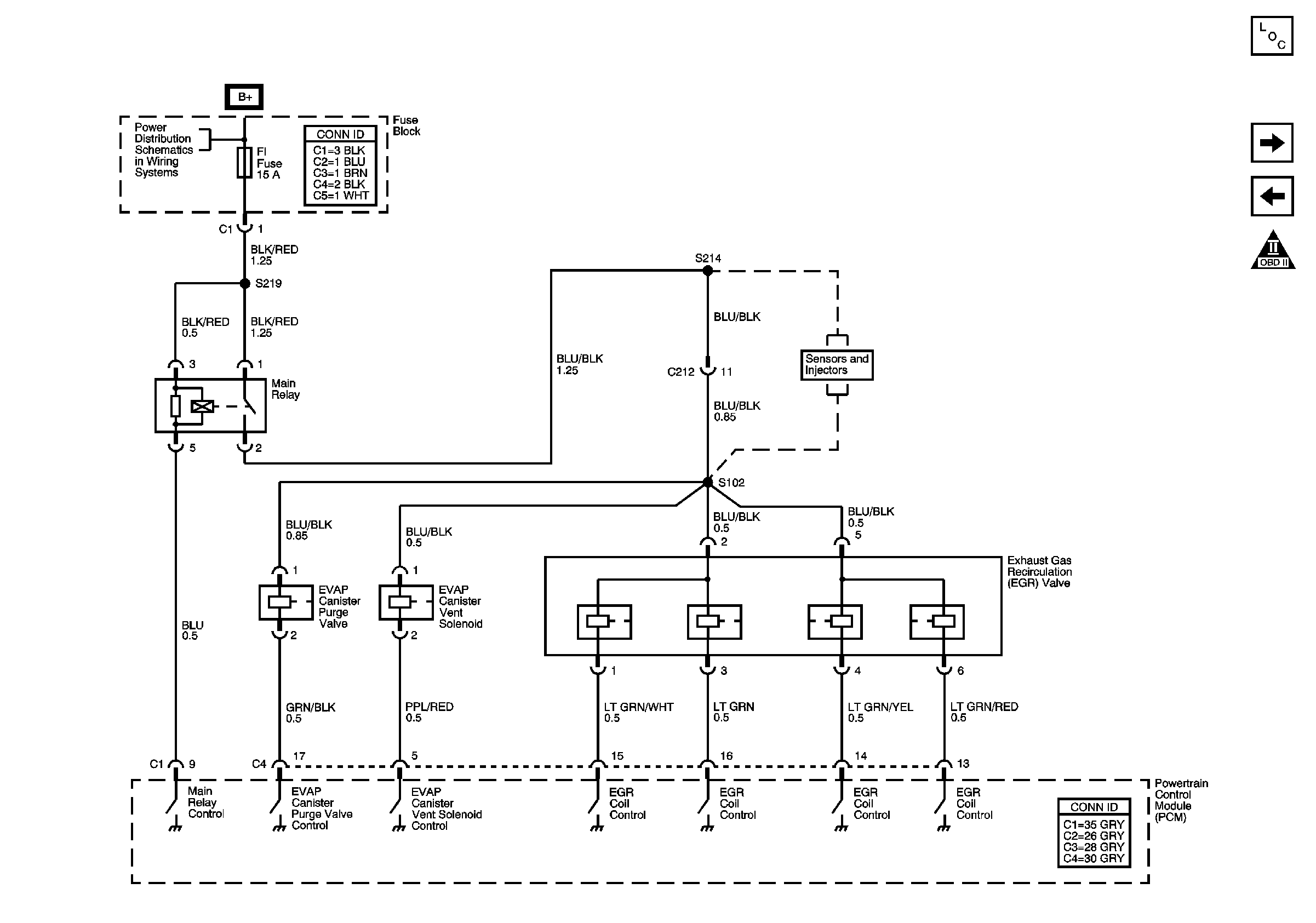
| Figure 3: |
Exhaust Gas Recirculation (EGR) Valve and EVAP
Solenoids
|
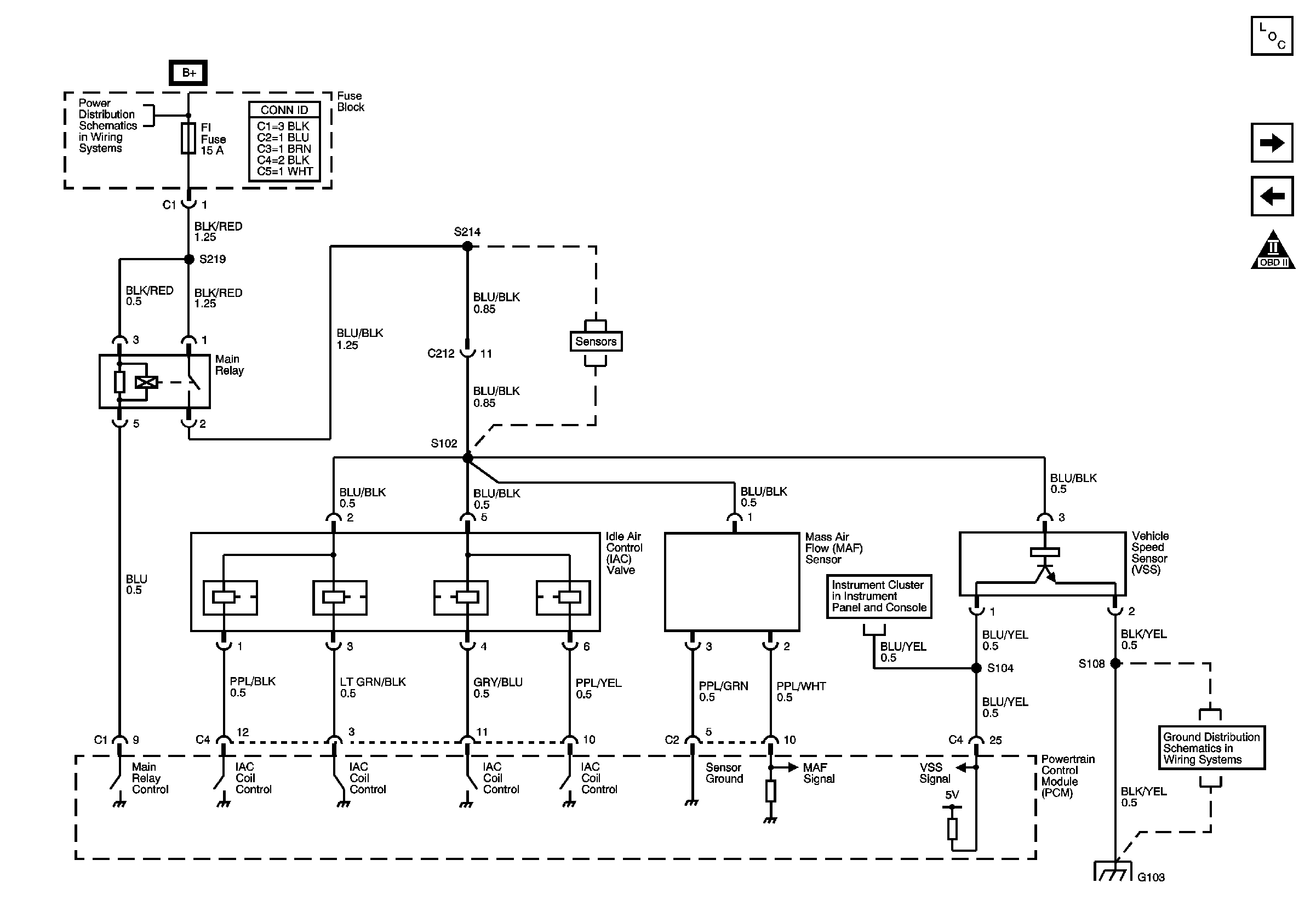
| Figure 4: |
Idle Air Control (IAC) Valve, Mass Air Flow (MAF)
Sensor, Vehicle Speed Sensor (VSS)
|
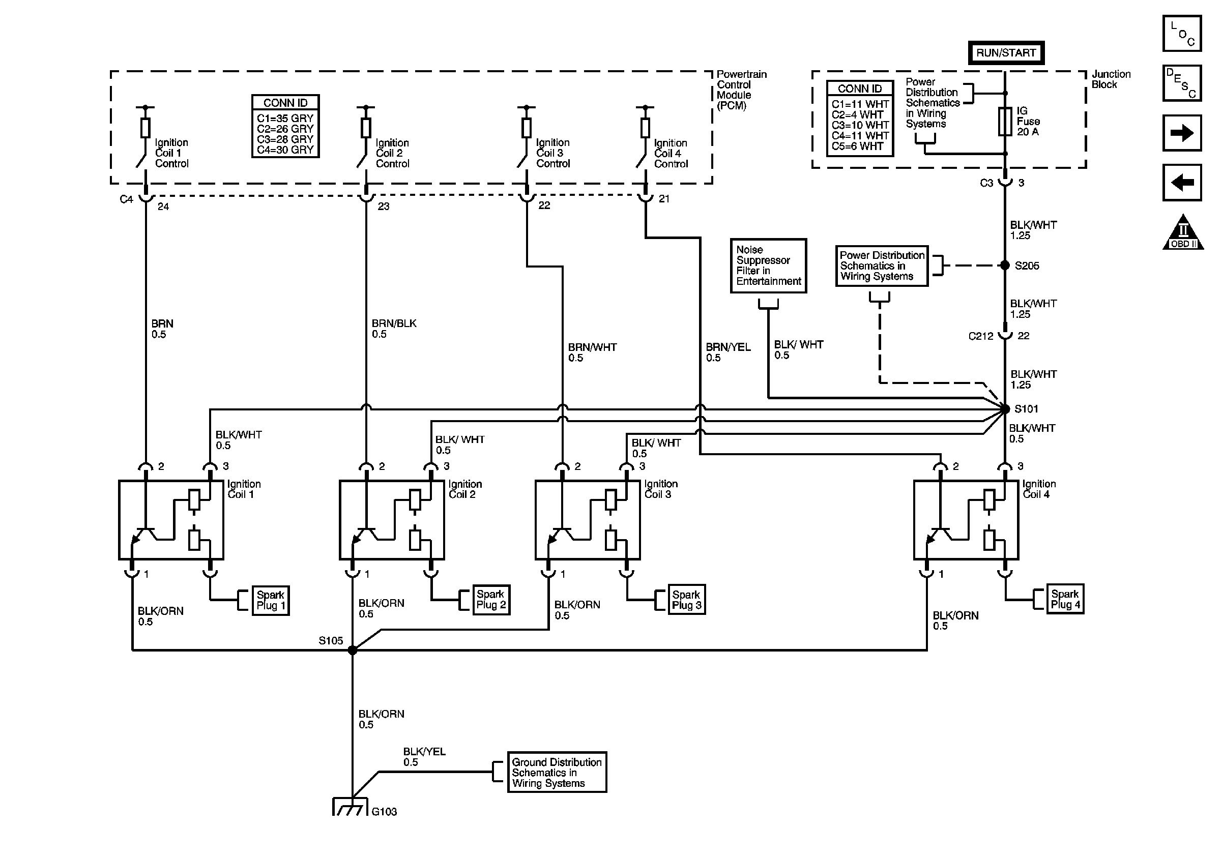
| Figure 5: |
Ignition System
|
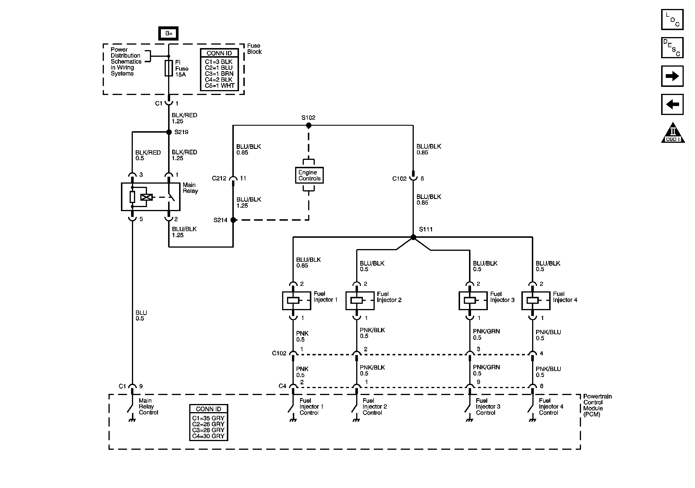
| Figure 6: |
Fuel Injectors
|
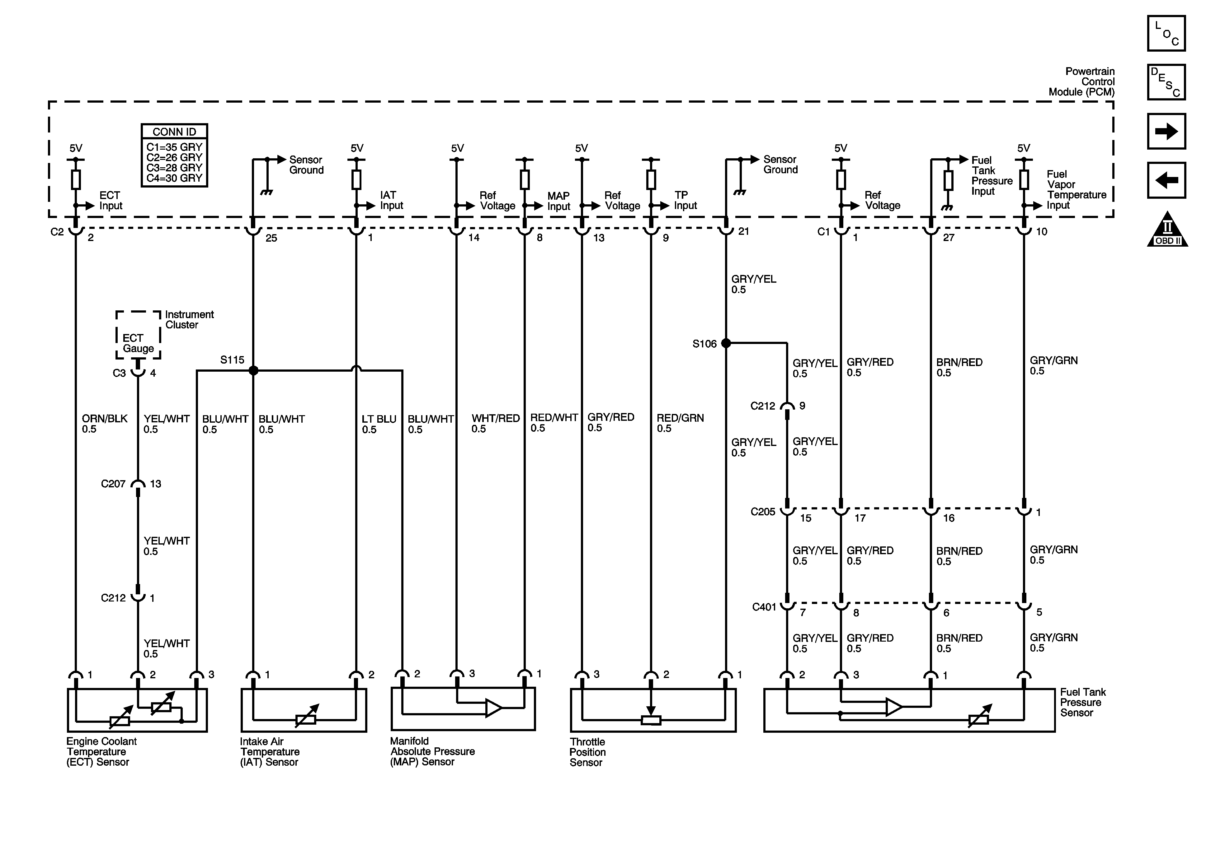
| Figure 7: |
ECT, IAT, MAP, TP and FTP Sensors
|
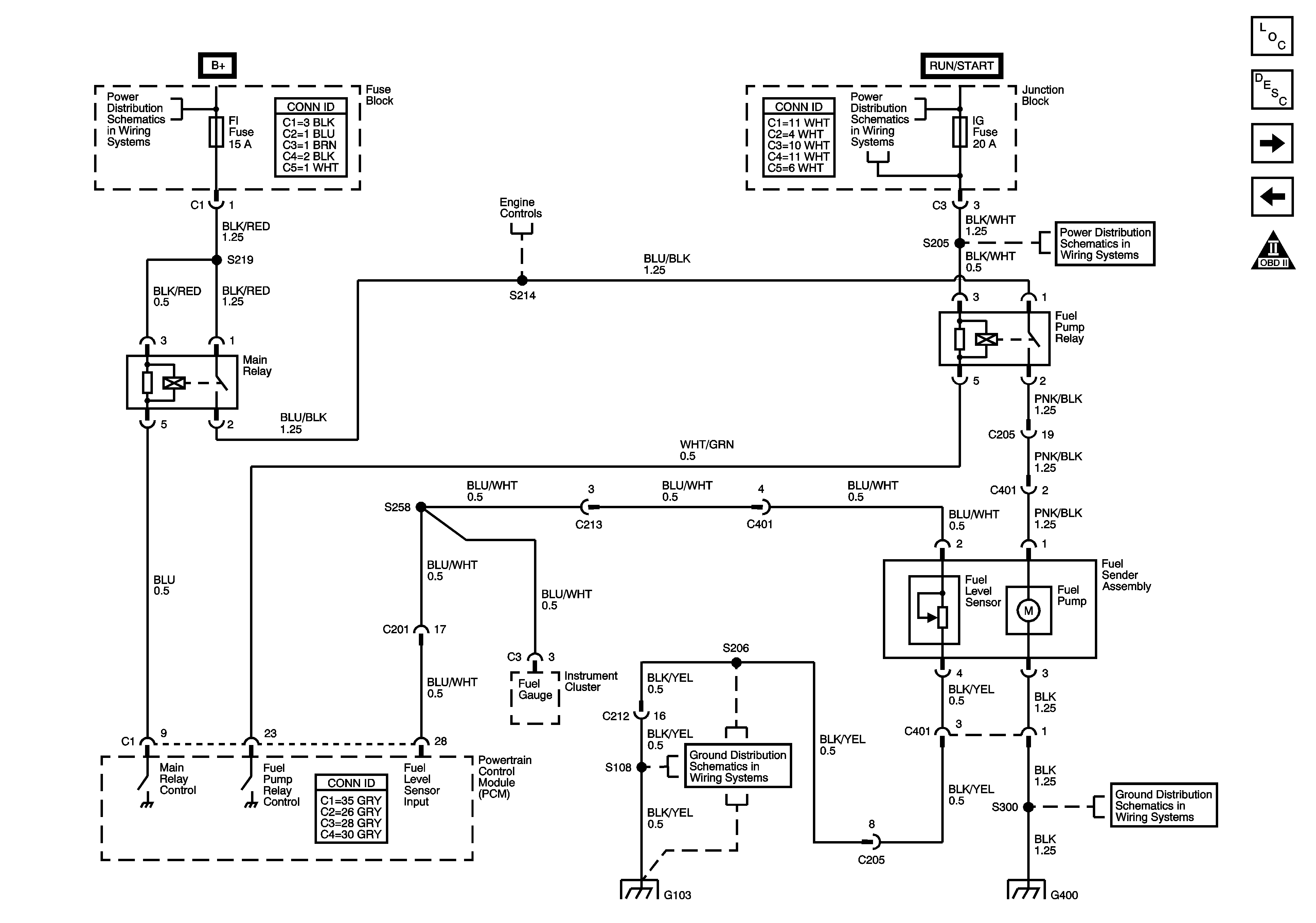
| Figure 8: |
Fuel Pump Relay and Fuel Sender Assembly
|
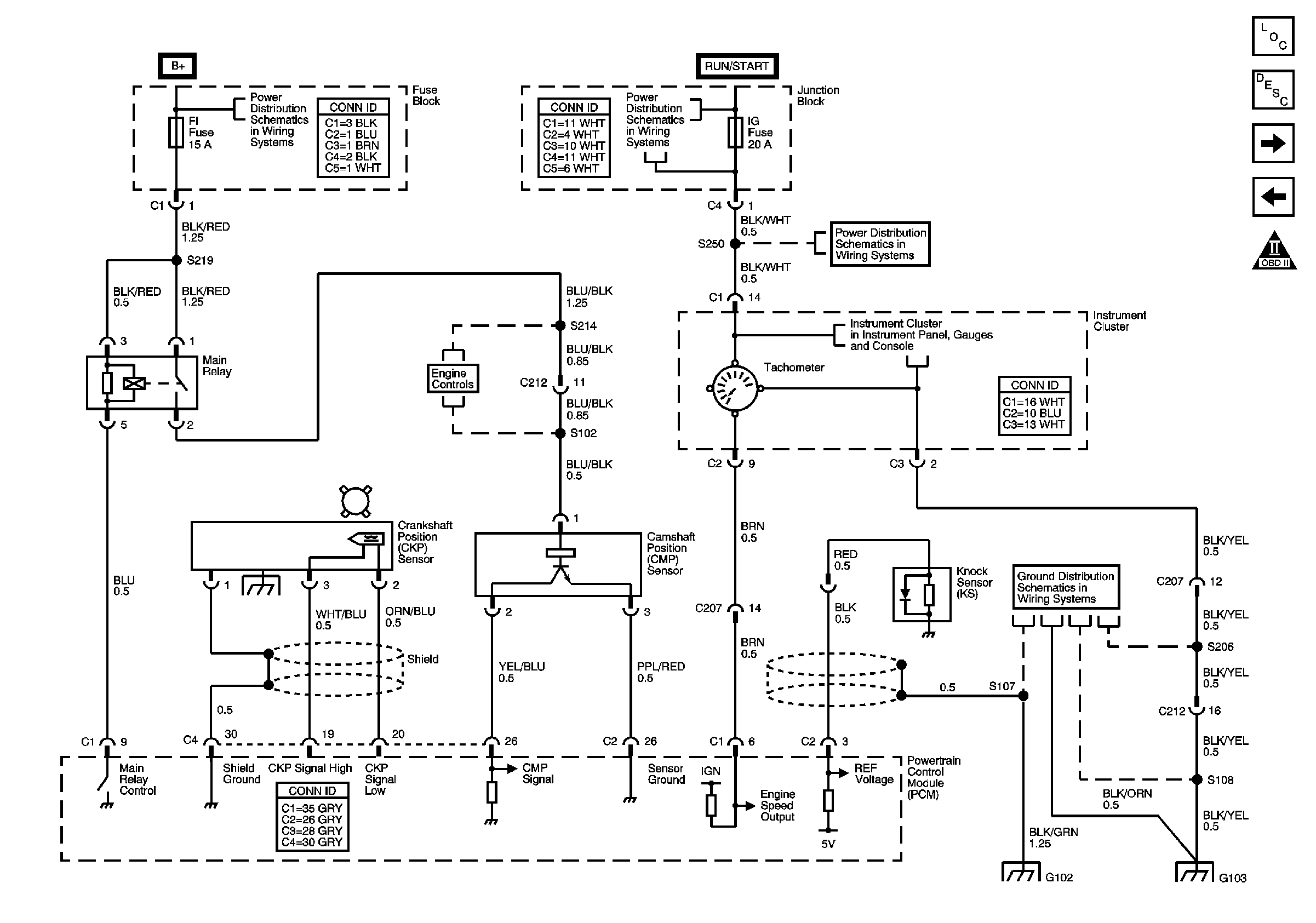
| Figure 9: |
Crankshaft Position (CKP), Camshaft Position (CMP)
and Knock Sensors (KS)
|
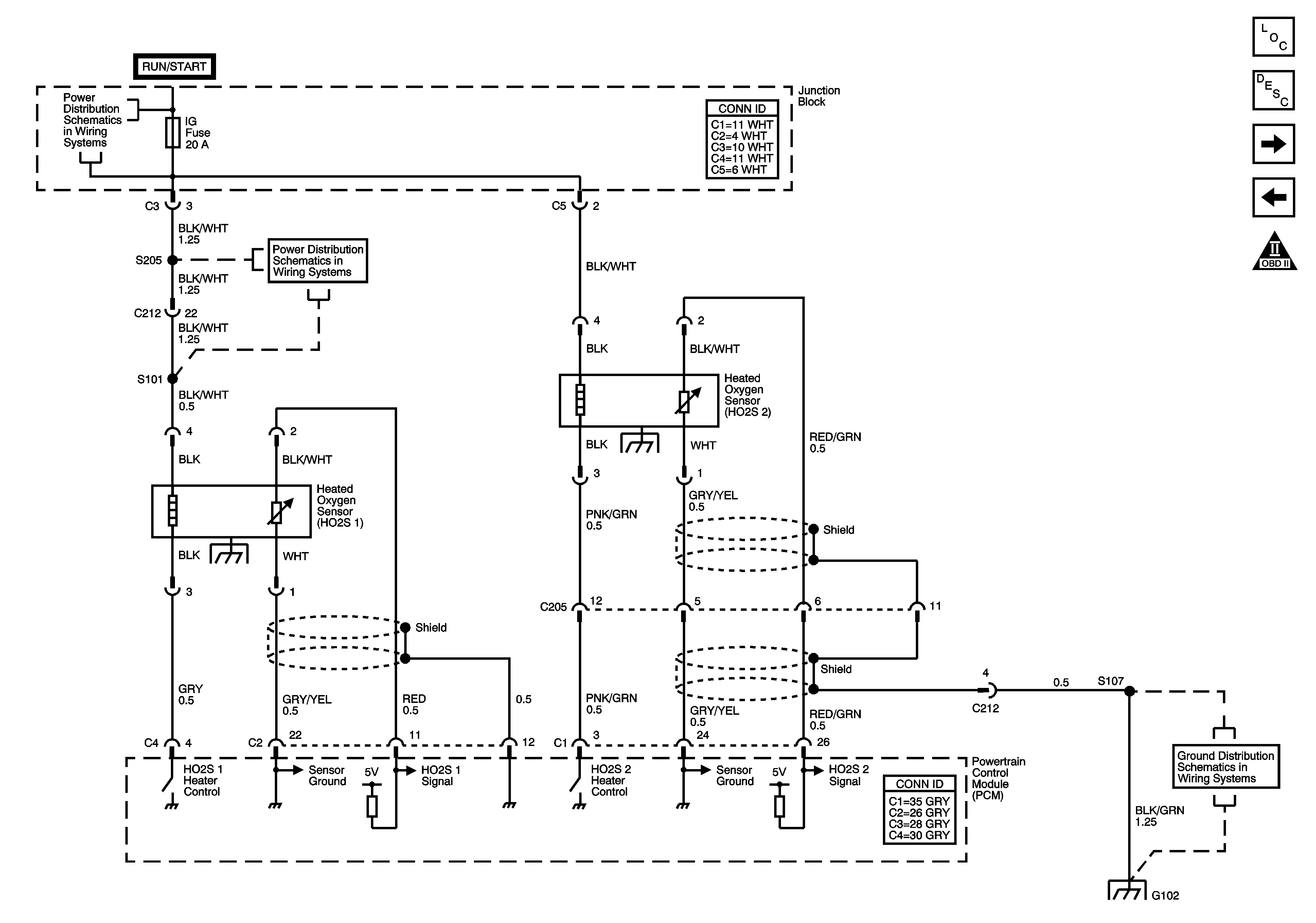
| Figure 10: |
Heated Oxygen Sensors (HO2S)
|
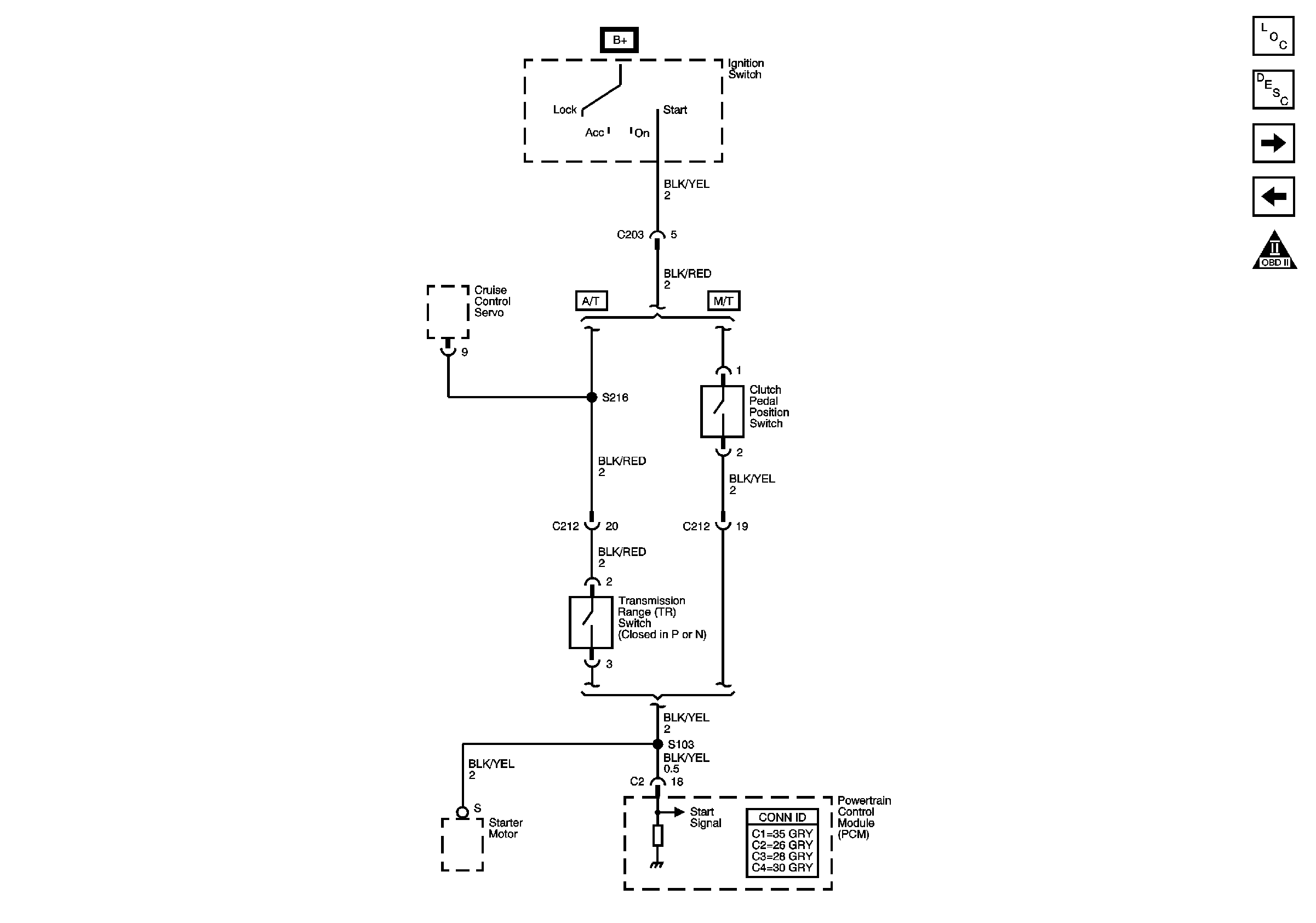
| Figure 11: |
Transmission Range Switch, Clutch Pedal Position
Switch
|
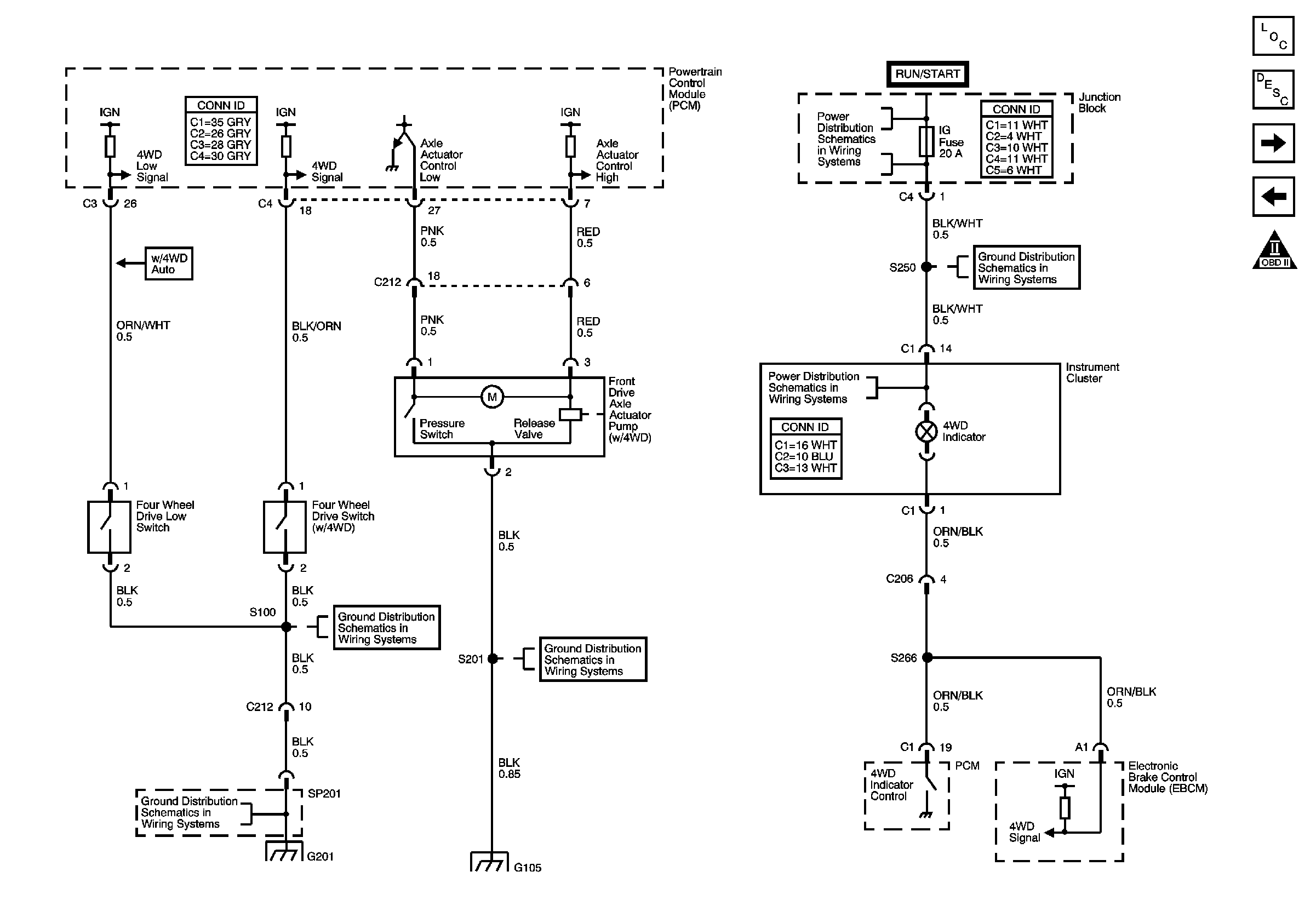
| Figure 12: |
Four Wheel Drive Switches and Front Drive Axle
Actuator Pump
|
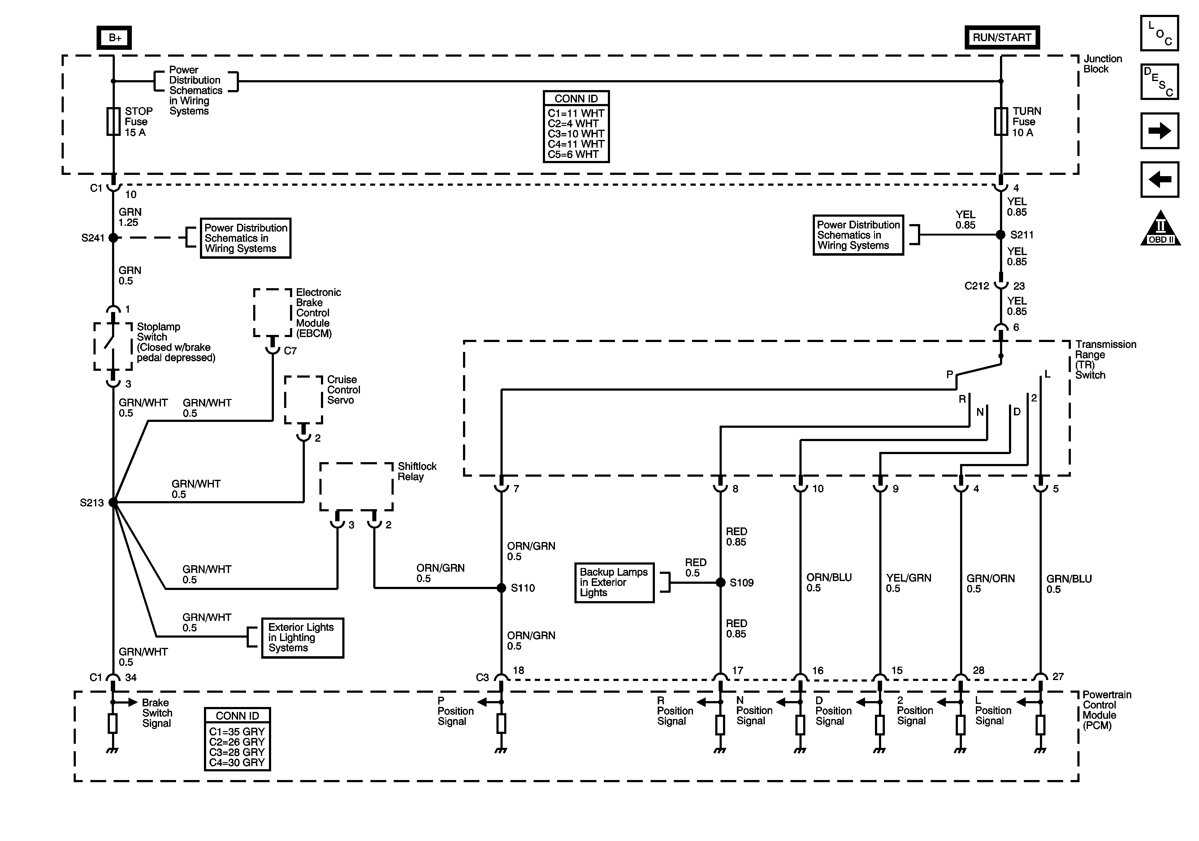
| Figure 13: |
Stoplamp Switch and Transmission Range Switch
|
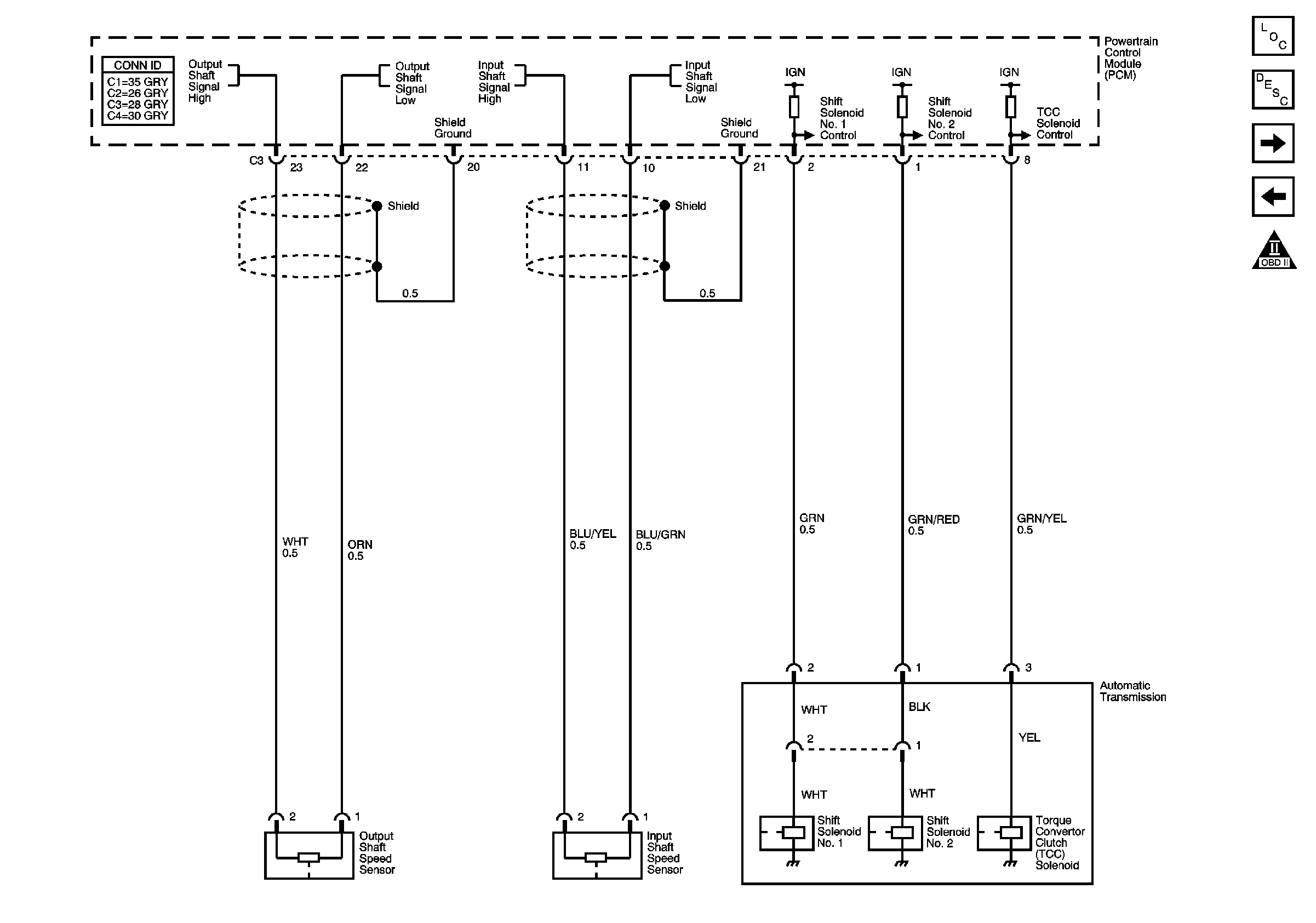
| Figure 14: |
Input and Output Shaft Speed Sensors, Torque Converter
Clutch (TCC) Solenoid
|
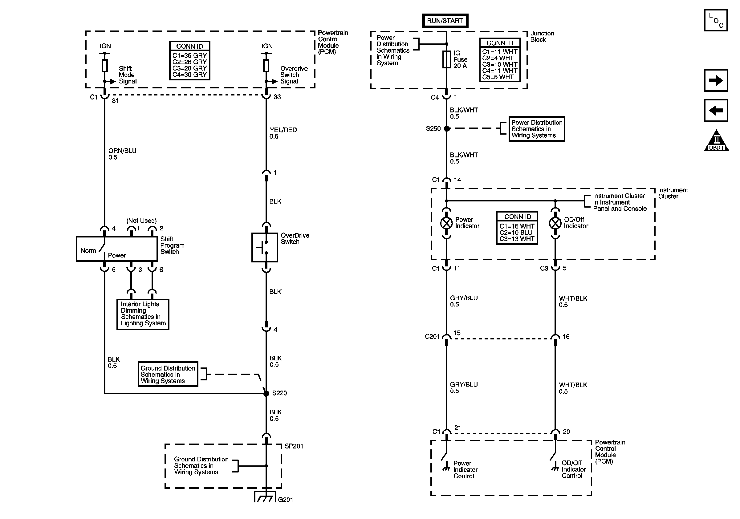
| Figure 15: |
Overdrive Switch and Shift Program Switch
|
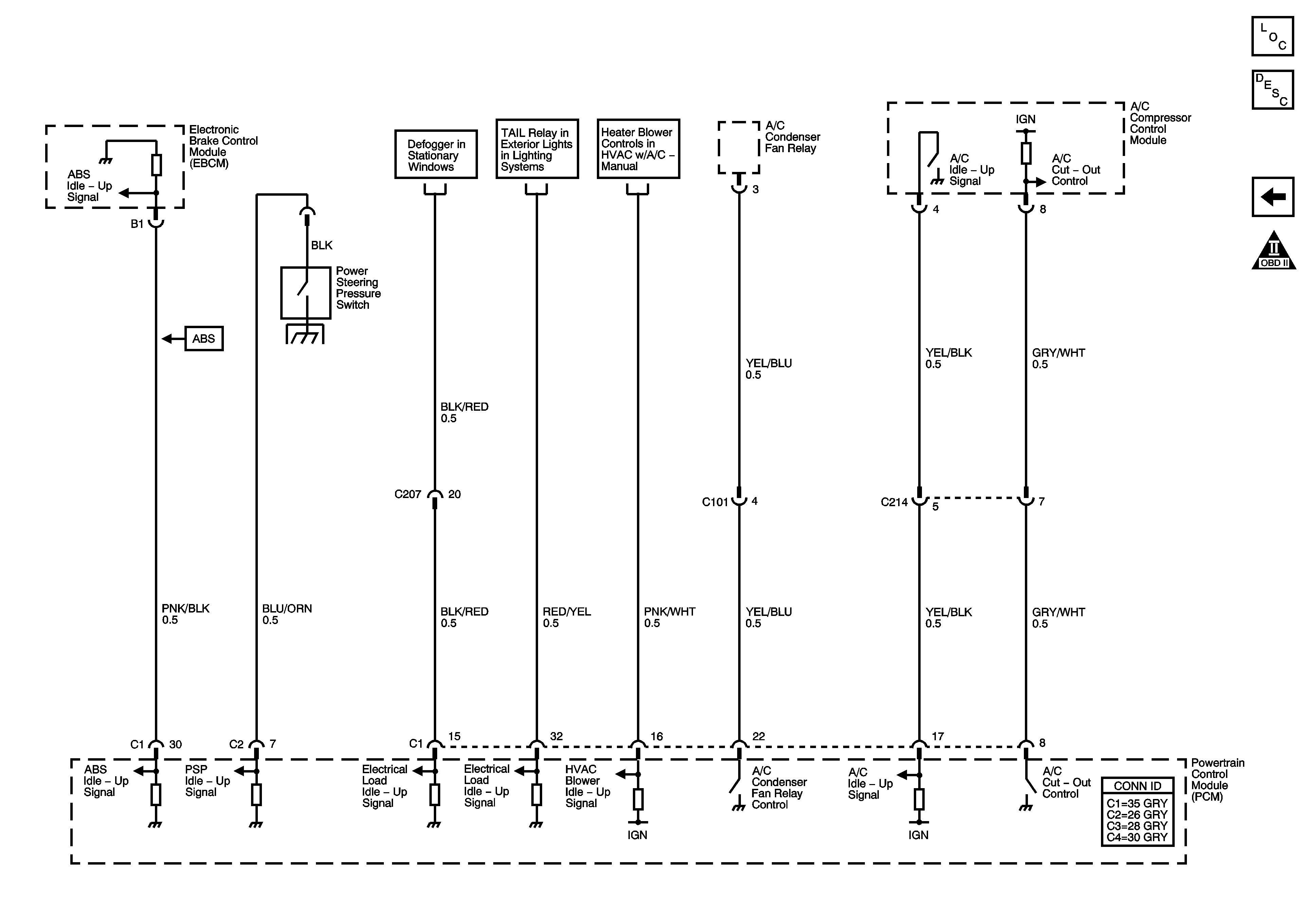
| Figure 16: |
Powertrain Control Module (PCM) Idle-Up Inputs
|