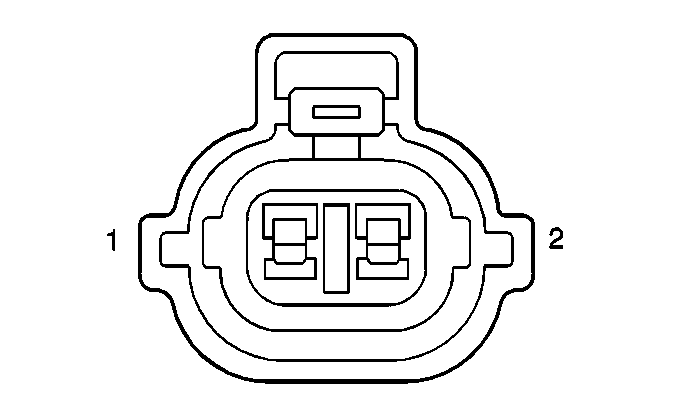
| |||||||
|---|---|---|---|---|---|---|---|
Connector Part Information |
| ||||||
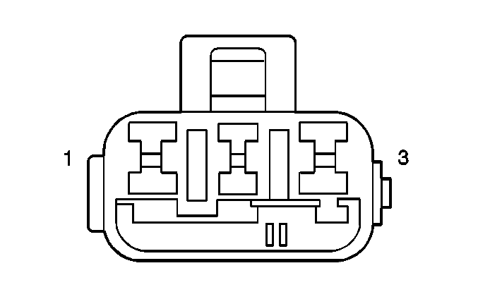
Pin | Wire Color | Function | |||||
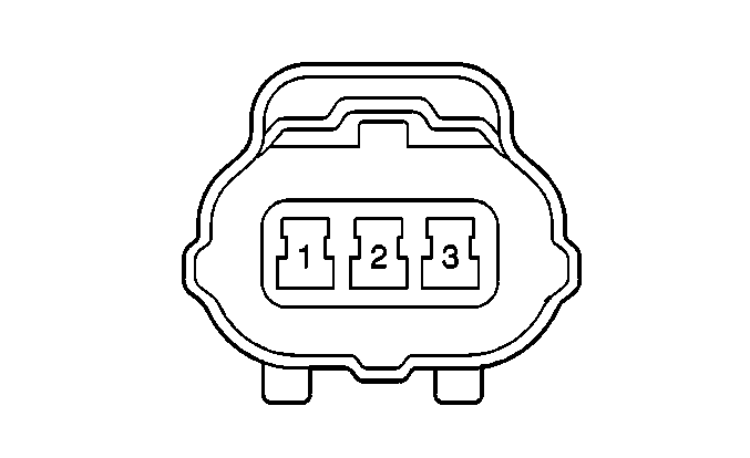
1 | BARE | Sensor Shield Ground | |||||
2 | ORN/BLU | CKP Sensor Signal-Low | |||||
3 | WHT/BLU | CKP Sensor Signal-High | |||||
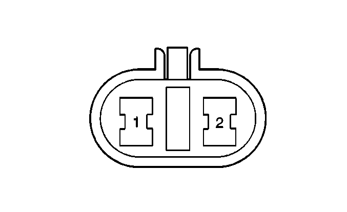
| |||||||
|---|---|---|---|---|---|---|---|
Connector Part Information |
| ||||||
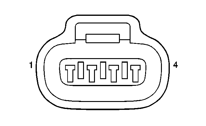
Pin | Wire Color | Function | |||||
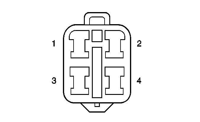
1 | GRY/YEL | Sensor Ground | |||||
2 | BLU/BLK | CMP Sensor Supply Voltage | |||||
3 | YEL/GRN | Sensor Signal High | |||||
4 | YEL/BLU | Sensor Signal Low | |||||
| |||||||
|---|---|---|---|---|---|---|---|
Connector Part Information |
| ||||||
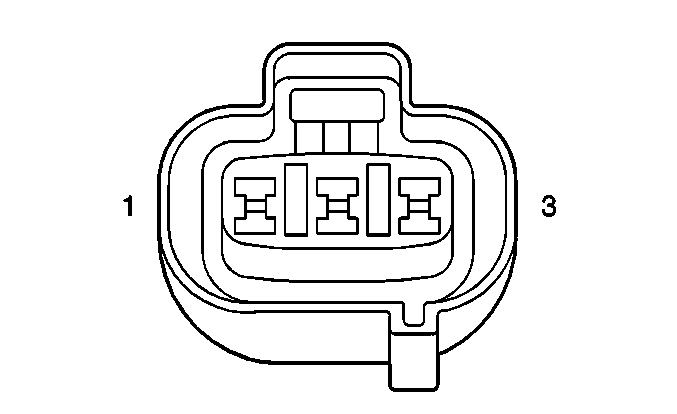
Pin | Wire Color | Function | |||||
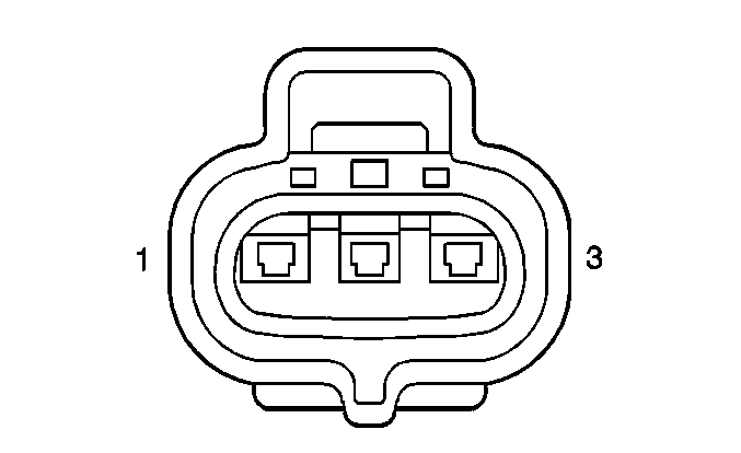
1 | ORN/BLK | Sensor Signal | |||||
2 | YEL/WHT | Temperature Indicator | |||||
3 | GRY/YEL | Sensor Ground | |||||
| |||||||
|---|---|---|---|---|---|---|---|
Connector Part Information |
| ||||||
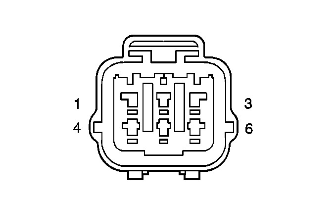
Pin | Wire Color | Function | |||||
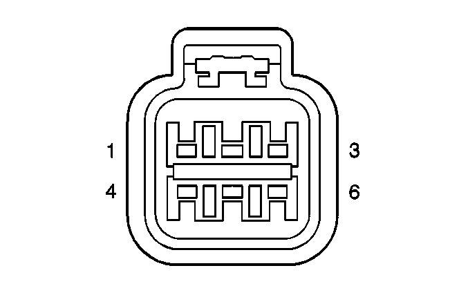
1 | GRN/WHT | EGR Coil Control | |||||
2 | BLU/ BLK | EGR Supply Voltage | |||||
3 | GRN | EGR Coil Control | |||||
4 | GRN/YEL | EGR Coil Control | |||||
5 | BLU/ BLK | EGR Supply Voltage | |||||
6 | GRN/RED | EGR Coil Control | |||||

| |||||||
|---|---|---|---|---|---|---|---|
Connector Part Information |
| ||||||
Pin | Wire Color | Function | |||||
1 | BLU/BLK | Purge Valve Supply Voltage | |||||
2 | GRN/BLK | Purge Valve Control | |||||
| |||||||
|---|---|---|---|---|---|---|---|
Connector Part Information |
| ||||||
Pin | Wire Color | Function | |||||
1 | BLU/BLK | Vent Solenoid Supply Voltage | |||||
2 | PPL/RED | Vent Solenoid Control | |||||
| |||||||
|---|---|---|---|---|---|---|---|
Connector Part Information |
| ||||||
Pin | Wire Color | Function | |||||
1 | GRY | Injector Control | |||||
2 | BLU/BLK | Injector Supply Voltage | |||||
|
| |||||||
|---|---|---|---|---|---|---|---|
Connector Part Information |
| ||||||
Pin | Wire Color | Function | |||||
1 | GRY/BLK | Injector Control | |||||
2 | BLU/BLK | Injector Supply Voltage | |||||
|
| |||||||
|---|---|---|---|---|---|---|---|
Connector Part Information |
| ||||||
Pin | Wire Color | Function | |||||
1 | GRY/WHT | Injector Control | |||||
2 | BLU/BLK | Injector Supply Voltage | |||||
|
| |||||||
|---|---|---|---|---|---|---|---|
Connector Part Information |
| ||||||
Pin | Wire Color | Function | |||||
1 | GRY/YEL | Injector Control | |||||
2 | BLU/BLK | Injector Supply Voltage | |||||
|
| |||||||
|---|---|---|---|---|---|---|---|
Connector Part Information |
| ||||||
Pin | Wire Color | Function | |||||
1 | GRY/GRN | Injector Control | |||||
2 | BLU/BLK | Injector Supply Voltage | |||||
|
| |||||||
|---|---|---|---|---|---|---|---|
Connector Part Information |
| ||||||
Pin | Wire Color | Function | |||||
1 | GRY/RED | Injector Control | |||||
2 | BLU/BLK | Injector Supply Voltage | |||||
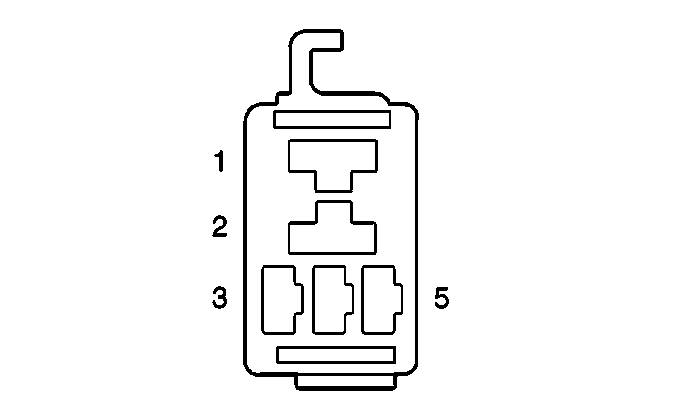
| |||||||
|---|---|---|---|---|---|---|---|
Connector Part Information |
| ||||||
Pin | Wire Color | Function | |||||
1 | BLU/BLK | Fuel Pump Relay Supply Voltage-Switch Side | |||||
2 | PNK/BLK | Fuel Pump Relay-Switch Side to Load | |||||
3 | BLK/WHT | Fuel Pump Relay Supply Voltage-Coil Side | |||||
4 | -- | Not Used | |||||
5 | WHT/GRN | Fuel Pump Relay Coil Control | |||||
| ||||||
|---|---|---|---|---|---|---|
Connector Part Information |
| |||||
Pin | Wire Color | Function | ||||
1 | PNK/BLK | Fuel Pump Supply Voltage | ||||
2 | BLU/WHT | Fuel Level Sensor Input | ||||
3 | BLK | Ground G-400 | ||||
4 | BLK/YEL | Sensor Ground | ||||
|
| ||||||
|---|---|---|---|---|---|---|
Connector Part Information |
| |||||
Pin | Wire Color | Function | ||||
1 | BRN/RED | Tank Pressure Input | ||||
2 | GRY/YEL | Sensor Ground | ||||
3 | GRY/RED | Reference Voltage | ||||
4 | GRY/GRN | Vapor Temperature Input | ||||
| |||||||
|---|---|---|---|---|---|---|---|
Connector Part Information |
| ||||||
Pin | Wire Color | Function | |||||
1 | GRY/YEL | HO2S Ground | |||||
2 | RED | HO2S Signal | |||||
3 | GRY | Heater Control | |||||
4 | BLU | Heater Supply Voltage | |||||
|
| |||||||
|---|---|---|---|---|---|---|---|
Connector Part Information |
| ||||||
Pin | Wire Color | Function | |||||
1 | BLU/YEL | HO2S Ground | |||||
2 | LT GRN/ BLU | HO2S Signal | |||||
3 | BLK/RED | Heater Control | |||||
4 | BLU | Heater Supply Voltage | |||||
|
| |||||||
|---|---|---|---|---|---|---|---|
Connector Part Information |
| ||||||
Pin | Wire Color | Function | |||||
1 | YEL | HO2S Ground | |||||
2 | BLU | HO2S Signal | |||||
3 | WHT/BLK | Heater Control | |||||
4 | BLU | Heater Supply Voltage | |||||
|
| |||||||
|---|---|---|---|---|---|---|---|
Connector Part Information |
| ||||||
Pin | Wire Color | Function | |||||
1 | YEL | HO2S Ground | |||||
2 | BRN | HO2S Signal | |||||
3 | PNK/WHT | Heater Control | |||||
4 | BLU | Heater Supply Voltage | |||||
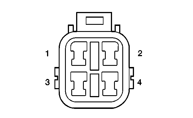
| |||||||
|---|---|---|---|---|---|---|---|
Connector Part Information |
| ||||||
Pin | Wire Color | Function | |||||
1 | GRY/ BLU | IAC Coil Control | |||||
2 | BLU/ BLK | IAC Supply Voltage | |||||
3 | LT GRN/ BLK | IAC Coil Control | |||||
4 | PPL/ YEL | IAC Coil Control | |||||
5 | BLU/ BLK | IAC Supply Voltage | |||||
6 | PPL/ BLK | IAC Coil Control | |||||
| |||||||
|---|---|---|---|---|---|---|---|
Connector Part Information |
| ||||||
Pin | Wire Color | Function | |||||
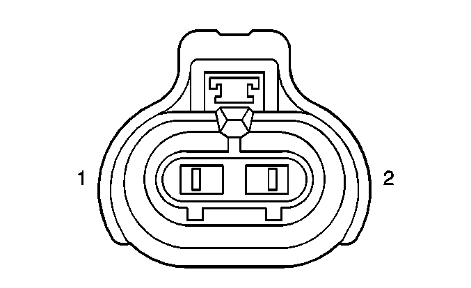
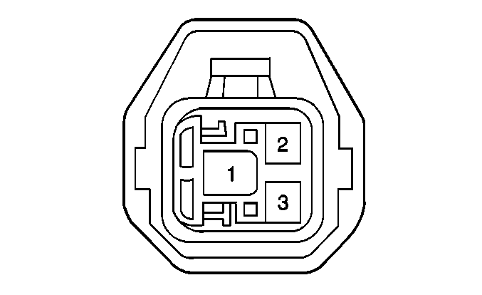
1 | GRY/YEL | Sensor Ground | |||||
2 | LT BLU | Sensor Input | |||||
| |||||||
|---|---|---|---|---|---|---|---|
Connector Part Information |
| ||||||
Pin | Wire Color | Function | |||||
1 | BLK/ORN | Ground G103 | |||||
2 | BRN | Ignition Coil Control | |||||
3 | BLK/WHT | Ignition Coil Supply Voltage | |||||
|
| |||||||
|---|---|---|---|---|---|---|---|
Connector Part Information |
| ||||||
Pin | Wire Color | Function | |||||
1 | BLK/ORN | Ground G103 | |||||
2 | BRN/BLK | Ignition Coil Control | |||||
3 | BLK/WHT | Ignition Coil Supply Voltage | |||||
|
| |||||||
|---|---|---|---|---|---|---|---|
Connector Part Information |
| ||||||
Pin | Wire Color | Function | |||||
1 | BLK/ORN | Ground G103 | |||||
2 | BRN/WHT | Ignition Coil Control | |||||
3 | BLK/WHT | Ignition Coil Supply Voltage | |||||
|
| |||||||
|---|---|---|---|---|---|---|---|
Connector Part Information |
| ||||||
Pin | Wire Color | Function | |||||
1 | BLK/ORN | Ground G103 | |||||
2 | BRN/YEL | Ignition Coil Control | |||||
3 | BLK/WHT | Ignition Coil Supply Voltage | |||||
|
| |||||||
|---|---|---|---|---|---|---|---|
Connector Part Information |
| ||||||
Pin | Wire Color | Function | |||||
1 | BLK/ORN | Ground G103 | |||||
2 | BRN/RED | Ignition Coil Control | |||||
3 | BLK/WHT | Ignition Coil Supply Voltage | |||||
|
| |||||||
|---|---|---|---|---|---|---|---|
Connector Part Information |
| ||||||
Pin | Wire Color | Function | |||||
1 | BLK/ORN | Ground G103 | |||||
2 | BLK/BRN | Ignition Coil Control | |||||
3 | BLK/WHT | Ignition Coil Supply Voltage | |||||
|
| |||||||
|---|---|---|---|---|---|---|---|
Connector Part Information |
| ||||||
Pin | Wire Color | Function | |||||
1 | PPL/WHT | MAF Signal | |||||
2 | GRY/YEL | Sensor Ground | |||||
3 | BLU/BLK | MAF Supply Voltage | |||||
|
| ||||||
|---|---|---|---|---|---|---|
Connector Part Information |
| |||||
Pin | Wire Color | Function | ||||
1 | BLK/RED | Main Relay Supply Voltage-Switch Side | ||||
2 | BLU/BLK | Main Relay Switch Side to Load | ||||
3 | BLK/RED | Main Relay Supply Voltage-Coil Side | ||||
4 | -- | Not Used | ||||
5 | BLU | Main Relay Coil Control | ||||
| |||||||
|---|---|---|---|---|---|---|---|
Connector Part Information |
| ||||||
Pin | Wire Color | Function | |||||
1 | RED/WHT | MAP Signal | |||||
2 | GRY/YEL | Sensor Ground | |||||
3 | GRY/RED | Reference Voltage | |||||
| |||||||
|---|---|---|---|---|---|---|---|
Connector Part Information |
| ||||||
Pin | Wire Color | Function | |||||
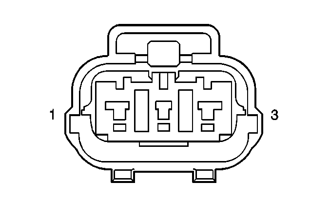
1 | GRY/RED | Reference Voltage | |||||
2 | RED/GRN | TP Signal | |||||
3 | GRY/YEL | Sensor Ground | |||||
| ||||||
|---|---|---|---|---|---|---|
Connector Part Information |
| |||||
Pin | Wire Color | Function | ||||
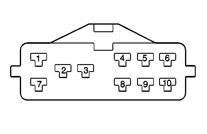
1 | -- | Not Used | ||||
2 | BLK/RED | Ignition Switch Start Signal | ||||
3 | BLK/YEL | Starter Motor Signal | ||||
4 | GRN/ORN | 2nd Gear Position Signal | ||||
5 | GRN/BLU | Low Position Signal | ||||
6 | YEL | Transmission Range Switch Supply Voltage | ||||
7 | ORN/GRN | Park Position Signal | ||||
8 | RED | Reverse Position Signal | ||||
9 | YEL/GRN | Drive Position Signal | ||||
10 | ORN/BLU | Neutral Position Signal | ||||
| |||||||
|---|---|---|---|---|---|---|---|
Connector Part Information |
| ||||||
Pin | Wire Color | Function | |||||
1 | GRN/RED | Shift Solenoid 2 Control | |||||
2 | GRN | Shift Solenoid 1 Control | |||||
3 | GRN/YEL | TCC Solenoid Control | |||||
|
| ||||||
|---|---|---|---|---|---|---|
Connector Part Information |
| |||||
Pin | Wire Color | Function | ||||
1 | BLU/YEL | VSS Signal | ||||
2 | BLK/YEL | Sensor Ground - G103 | ||||
3 | BLU/BLK | VSS Supply Voltage | ||||
