SMU - Revised Intake Manifold Replacement

| Subject: | Revised Intake Manifold Replacement |
| Models: | 2006 Buick Rainier |
| 2006 Chevrolet TrailBlazer Models |
| 2006 GMC Envoy Models |
| 2006 Saab 9-7X |
| with 4.2L Engine (VIN S - RPO LL8) |
This bulletin is being issued to revise the Intake Manifold Replacement procedure in the Engine Mechanical - 4.2L sub-section of the Service Manual. Please replace the current information in the Service Manual with the following information.
The following information has been updated within SI. If you are using a paper version of this Service Manual, please make a reference to this bulletin on the affected page.
Intake Manifold Replacement
Removal Procedure
- Relieve the fuel pressure. Refer to Fuel Pressure Relief.
- Remove the throttle body. Refer to Throttle Body Assembly Replacement for the 4.2L engine.
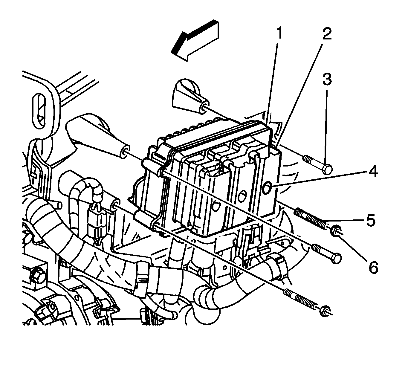
- Remove the powertrain control module (PCM) retaining bolts (3) and nuts (6).
- Remove the PCM. Refer to Powertrain Control Module Replacement.
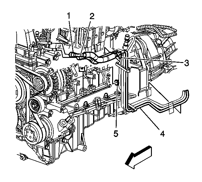
- Disconnect the fuel feed pipe (1) from the fuel rail. Refer to Quick Connect Fitting-Metal Collar.
- Disconnect the integral clip (3) from the wire harness bracket.
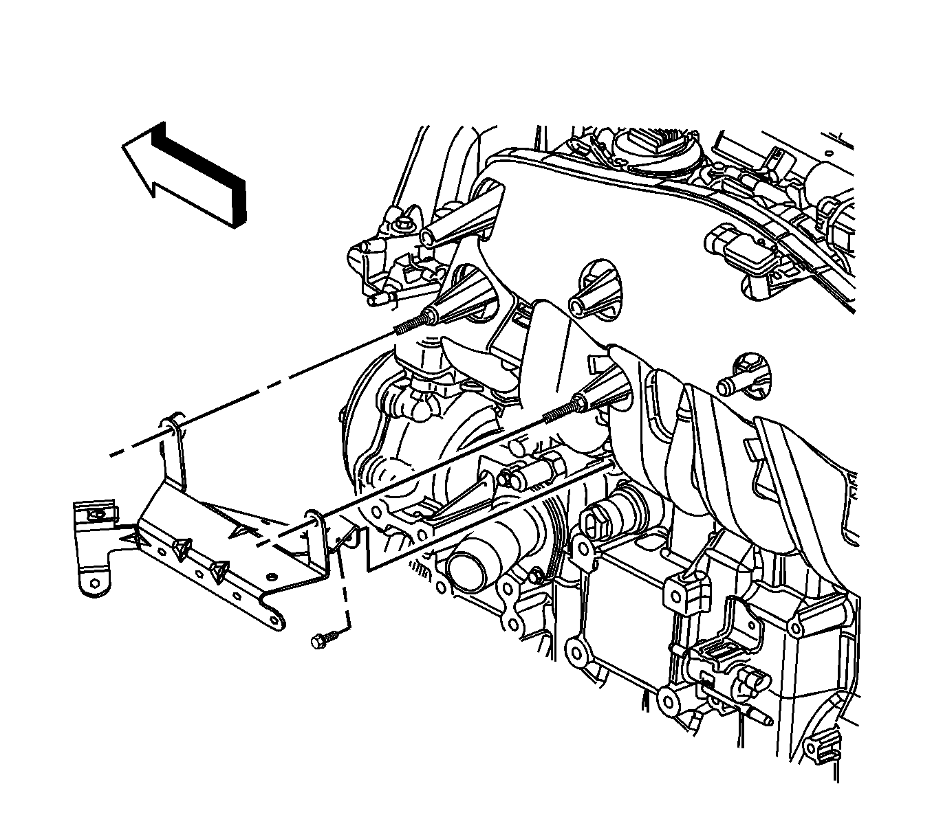
- Remove the engine wire harness bracket bolt.
- Remove the electrical harness and vacuum lines from the intake manifold.
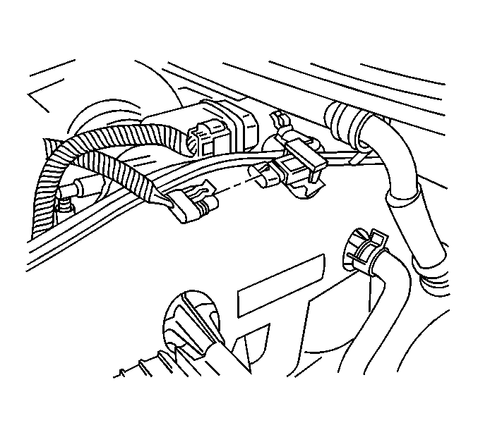
- Disconnect the manifold absolute pressure (MAP) sensor electrical connector.
- Disconnect the crankcase ventilation hose from the intake manifold.
- Disconnect the vacuum brake booster hose at the intake manifold.
- Remove the generator. Refer to Generator Replacement.
- Loosen the intake manifold bolts.
- Remove the intake manifold.
Notice: Refer to Fuel and Evaporative Emission/Hose/Pipe Connection Cleaning Notice.
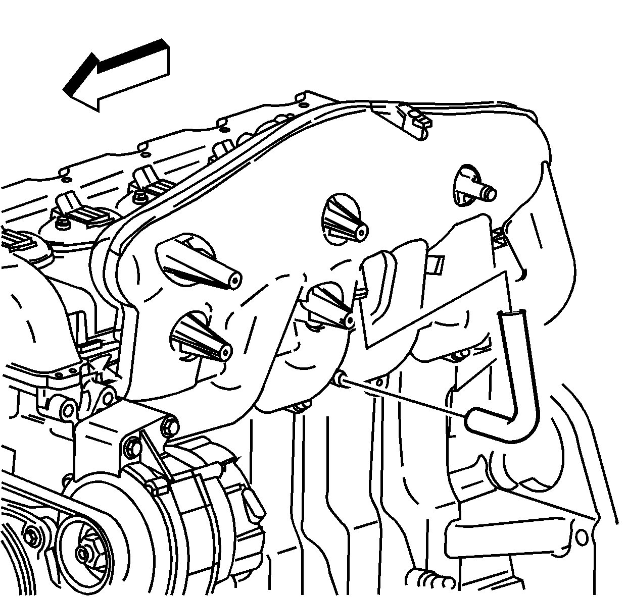
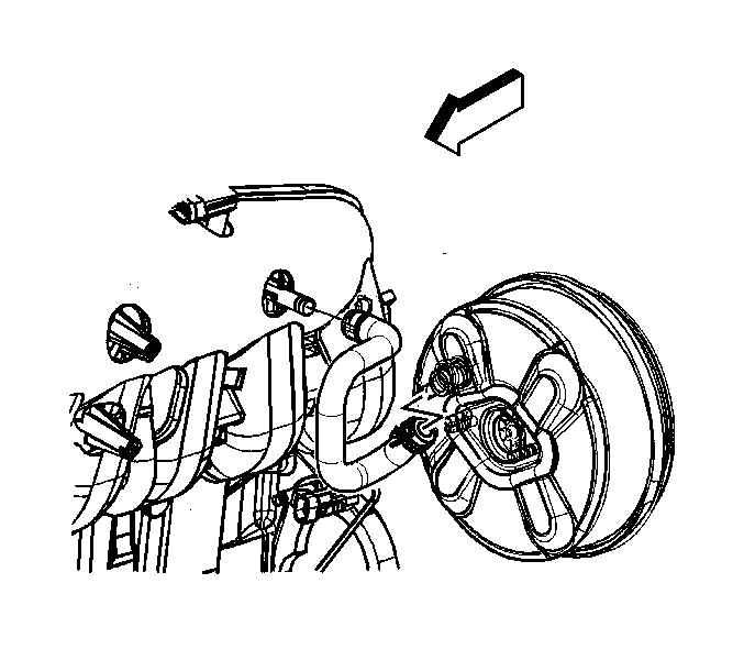
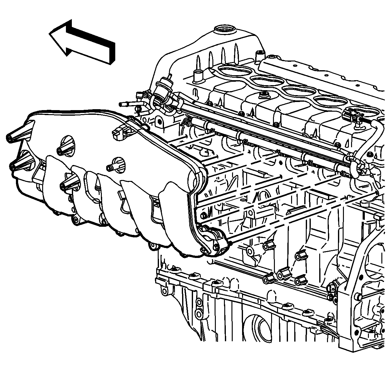
Important: The intake manifold bolts are captured within the intake manifold. Do not attempt to remove the bolts from the intake manifold.
Installation Procedure
- Install a new intake manifold gasket to the intake manifold.
- Install the intake manifold onto the engine and secure the manifold with the bolts.
- Install the generator. Refer to Generator Replacement.
- Install the vacuum brake booster hose to the intake manifold.
- Lubricate the inner diameter of the crankcase ventilation hose. Refer to Sealers, Adhesives, and Lubricants for the correct part number.
- Install the crankcase ventilation hose.
- Connect the MAP sensor electrical connector.
- Install the electrical harness and vacuum lines to the intake manifold.
- Install the engine electrical harness bracket bolt.
- Connect the integral clip (3) to the wire harness bracket.
- Connect the fuel feed pipe (1) to the fuel rail. Refer to Quick Connect Fitting Service -- Metal Collar.
- Install the PCM mounting studs (5) to the intake manifold.
- Install the PCM (1) onto the studs (5).
- Install the PCM retaining bolts (3).
- Install the PCM retaining nuts (6).
- Install the PCM harness connectors (2) to the PCM body.
- Tighten the PCM harness connector retaining bolts (4).
- Install the throttle body. Refer to Throttle Body Assembly Replacement for the 4.2L engine.
- Connect the negative battery cable. Refer to Battery Negative Cable Disconnection and Connection.
- Inspect for leaks using the following procedure:

Notice: Refer to Fastener Notice
Tighten
Tighten the intake manifold bolts to 10 N·m (89 lb in).


Tighten
Tighten the bolt to 10 N·m (89 lb in).


Tighten
Tighten the studs to 6 N·m (53 lb in).
Tighten
Tighten the bolts to 8 N·m (71 lb in).
Tighten
Tighten the nuts to 8 N·m (71 lb in).
Tighten
Tighten the bolts to 8 N·m (71 lb in).
| 20.1. | Turn ON the ignition, with the engine OFF for 2 seconds. |
| 20.2. | Turn OFF the ignition, for 10 seconds. |
| 20.3. | Turn ON the ignition, with the engine OFF. |
| 20.4. | Inspect for fuel leaks. |
