Diagnostic Instructions
Circuit/System Description
This ignition system uses individual ignition module/coil assemblies for each cylinder. The engine control module (ECM) controls the spark events by transmitting the timing pulses on the ignition control (IC) circuits to the individual ignition module/coil
assemblies in firing order sequence. Each ignition module/coil has the following circuits:
| • | An ignition 1 voltage circuit |
| • | A low reference circuit |
Diagnostic Aids
| • | This test procedure requires that the vehicle battery has passed a load test and is completely charged. |
| • | There is an adequate supply of fuel in the fuel tank. |
| • | When disconnecting electrical connectors or removing fuses and relays from a fuse block, always inspect both mating electrical terminals for corrosion and terminal tightness. |
| • | Use the
J 35616
for any test that requires probing the underhood fuse block terminals, component wire harness terminals, or the ECM wire harness terminals. |
Reference Information
Schematic Reference
Engine Controls Schematics
Connector End View Reference
Electrical Information Reference
Scan Tool Reference
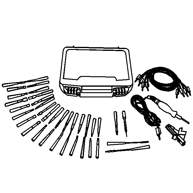
Special Tools Required
| • | J 35616
Connector Test Adapter Kit |
Circuit/System Verification
Observe the Engine Controls Schematic for the ignition module/coils, and review the Ignition System Specifications to verify the following concerns:
| • | The ignition modules/coils are correctly wired and connected |
| • | The proper spark plug type |
| • | The proper spark plug gap and torque |
| • | The proper ohm values for the spark plug wires |
Circuit/System Testing
- Turn OFF the ignition.
Important: This engine application uses 2 fuses, one for each bank, to supply ignition 1 voltage to the ignition module/coil assemblies and also to the fuel injectors. A good indication that a fuse is open is that all 4 misfire
counters are incrementing on one side of the engine
- Inspect both fuses that supply ignition voltage to the ignition module/coils.
| ⇒ | If a fuse is open, test all 8 ignition voltage circuits to the ignition module/coils or the fuel injectors on the engine bank, for a short to ground. |
- Disconnect the 4 ignition module/coil, and the 4 fuel injector electrical connectors, for the engine bank that has the open fuse.
- Replace the open fuse with a new fuse.
- Ignition ON, engine OFF.
- Reconnect each ignition module/coil, and fuel injector electrical connectors, one at a time.
| ⇒ | If the fuse opens when connecting an ignition module/coil or fuel injector electrical connector, then replace the component that caused the fuse to open. |
- Ignition OFF, disconnect the appropriate ignition module/coil electrical connector.
- Ignition ON, verify that a test lamp illuminates between the ignition voltage circuit and ground.
| ⇒ | If the test lamp does not illuminate test the ignition voltage circuit for an open/high resistance. |
- Verify that a test lamp illuminates between the ignition module/coil ground circuit and B+.
| ⇒ | If the test lamp does not illuminate, test the ignition module/coil ground circuit for an open/high resistance. |
- Inspect and measure the resistance of the spark plug wire. Refer to
Spark Plug Wire Inspection
and
Ignition System Specifications
.
| ⇒ | If the resistance value is not within the specified range, or does not pass the inspection, replace the spark plug wire. |
- Exchange the misfiring cylinder, ignition module/coil assembly with the ignition module/coil assembly from a non-misfiring cylinder.
- Start and idle the engine. Observe the misfire counters on the scan tool.
| ⇒ | If the misfire transfers with the suspect ignition module/coil, then replace the ignition module/coil assembly. |
| ⇒ | If the misfire does not transfer with the suspect ignition module/coil, then measure the resistance
of the IC circuit. The IC circuit should measure less than 5 ohms. If the circuit tests normal, replace the ECM. |
Component Testing
| • | Use the Spark Plug Inspection procedure to verify the integrity of the spark plugs. Refer to
Spark Plug Inspection
. Replace the spark plug if necessary. |
| | Important: An erratic or weak spark is considered a no spark condition.
|
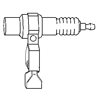
| • | Use the
J 26792
to verify the output of each ignition module/coil. If no spark is detected across the gap of the spark plug tester, then replace the ignition module/coil assembly. |
Repair Instructions
Perform the
Diagnostic Repair Verification
after completing the diagnostic procedure.
