For 1990-2009 cars only
Special Tools
| • | J 8001 Dial Indicator Set |
| • | J 8087 Cylinder Bore Gage |
| • | J 45059 Angle Meter |
- Clean the sealing material from all gasket mating surfaces.
- Clean the engine block with a cleaning solution.
- Flush the engine block with clean water.
- Clean the oil passages.
- Coat the cylinder bores and the machined surfaces with engine oil.
- Inspect the threaded holes. Clean the holes with a tap, if needed.
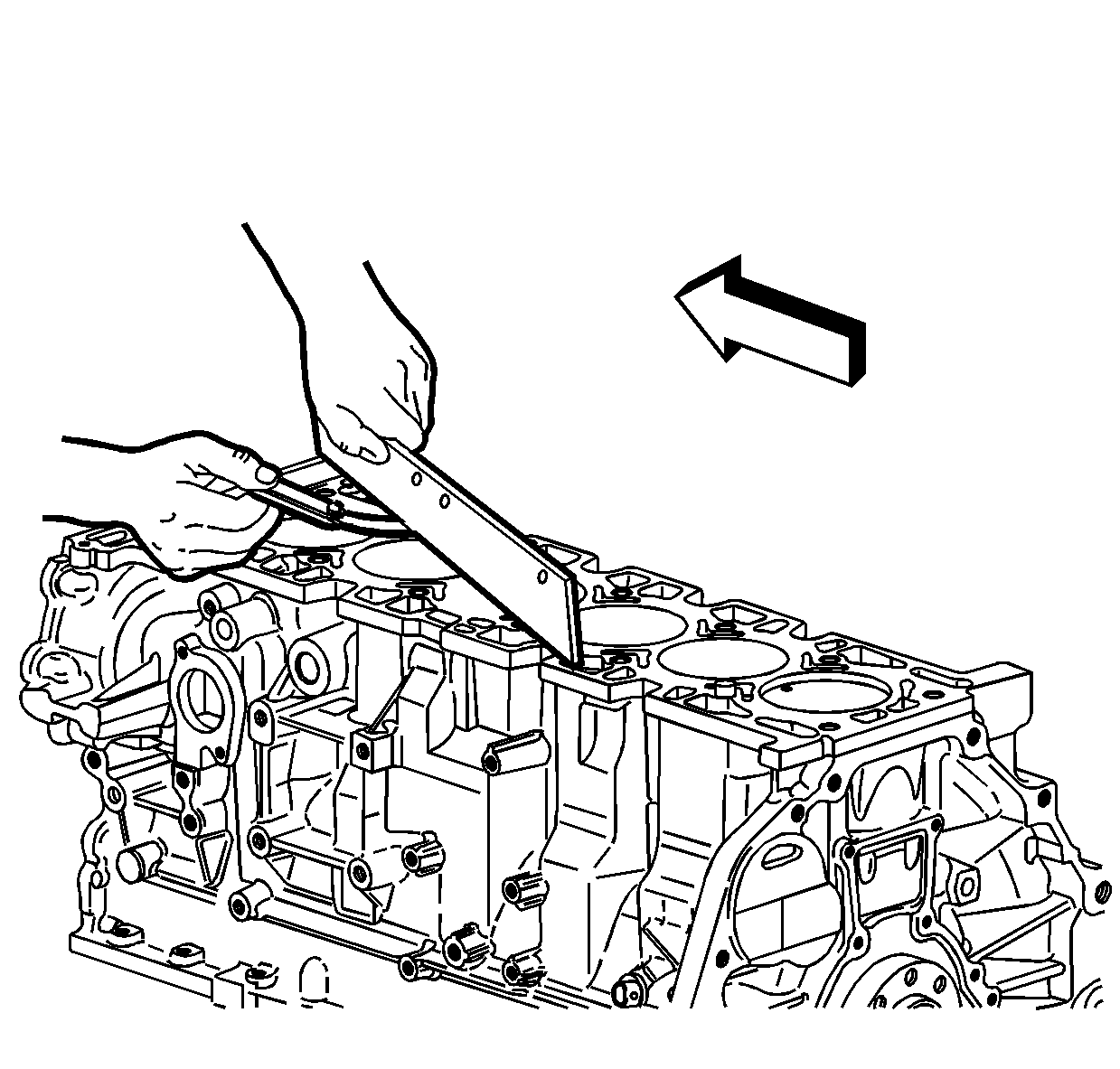
- Use a straight edge and a feeler gage to check the deck surface for flatness. Carefully remove any minor irregularities. Replace the block if there is more than 0.08 mm (0.003 in) gap.
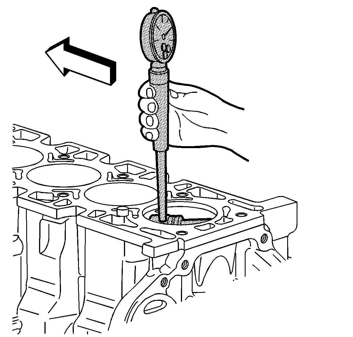
- Inspect the cylinder bores. Use J 8087 gage to measure the cylinder bore. Inspect the bores for the following conditions:
- Replace the cylinder sleeve if the bore is out of specification.
- Inspect the oil pan rail for nicks. Use a flat file to remove an nicks.
- Inspect the front cover attaching area for nicks. Use a flat file to remove any nicks.
- Inspect the mating surfaces of the transmission case.
- Use the following procedure to measure the engine block flange runout at the mounting bolt hole bosses:
- Remove the crankshaft.
- Re-install the crankshaft bearing caps, stiffener, and bolts.
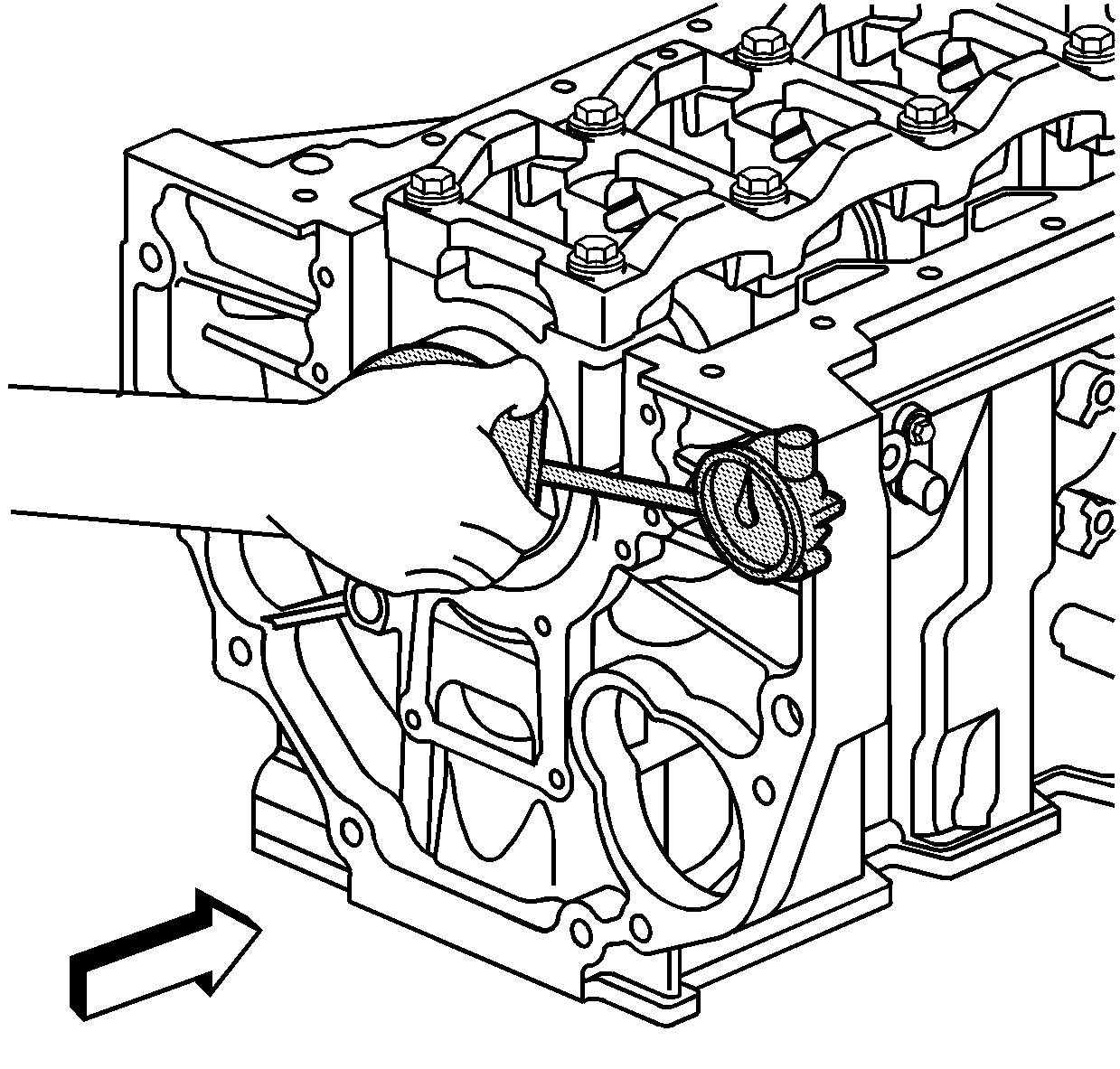
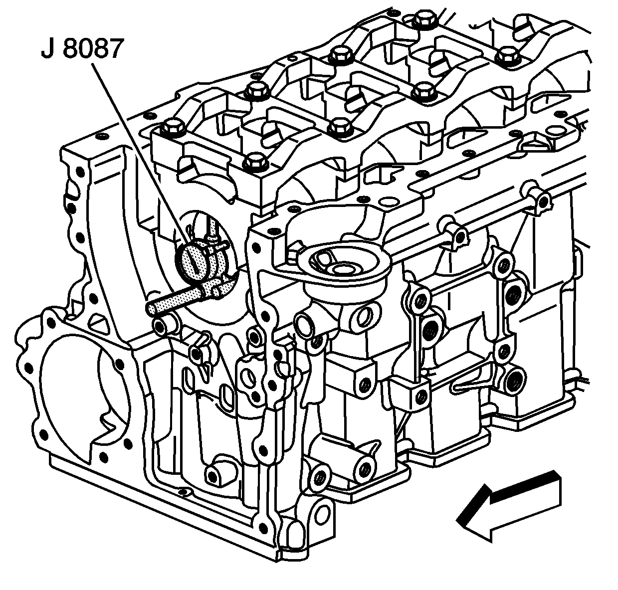
- Inspect the crankshaft main bearing bores. Use J 8087 gage to measure the bearing bore concentricity and alignment.
- Remove the crankshaft main bearing cap stiffener and main bearing caps with bearings.


| • | Wear |
| • | Taper |
| • | Runout |
| • | Ridging |

| 13.1. | Temporarily install the crankshaft. Measure the crankshaft flange runout. |
| 13.2. | Hold a gauge plate flat against the crankshaft flange. |
| 13.3. | Place J 8001 indicator set (dial indicator stem) on the transmission mounting bolt hole boss. Set the indicator to zero. |
| 13.4. | Record the readings obtained from all of the bolt hole bosses. The measurements should not vary more than 0.25 mm (0.010 in). |
| 13.5. | Recheck the crankshaft flange runout if the readings vary more than 0.25 mm (0.010 in). If the crankshaft flange runout is within the specification, replace the engine block. |

Caution: Refer to Fastener Caution in the Preface section.
| 15.1. | Tighten the crankshaft bearing cap bolts to 25 N·m (18 lb ft). |
| 15.2. | Use J 45059 meter to tighten the crankshaft bearing cap bolts an additional 180 degrees. |
Note: Perform the following inspections, and reconditioning (if necessary), with the crankshaft main bearing caps installed and tightened to specification.
