For 1990-2009 cars only
Removal Procedure
- Remove the left side insulator panel. Refer to Upper Trim Pad, Outer Trim Cover, Fuse Block Access Cover Replacement - Instrument Panel in Instrument Panel, Gages, and Console.
- Remove the knee bolster. Refer to Knee Bolster, Insulator, Molding Replacement - Instrument Panel in Instrument Panel, Gages, and Console.
- Disable the SIR system. Refer to SIR Disabling and Enabling in SIR.
- Disconnect the electrical connector from the stop lamp switch.
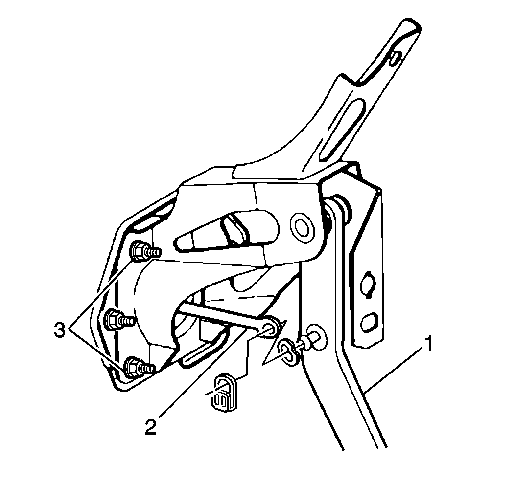
- Remove the booster push rod retain clip and washer (2) from the brake pedal assembly.
- Remove the accelerator pedal. Refer to Accelerator Pedal Replacement .
- Remove the booster push rod (2) from the brake pedal (1).
- Remove the brake booster mounting nuts (3).
- Remove the digital radio receiver and bracket if equipped. Refer to Digital Radio Receiver Replacement in Entertainment.
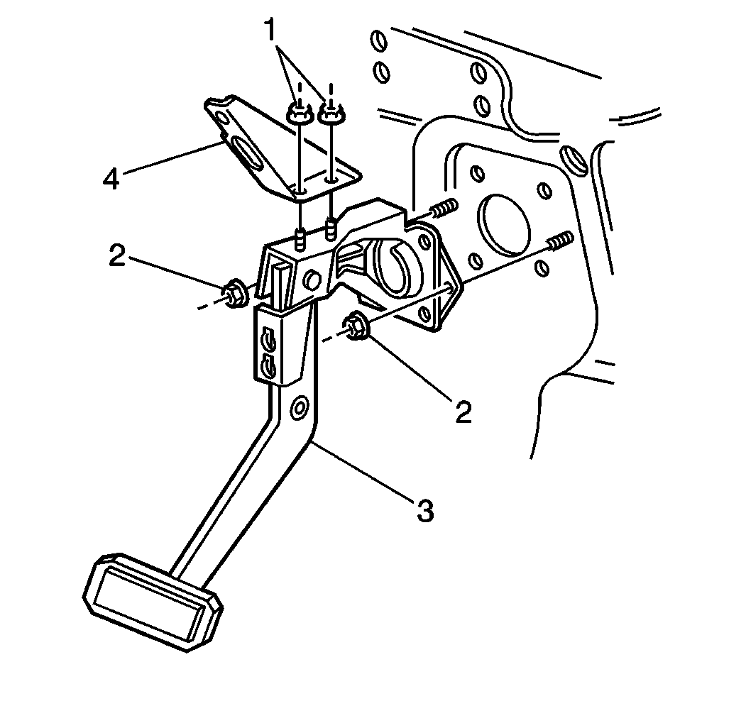
- Remove the brake pedal brace (4) mounting nuts (1).
- Remove the brake pedal brace (4) mounting bolt.
- Remove the brake pedal assembly mounting nuts (2).
- Pull master cylinder and brake booster assembly forward for additional clearance while removing brake pedal assembly.
- Remove the brake pedal assembly with the bracket (4).
- Remove the brake pedal assembly (3) from the vehicle.
- Remove the brake pedal position sensor from the brake pedal assembly . Refer to Brake Pedal Position Sensor Replacement in Lighting Systems.


Installation Procedure
- Install the brake pedal position sensor to the brake pedal assembly. Refer to Brake Pedal Position Sensor Replacement in Lighting Systems.
- Position the brake pedal brace (4) to the brake pedal assembly and install the brace mounting nuts (1).
- Install the brake pedal assembly (3) with the brace to the vehicle.
- Push the master cylinder and brake booster assembly back into position.
- Install the brake pedal brace (4) upper mounting bolt.
- Install the brake pedal assembly mounting nuts (2).
- Install the digital radio receiver and bracket if equipped. Refer to Digital Radio Receiver Replacement in Entertainment.
- Install the brake booster mounting nuts (3).
- Install the booster push rod (2) to the brake pedal (1).
- Install washer and retain clip.
- Install the accelerator pedal. Refer to Accelerator Pedal Replacement .
- Enable the SIR system. Refer to SIR Disabling and Enabling in SIR.
- Connect the electrical connector to the stop lamp switch.
- Calibrate the brake pedal position sensor. Refer to Brake Pedal Position Sensor Calibration in Lighting Systems.
- Install the knee bolster. Refer to Knee Bolster, Insulator, Molding Replacement - Instrument Panel in Instrument Panel, Gages, and Console.
- Install the left side insulator panel. Refer to Upper Trim Pad, Outer Trim Cover, Fuse Block Access Cover Replacement - Instrument Panel in Instrument Panel, Gages, and Console.
Notice: Refer to Fastener Notice in the Preface section.

Tighten
Tighten the nuts to 10 N·m (89 lb in).
Tighten
Tighten the bolt to 10 N·m (89 lb in).
Tighten
Tighten the nuts (2) to 25 N·m (18 lb ft).

Tighten
Tighten the nuts (3) to 25 N·m (18 lb ft).
