Tools Required
| • | J 35451
Reverse Light
Switch Socket |
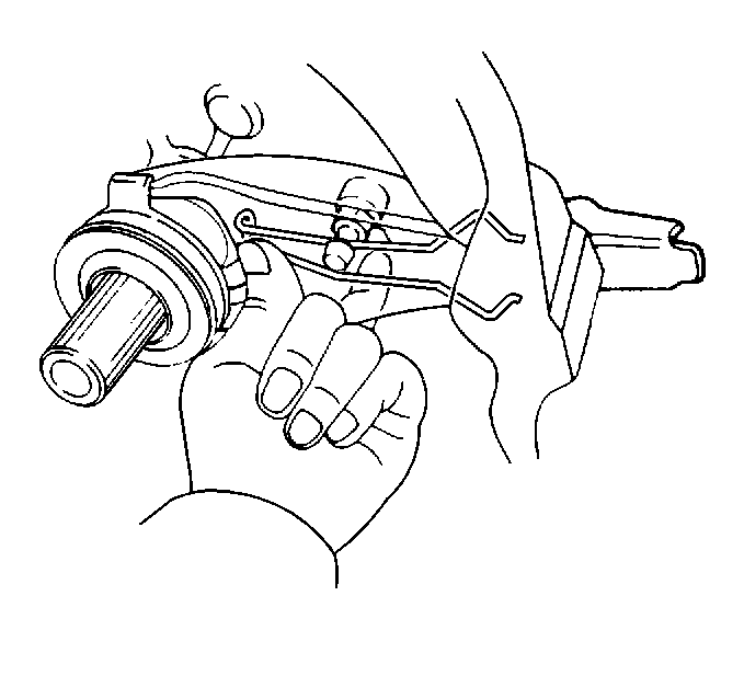
- Remove the clutch release fork and the
clutch release bearing.
- Remove one retaining bolt and remove the vehicle speed sensor (VSS)
from the transaxle case.
- Use the
J 35451
to
remove the backup switch.
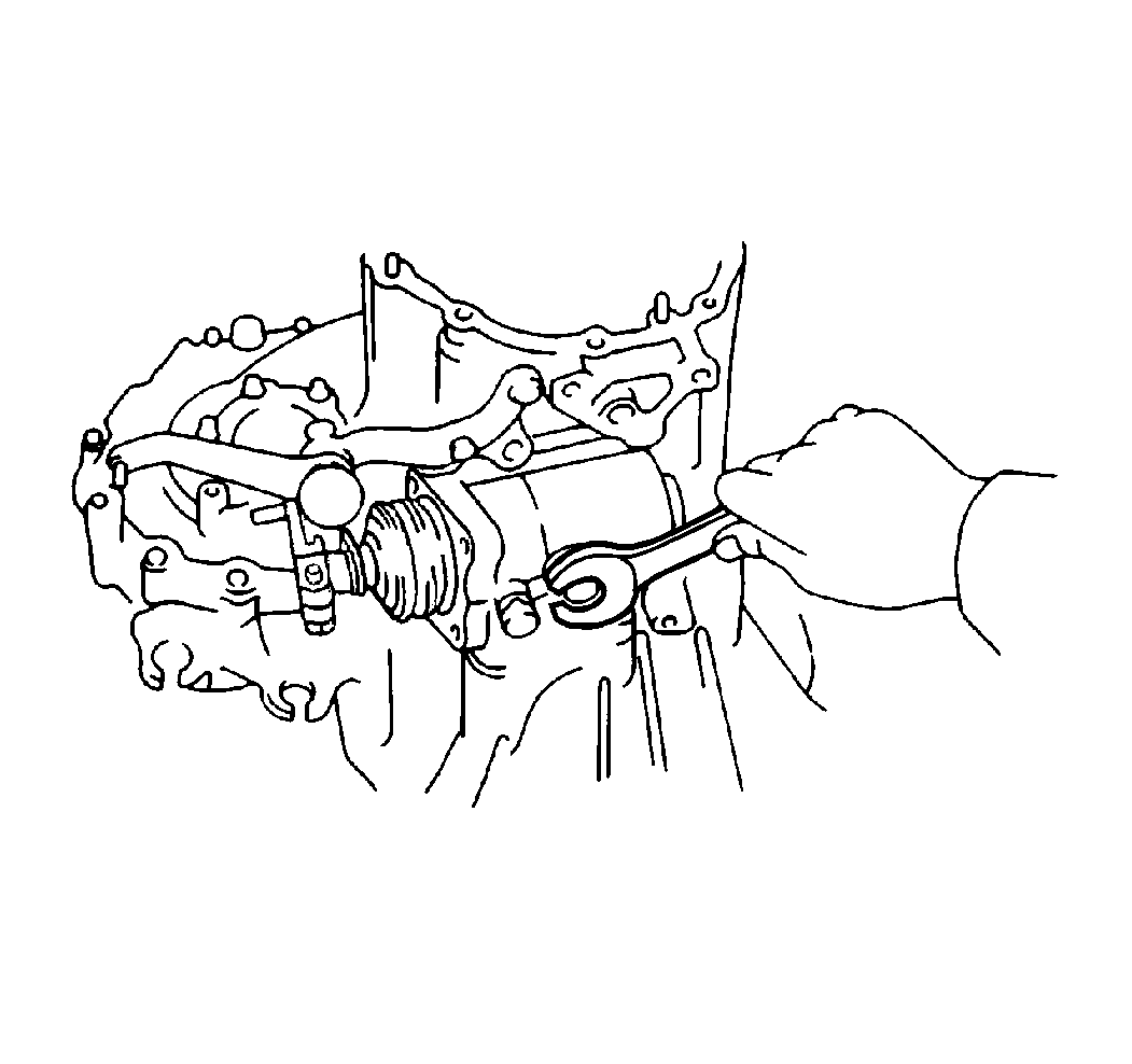
- Remove the selecting bellcrank.
- Remove the lock bolt.
- Remove the shift and select lever assembly.
- Remove the engage gears.
- Remove the fifth gear lock nut.
- Remove the disengage gears.
- Remove the case side cover bolts.
- Remove the case side cover.
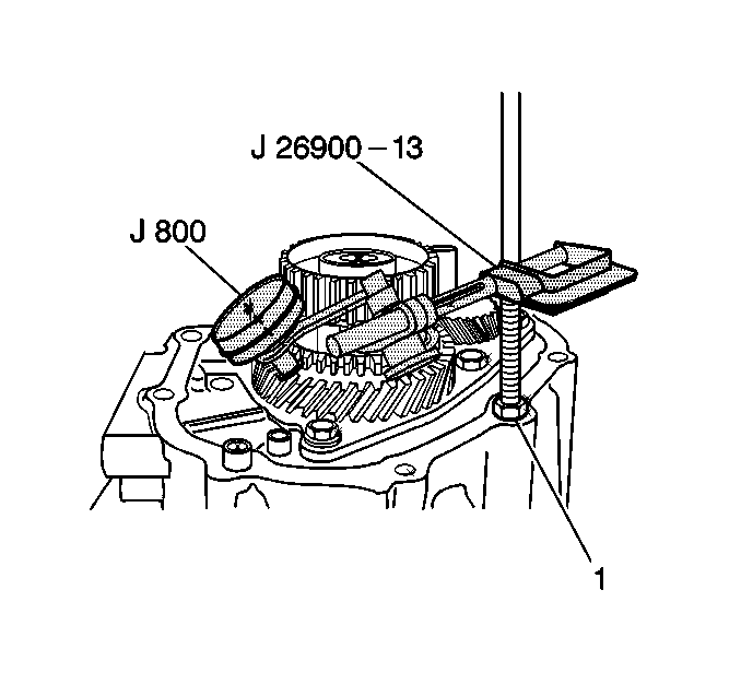
- Use the
J 8001
with the
J 26900-13
to measure the fifth gear thrust clearance. If the clearance is not 0.10-0.65 mm
(0.0039-0.0256 in), you must use a selective snap ring on reassembly.
Refer to
Transmission Specifications
#1.
- Remove the fifth gear shift fork lock bolt.
- Remove the fifth gear shift fork and synchronizer shift sleeve.
- Remove the fifth gear synchronizer snap ring.
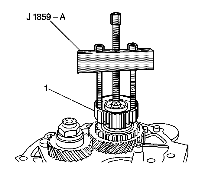
- Attach the
J 1859-A
to the
fifth gear synchronizer hub.
- Use the
J 1859-A
to
remove the fifth gear synchronizer hub (1) .
- Remove the following components:
| • | The synchronizer blocking ring |
| • | The needle roller bearing |
| • | The fifth gear driven gear |
- Unstake the fifth drive gear lock nut.
- Remove the fifth drive gear lock nut.
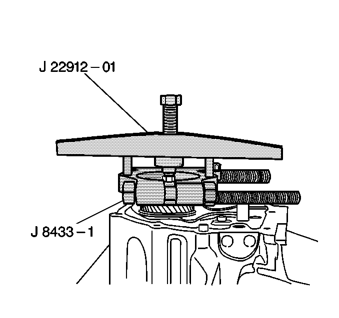
- Attach the
J 22912-B
and the
J 8433-1
to the fifth drive gear.
- Use the
J 22912-B
and the
J 8433-1
to remove the
fifth drive gear.
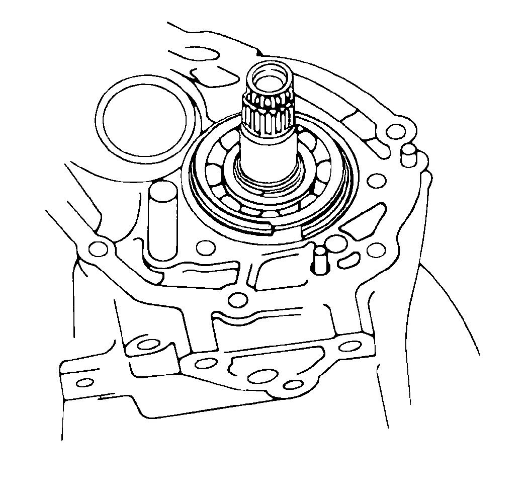
- Remove the following components:
| • | The needle roller bearing |
- Remove the rear bearing retainer.
- Remove two bearing snap rings.
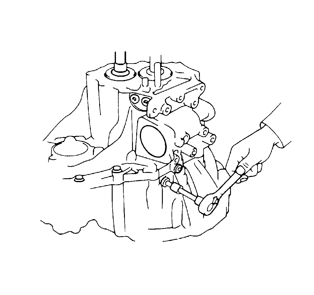
- Remove the reverse idler gear shaft lock
bolt.
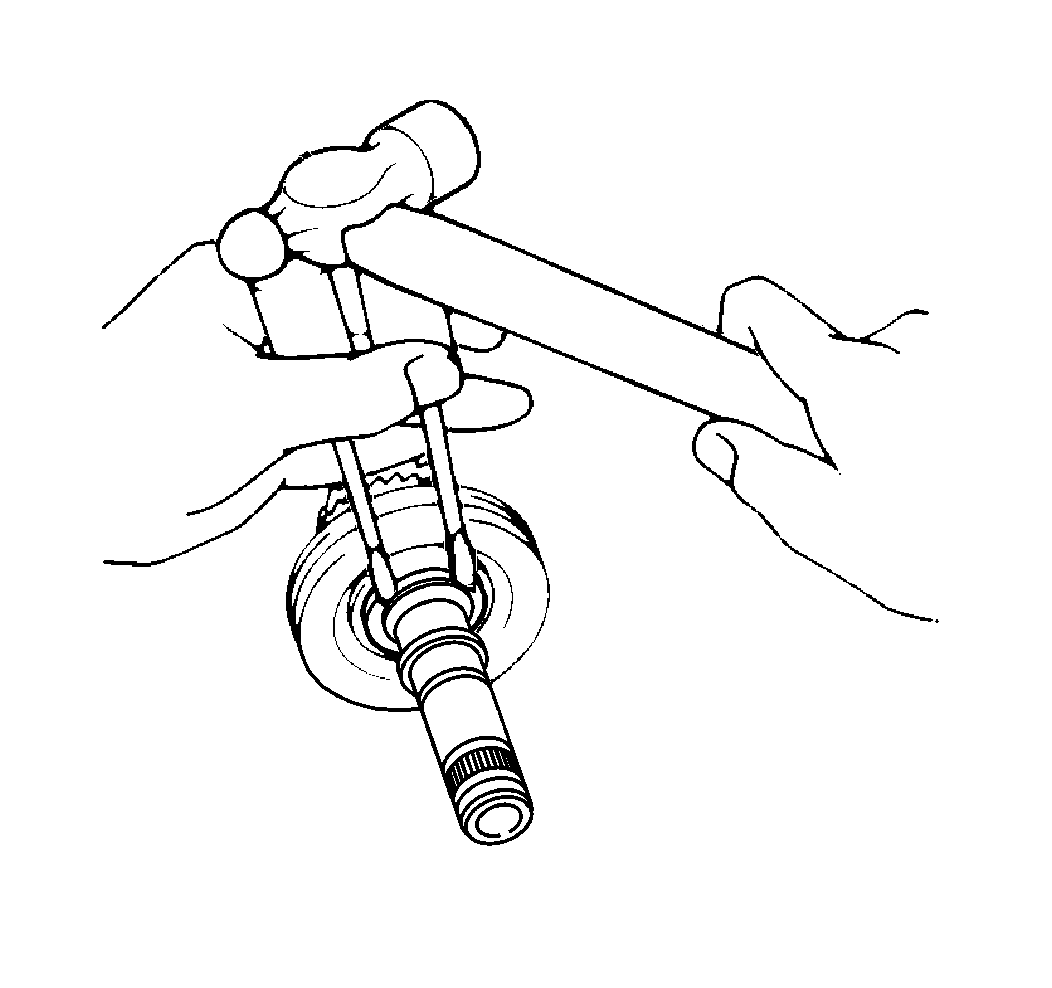
- Use two screwdrivers and a hammer to remove the snap ring from the number 2
shift fork shaft.
- Remove the following components:
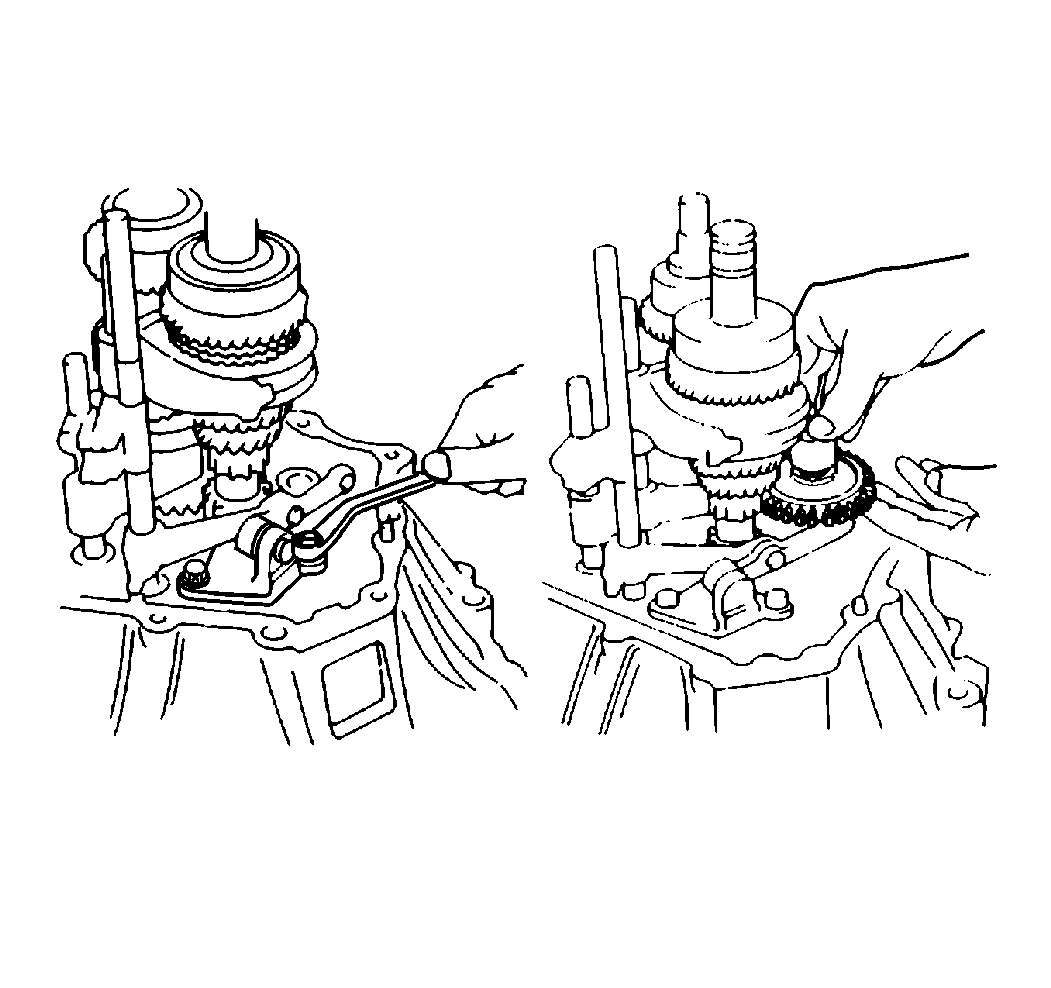
- Use a magnetic finger to remove the following
components:
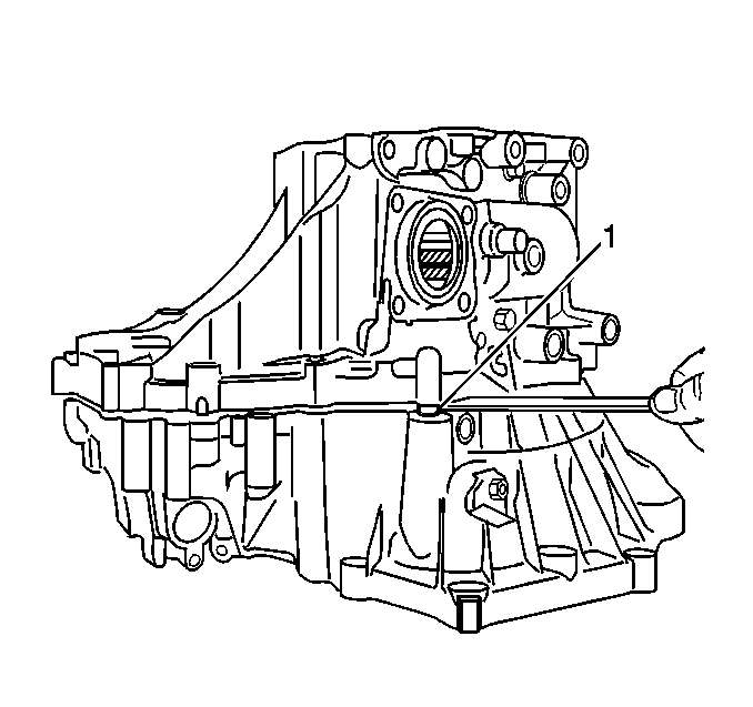
- Remove the case cover by removing 16 bolts.
- Carefully pry the case halves apart (1).
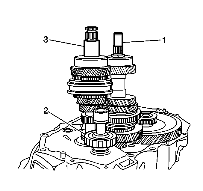
- Remove
the reverse shift arm bracket.
- Remove the following components:
| • | The reverse idler gear (2) |
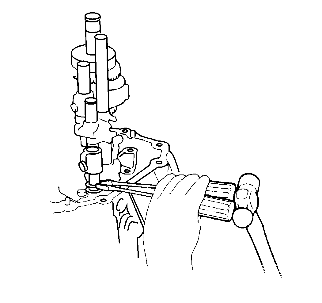
- Use two screwdrivers and a hammer to remove
three snap rings. Remove 3 set bolts from the shift forks.
- Remove the following components:
| • | The number 2 shift fork shaft |
- Use a magnetic finger to remove the two balls.
- Remove the following components:
| • | The number 3 shift fork shaft |
- Pull out the number 1 shift fork shaft.
- Remove the following components:
| • | The number 1 shift fork shaft |
| • | The number 2 shift fork shaft |
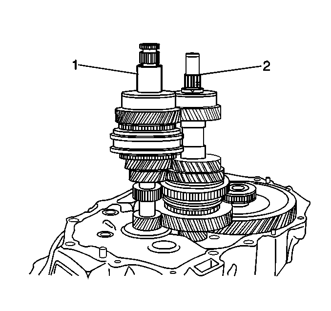
- Remove the following components together:
- Remove the differential assembly.
- Remove the following components:
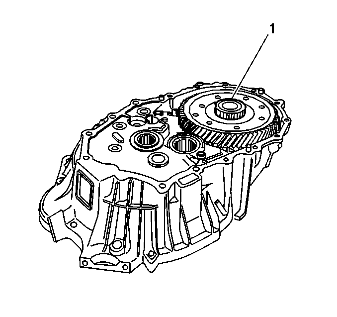
- Remove the differential assembly (1).
- Remove the following components:
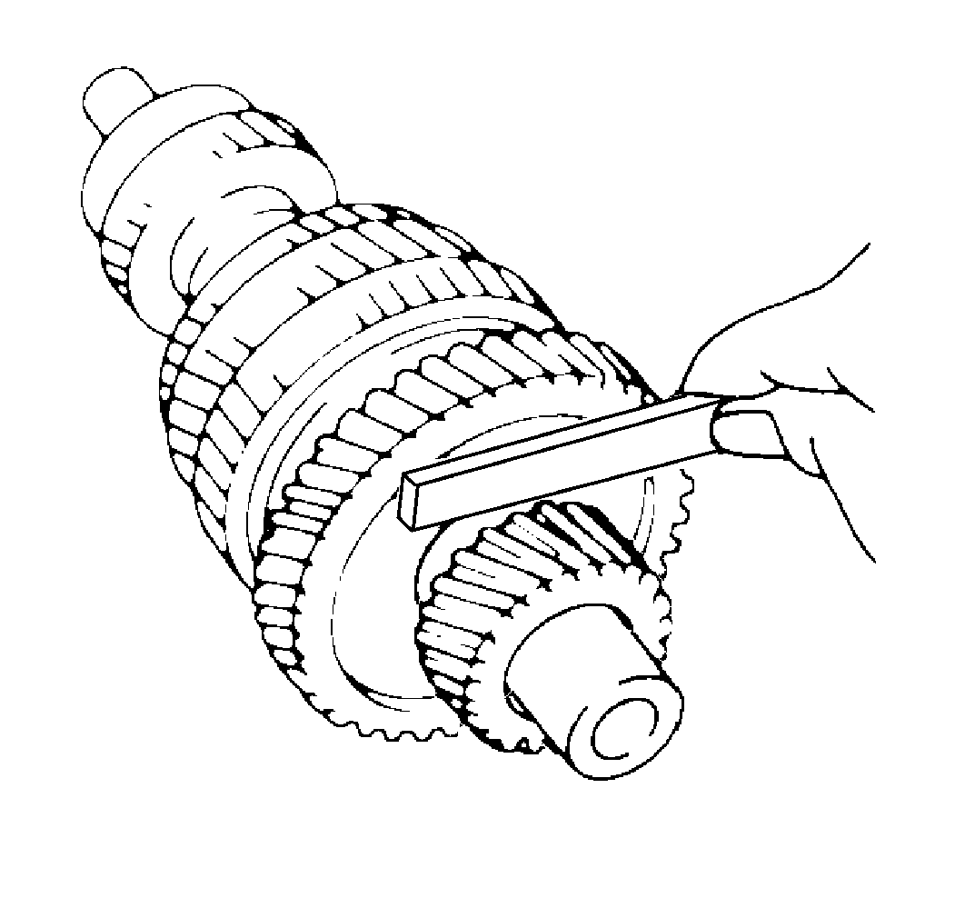
- Use a feeler gage to measure the first
gear thrust clearance. If the clearance is not 0.10-0.45 mm (0.0039-0.0177 in),
replace both of the following components:
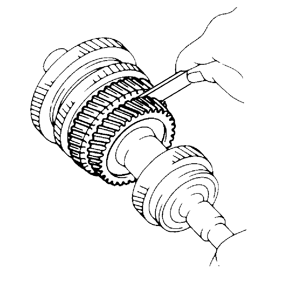
- Use a feeler gage to measure the second
gear thrust clearance. If clearance is not 0.10-0.50 mm (0.0039-0.0197 in),
replace both of the following components:
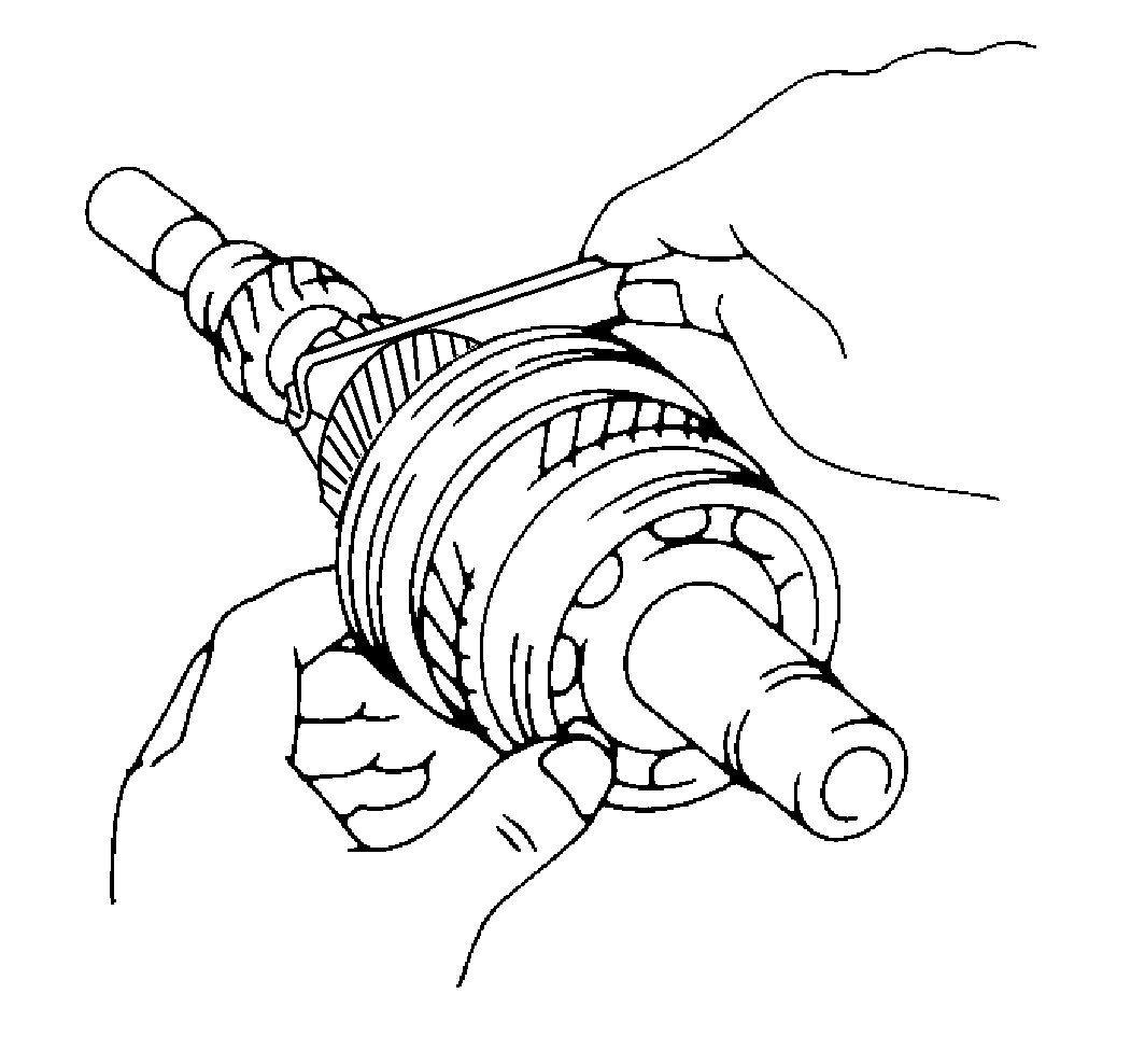
- Use a feeler gage to measure the third
gear thrust clearance. If the clearance is not 0.10 - 0.40 mm
(0.0039 - 0.0157 in), replace both of the following
components:
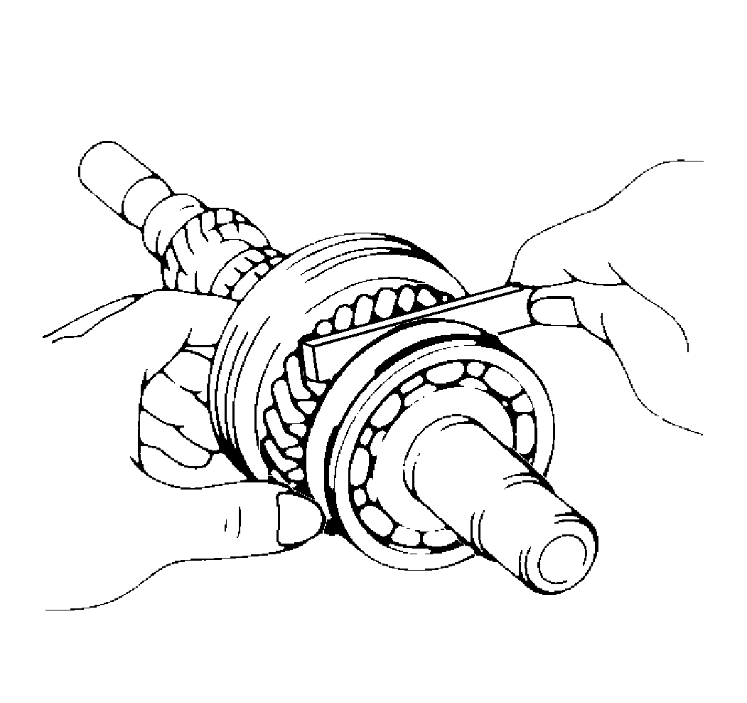
- Use a feeler gage to measure the fourth
gear thrust clearance. If the clearance is not 0.10-0.60 mm (0.0039-0.0236 in)
replace both of the following components:
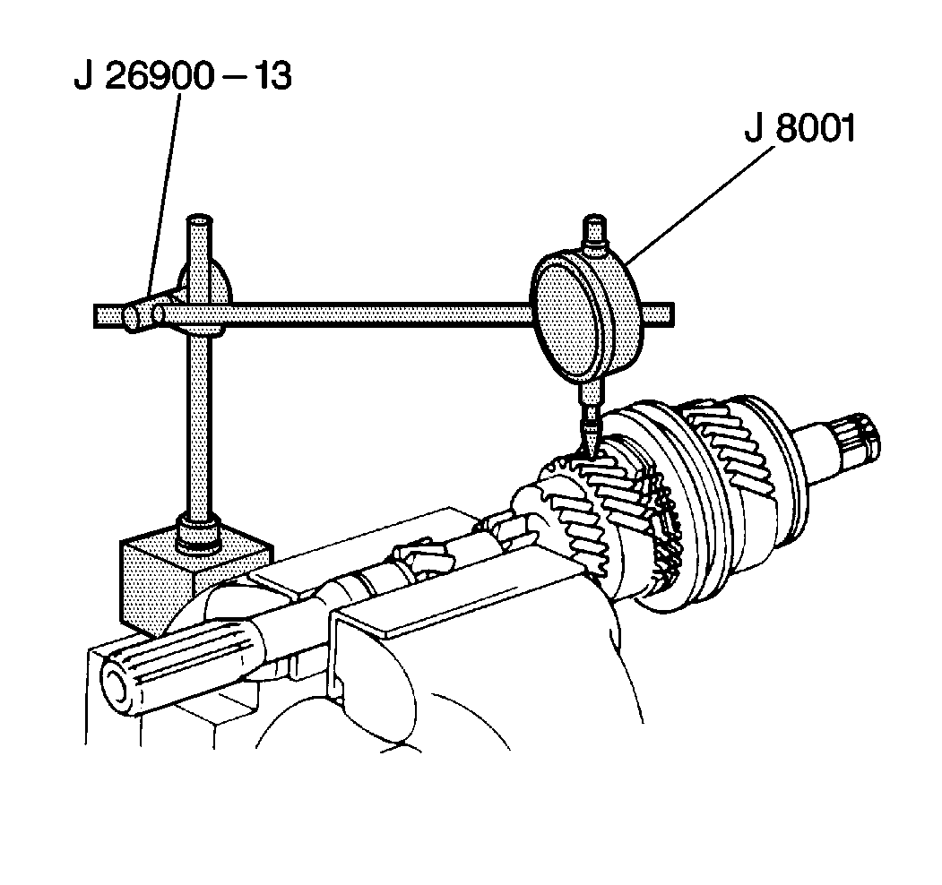
- With the needle roller bearing installed,
use a
J 8001
to measure the oil
clearance between the gear and the input shaft. If the clearance is not 0.015-0.070 mm
(0.0006-0.0028 in), replace the gear, the needle roller bearing,
or the shaft.
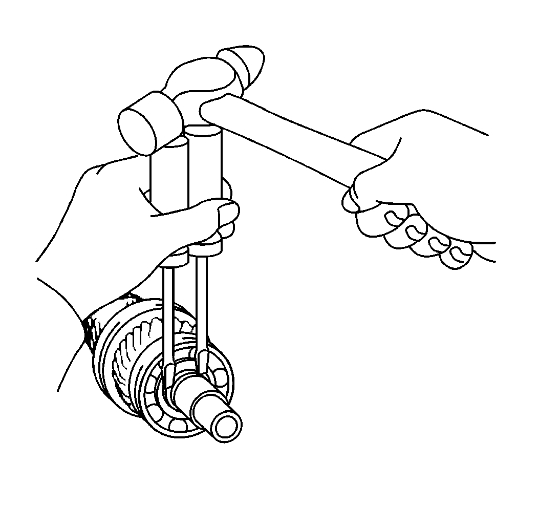
- Remove the snap ring from the input shaft.
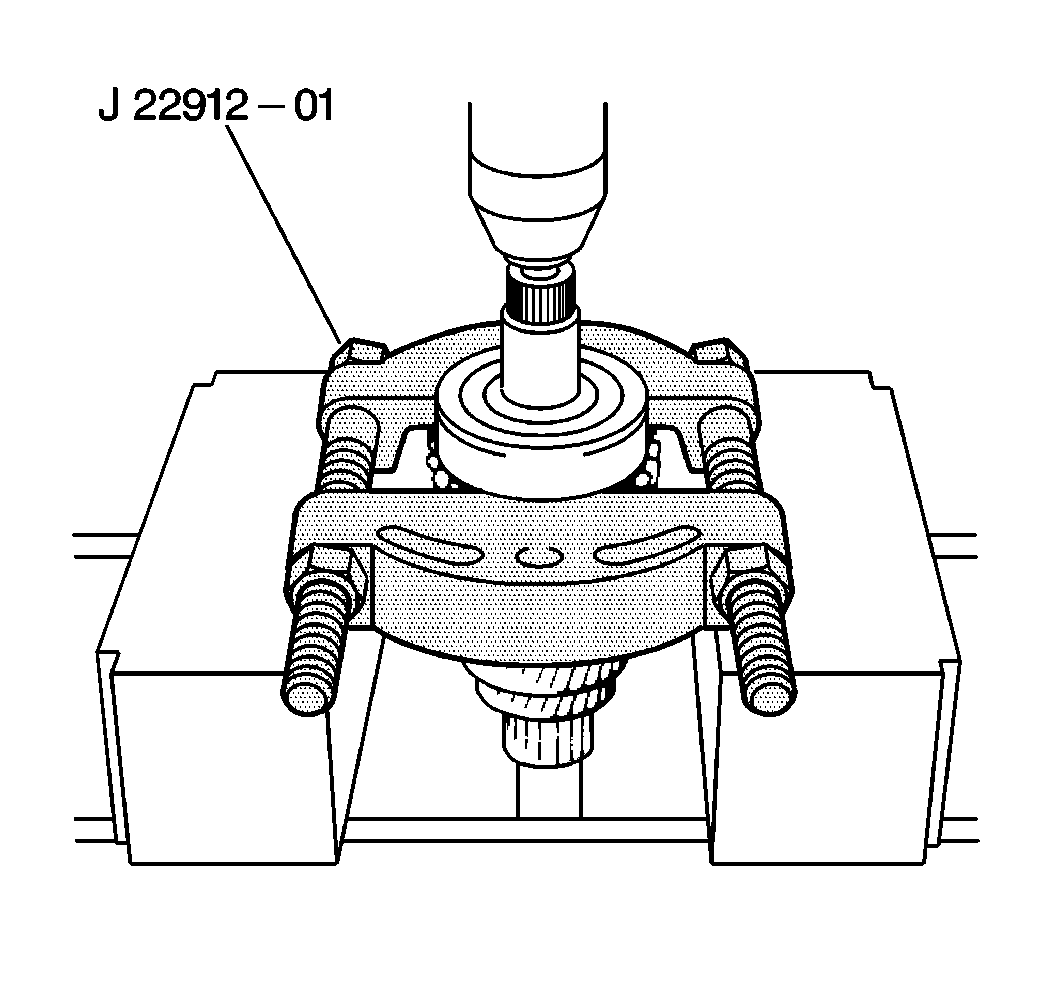
- Use a
J 22912-01
with a press to remove the radial ball bearing.
- Remove the following components:
| • | The needle roller bearing |
- Remove the snap ring from the shaft.
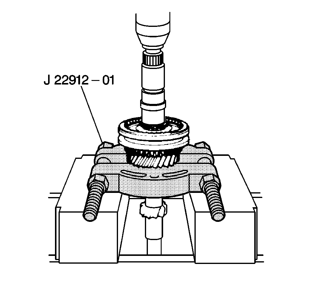
- Use a
J 22912-01
with a press to remove the following components:
| • | The number 2 hub sleeve |
| • | The third gear synchronizer ring |
| • | The needle roller bearing |
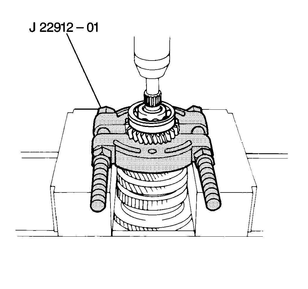
- Use a
J 22912-01
with a press to remove the following components:
| • | The radial ball bearing |
- Remove the spacer.
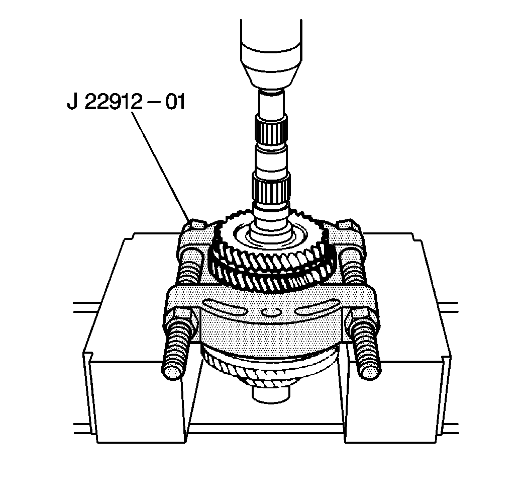
- Remove the shift number 1 hub sleeve
into the first gear.
- Use a
J 22912-01
with
a press to remove the following components:
- Remove the following components:
| • | The needle roller bearing |

- Remove the snap ring number 1 hub
sleeve assembly.
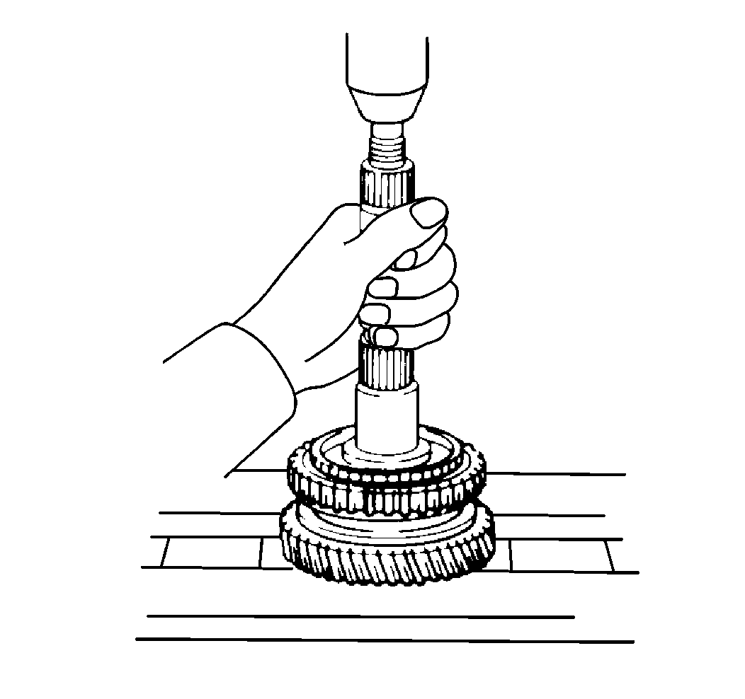
- Use a press to remove the following components:
- Remove the following components:


